Table of Contents
Advertisement
Operator's Manual
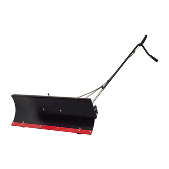
42" SNOW BLADE
Model No. 486.244411
CAUTION:
Before using this product, read
and follow all Safety, Assembly
and Operating Instructions
IMPORTANT:
For Missing Parts or
Assembly Questions Call 866-576-8388
Sears Brands Management Corporation, Hoffman Estates, IL 60179 U.S.A.
www.sears.com/craftsman
PRINTED IN U.S.A.
®
STOP
DO NOT RETURN TO STORE
For Missing Parts or Assembly
Questions Call 1-866-576-8388
•
Safety
•
Assembly
•
Operation
•
Maintenance
•
Parts
FORM NO. 41337 (03/15/10)
Advertisement
Table of Contents

Related Manuals for Craftsman 486.244411


Summary of Contents for Craftsman 486.244411
- Page 1 Operator's Manual STOP ® 42" SNOW BLADE DO NOT RETURN TO STORE For Missing Parts or Assembly Model No. 486.244411 Questions Call 1-866-576-8388 CAUTION: • Safety Before using this product, read • Assembly and follow all Safety, Assembly • Operation and Operating Instructions •...
-
Page 2: Table Of Contents
ASSEMBLY ..............5-10 REPAIR PARTS LIST..........19 OPERATION ............11-12 PARTS ORDERING/SERVICE....BACK COVER ACCESSORIES AND ATTACHMENTS These and other accessories are recommended for use with your unit. Call 1-800-4-MY-HOME® to find out if they are available. If available, they may be purchased at most Craftsman outlets or by calling 1-800-4-MY-HOME®. WEIGHT BRACKET WHEEL WEIGHT TIRE CHAINS SNOW CAB FOR DRAW BAR... -
Page 3: Full Size Hardware Chart
WARRANTY ONE YEAR FULL WARRANTY When operated and maintained according to the instructions supplied with it, if this Snow Blade fails due to a defect in material or workmanship within one year from the date of purchase, call 1-800-4-MY-HOME® to arrange for free repair (or replacement if repair proves impossible). -
Page 4: Carton Contents
PARTS IN PACKAGES NOT SHOWN FULL SIZE REF. QTY. DESCRIPTION REF. QTY. DESCRIPTION Blade Adjust Spring Cable End Fitting Plastic Grip Cable Mount Bracket Grip Assembly Angle Lock Spring Nylon Tie Angle Lock Bars Spring Mount Rod Blade Pivot Shaft Channel Pivot Pin CARTON CONTENTS (Loose Parts in Carton) REF. -
Page 5: Assembly
ASSEMBLY TOOLS REQUIRED FOR ASSEMBLY INSTRUCTIONS FOR 917 MODEL TRACTORS Pliers LOCATE MOWER SUSPENSION BRACKETS Hammer • Look under the front of your tractor. Adjustable Wrench (or socket set) • If there is a single mower deck suspension 9/16" Open End or Box End Wrench bracket located underneath the middle of the front 7/16"... - Page 6 INSTRUCTIONS FOR TRACTORS WITH DUAL STEP 2: (SEE FIGURE 2) • Fasten the R.H. Side Plate (bend facing out) to the FRONT DECK SUSPENSION BRACKETS front three holes in the tractor frame using three 3/8" x 1" carriage bolts (F), three large 1/2" washers (M) IDENTIFY YOUR SUSPENSION BRACKETS (see note) and three 3/8"...
- Page 7 INSTRUCTIONS FOR TYPE B TRACTORS STEP 2: (SEE FIGURE 2) • Attach the R.H. hanger bracket to the two front empty holes on the right side of the tractor frame using two STEP 1: (SEE FIGURE 1) new 3/8" x 1" hex bolts (D), 3/8" lock washers (R), •...
- Page 8 INSTRUCTIONS FOR ALL 917 MODEL INSTRUCTIONS FOR 247 MODEL TRACTORS TRACTORS STEP 1: (SEE FIGURE 1) STEP 1: (SEE FIGURE 1) • Assemble one slotted angle support bracket to the • Assemble one angle support bracket to the topmost top set of holes in the quick attach brackets using two set of holes in the hanger brackets using two 3/8"...
- Page 9 STEP 3: (SEE FIGURE 3) STEP 4: (SEE FIGURE 4) • Assemble a shoulder bolt (V) and a 3/8" nylock nut • Pull out on the attachment pins on the hitch assembly (L) to the front bracket on each side of the tractor, and swing the top of the pins down away from the unless a shoulder bolt is already present.
- Page 10 BLADE ASSEMBLY FOR ALL TRACTORS STEP 3: (SEE FIGURE 3) • Using a hammer, assemble a 3/8" palnut (S) onto one end of the spring mount rod. Insert the other end of STEP 1: (SEE FIGURE 1) the spring mount rod through the pivot plate using the •...
- Page 11 STEP 5: (SEE FIGURE 5) STEP 7: (SEE FIGURE 7) • Assemble one 5/16" jam nut (I) approximately 3/4" • To attach the blade to the channel assembly, align onto threaded end of control cable that has no rubber the notched holes in the pivot plate with the notched cap or preassembled nuts.
- Page 12 STEP 8: (SEE FIGURE 8) STEP 10: (SEE FIGURE 10) • Assemble the large 1/2" washer (Q) onto the channel • Remove the rubber cap and the first jam nut from the pivot pin. threaded end of the control cable and slide them onto • Attach the channel assembly to the tractor by placing the control cable wire.
- Page 13 STEP 12: (SEE FIGURE 12) • Place the end of the blade pivot rod down through the blade pivot shaft. Attach the other end of the blade pivot rod to the lift handle tube. Secure both ends with a hairpin cotter (O). The holes for the hairpin cotters should be parallel to the ground.
-
Page 14: Operation
OPERATION KNOW YOUR SNOW BLADE Read this owner's manual and safety rules before operating your snow blade. Compare the illustration below with your snow blade to familiarize yourself with the various controls and their locations. LIFT HANDLE TUBE LOCK RELEASE GRIP ASSEMBLY BLADE PIVOT ROD ANGLE LOCK... -
Page 15: Maintenance
Wheel weights and tire chains must be used with CAUTION: Carefully inspect the area your snow blade for traction. These accessories are to be worked before operating the snow available at your nearest Sears retail store. blade. Avoid pipes, roots, curbs or other heavy obstructions. -
Page 16: Service And Adjustments
SERVICE AND ADJUSTMENTS To Adjust Blade Spring To Adjust the Blade Pivot Lock Mechanism • The tension of the blade adjust spring may be altered • If the blade will not unlock and pivot, the angle lock to permit the blade to tilt forward to bypass solid bars are not disengaging from the slots in the pivot obstructions. -
Page 17: Troubleshooting
TROUBLESHOOTING PROBLEM CAUSE CORRECTION Blade is difficult to raise. Lift mechanism is binding Lubricate pivot points as shown in figure 25 on page 12. Blade is difficult to pivot. Handle tube is binding on lift rod. Lubricate lift handle rod as instructed on page 12. Blade will not unlock to pivot. Lock mechanism is out of adjustment Refer to the Service and Adjustments and is not disengaging. - Page 18 PARTS...
- Page 20 Get it fixed, at your home or ours! Your Home For expert troubleshooting and home solutions advice: www.managemyhome.com For repair – in your home – of all major brand appliances, lawn and garden equipment, or heating and cooling systems, no matter who made it, no matter who sold it! For the replacement parts, accessories and owner’s manuals that you need to do-it-yourself.
Need help?
Do you have a question about the 486.244411 and is the answer not in the manual?
Questions and answers