Table of Contents
Advertisement
Owner's Manual
CRAFTSMAN
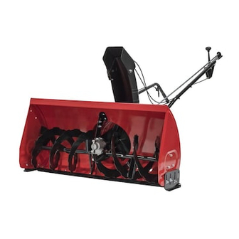
40"- 2 STAGE SNOW THROWER
TRACTOR
ATTACHMENT
Model No. 486.24839
CAUTION:
Before using this product,
read this manual and follow
all Safety Rules and
Operating
Instructions.
• Safety
• Assembly
• Operation
• Maintenance
• Parts
Sears, Roebuck and Co., Hoffman
Estates, IL 60179 U.S.A.
pRINTED
IN U.S.A.
Advertisement
Table of Contents

Subscribe to Our Youtube Channel
Related Manuals for Craftsman 486.24839


Summary of Contents for Craftsman 486.24839
- Page 1 Owner's Manual CRAFTSMAN 40"- 2 STAGE SNOW THROWER TRACTOR ATTACHMENT Model No. 486.24839 CAUTION: Before using this product, read this manual and follow all Safety Rules and Operating Instructions. Sears, Roebuck and Co., Hoffman pRINTED IN U.S.A. • Safety • Assembly •...
- Page 2 ON 40" 2-STAGE SNOWTHROWER when the unit was purchased. They are also available TIRE CHAINS MODEL NUMBER: SERIAL NUMBER: DATE OF PURCHASE: PARTS ILLUSTRATION ... BACK COVER at most Sears retail outlets DRIFT CUTTER BARS KIT NO. 71-88294 486.24839 22,2z 23,25...
- Page 3 Any power equipment can cause injury if operated the equipment. Exercise caution • Read this owner's manual carefully to operate your snow thrower and how to stop the unit and disengage the controls quickly. • Never allow children to operate the equipment. •...
- Page 4 SPARE PARTS BAG Store these two bolts and nuts In a safe place until needed. (See page 20.) REF. QTY. DESCRIPTION Hex Bolt, 1/2" x 1-1/4" Hex Bolt, 3/8" x 1" , Hex Bolt, 5/16" x 1-3/4" Hex Bolt, 1/4" x 1" Slotted Truss Head Bolt, 3/8"...
- Page 5 CARTON CONTENTS Cross Brace (Weight Tray) Side Brace (Weight Tray) Right Hand Side Plate (Stamped "R") Left Hand Side Plate (Stamped "L") Anti-rotation Bracket Engagement Rod (Not used on some models) Engine Pulley Keeper Chute Crank Rod Assembly Support Tube, Crank Rod Lift Handle Tube and Cable Cable Bracket Plastic Keg...
-
Page 6: Assembly Of Side Plates To Tractor
TOOLS REQUIRED FOR ASSEMBLY 7/16" Wrenches 1/2' Wrenches 9/16" Wrenches 3/4" Wrenches Knife ADDITIONAL ITEMS REQUIRED General Purpose Grease REMOVAL OF PARTS FROM CARTON • Remove all parts and hardware packages from the carton. Lay out parts and hardware and identify using the illustrations on pages 4 and 5. - Page 7 Assemble a shoulder bolt, a 3/8" lock washer and a 3/8" hex lock nut to the bottom hole in each side plate. See figure 3. Proceed to page 8. 3_" HEX LOCK NUT R. H. SIDE PLATE 3/8" SHOULDER BOLT FIGURE 3 TRACTORS WITH AXLE MOUNTED...
- Page 8 INSTALLING HANGER BRACKETS For better clearance, lower the tractor's suspension arms using the attachment lift lever. On Tractors With Foot Rest Brackets • Remove the bolt and nut that fasten the L.H. and R.H. foot rest brackets to the frame. See figure 7. •...
- Page 9 INSTALLING CLUTCH/IDLER This section covers the installation of the Clutch/Idler assembly to tractors with attachment clutches that are either rod operated (p, 9), cable operated (p. 10) or electric (p. 12). Use the appropriate instructions for your tractor. ROD OPERATED ATTACHMENT •...
- Page 10 Assemble the short "V" belt onto the engine pulley and then onto the large pulley on top of the clutch/ idler assembly. The belt must be placed to the inside of the engine pulley keeper, the idler pulley and the keeper bolt located beside the large pulley. See figure 14.
- Page 11 Attach the clutch/idler assembly by sliding the notched arms at the rear of the assembly onto the two shoulder to the inside of the tractor frame. Lift the front of the assembly, fitting the sides into the R.H. and L.H. hanger brackets. Attach the assembly to the brackets using two pivot lock pins and 1/8"...
- Page 12 ELECTRIC A'n'ACHMENT CLUTCHES • Turn the clutch/idler assembly upside down and place the extra tensioning chain through the left front hole as shown in figure 19. TENSIONING CHAIN FIGURE Hook the loose spring through the end of the tensioning chain. See figure 20. Hook the other end of the spring onto the bottom of the bolt and nut which secure the idler pulley to the upper idler arm.
- Page 13 Hold this drawing above you while viewing the Clutch/Idler Assembly from underneath tractor. Right and left in the drawing will be the reverse of the viewer's right and left. ENGINE PULLEY KEEPER IDLER FIGURE 22 VIEWED FROM UNDERNEATH ASSEMBLY Place the lift handle into the lift bracket on the right side of the snow thrower.
- Page 14 • Tilt the snow thrower back down to the ground. • Remove the nylon tie which fastens the auger drive belt to the discharge housing, leaving the belt assembled around the pulleys. • Remove the nylon tie which fastens the chute crank rod to the crank rod support tube.
- Page 15 A'I-rACHING SNOW THROWER TO TRACTOR NOTE: An additional person's help may be required to mount the snow thrower to the front of the tractor. • Place the tractor and snow thrower on a flat, level surface so that the tractor can be rolled forward to attach the snow blower.
- Page 16 INSTALLING THE ATTACHMENT Lift the front of the snow blower to align the holes in the mounting plates and the side plates. From the left side of the tractor install the attachment through the holes, securing it with the 1/8" hairpin cotter.
- Page 17 • Place the plastic keg on the weight tray and fill with approximately 75 Ibs. of dry sand. • Secure the keg with the rubber tarp strap hooked into the holes in the cross brace. See figure 34. TARP STRAP FIGURE USE THESE INSTRUCTIONS...
- Page 18 KNOW YOUR SNOW THROWER Read this owner's manual and safety rules before operating your snow thrower, Compare the illustration below with your snow thrower to familiarize yourself with the various controls and their locations. CHUTE TILT HANDLE Pivots the Upper Chute up or down to control the angle and distance of discharge.
- Page 19 RAISING AND LOWERING • To raise, push down on the lift handle until the snow thrower locks in the raised transport position. • To lower, push down slightly on the lift handle and pull the trigger. With the trigger pulled, slowly lower the snow thrower until it reaches the ground.
- Page 20 CAUTION: Before servicing & the snow thrower, shut off the engine, remove the spark plug wire(s), set the parking brake and remove the key from the tractor ignition. REPLACING AUGER BELT • Disengage the tractor's attachment • Lower the snow thrower to the ground. •...
- Page 21 STORAGE RECOMMENDATIONS • Lower the snow thrower to the ground. • Remove the snow thrower from the tractor. • Clean the snow thrower thoroughly. salt deposit which may have dried on the thrower and housing. • Any bare metal that has become exposed should be painted or coated with a light oil to prevent rust.
- Page 22 REPAIR PARTS FOR MODEL 486.24839 40" SNOW THROWER 23_- 27 29...
-
Page 23: Repair Parts List
Pulley, V Type 9" 43082 Nut, Hex Lock, 3/8-16 46982 Pulley, V Type 5-1/2" 738-0680 Shaft 750-0456 Spacer 750-0660 Spacer 43003 Lock Washer, 3/8" FOR MODEL 486.24839 REF. PART 714-0161 741-0919 08253B 15296A 14088B 44377 736-0247 43063 46989 47278 47044... - Page 24 REPAIR PARTS FOR MODEL 486.24839 81 62 40" SNOW THROWER...
- Page 25 Cable, Lift 712-0127 Nut, Flat Weld #10-24 710-1233 Screw, Oval #10-24 x 1" 46446 Grip, Handle 47027 Tube, Crank Rod Support 741-0475 Bushing, 3/8" Plastic FOR MODEL 486.24839 PART 703-2735A 720-0201A 44917 43850 63579 784-5604 720-0232 603-0302 731-1313B 746-0928 746-0929...
- Page 26 NOTES...
- Page 27 10 ° CAUTION: DO NOT OPERATE YOUR TRACTOR AND SNOW & THROWER ON A SLOPE IN EXCESS OF 10 DEGREES. BE SURE OF YOUR TRACTOR'S TOWING AND BRAKING CAPABILITIES BEFORE OPERATING ON A SLOPE. AVOID ANY SUDDEN TURNS OR MA- NEUVERS WHILE ON A SLOPE.
- Page 28 For in-home major brand repair service: Call 24 hours a day, 7 days a week 1-800-4-MY-HOME" 0-800-469-4663) Para pedir servicio de reparaci6n a domicilio - 1-800-676-5811 In Canada for all your service and parts needs call - 1-600-665-4455 Au Canada pour tout le service ou les pi_ces For the repair or replacement parts you need: Call 7 am - 7 pm, 7 days a week...
Need help?
Do you have a question about the 486.24839 and is the answer not in the manual?
Questions and answers
what year is this snowblower
The manual states that it was printed in the U.S.A. and includes a "LIMITED ONE YEAR WARRANTY" section, but it does not specify the exact year of manufacture for the Craftsman snowblower with part number 486.24839. Therefore, the year it was made cannot be determined from the provided information.
This answer is automatically generated