Table of Contents
Advertisement
Quick Links
Advertisement
Table of Contents

Related Manuals for Sony HDW F900R - CineAlta Camcorder - 1080p


Summary of Contents for Sony HDW F900R - CineAlta Camcorder - 1080p
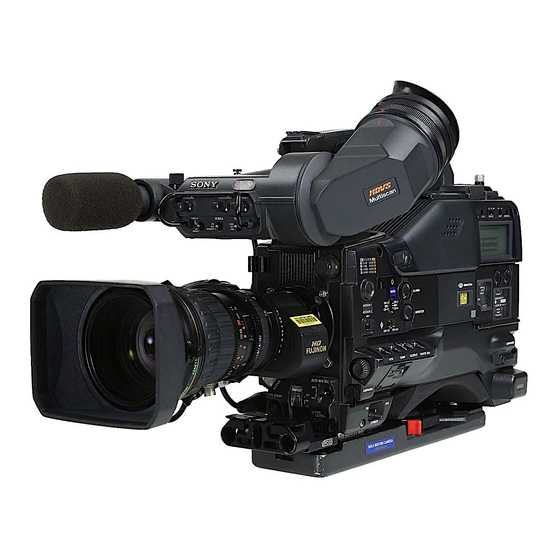
- Page 1 HD CAMCORDER HDW-F900R OPERATION MANUAL [English] 1st Edition...
- Page 2 WARNING AVERTISSEMENT To reduce the risk of fire or electric shock, Afin de réduire les risques d’incendie ou do not expose this apparatus to rain or d’électrocution, ne pas exposer cet moisture. appareil à la pluie ou à l’humidité. To avoid electrical shock, do not open the Afin d’écarter tout risque d’électrocution, cabinet.
- Page 3 WARNUNG Um die Gefahr von Bränden oder elektrischen Schlägen zu verringern, darf dieses Gerät nicht Regen oder Feuchtigkeit ausgesetzt werden. Um einen elektrischen Schlag zu vermeiden, darf das Gehäuse nicht geöffnet werden. Überlassen Sie Wartungsarbeiten stets nur qualifiziertem Fachpersonal. Für Kunden in Europa Dieses Produkt besitzt die CEKennzeichnung und erfüllt die EMVRichtlinie (89/336/EWG) der EGKommission.
-
Page 4: Table Of Contents
Table of Contents Setting the Frame Frequency ..........9 Chapter 1 Overview 1-1 Features ................. 11 1-1-1 Camera Features .............11 1-1-2 VTR Features ..............12 1-1-3 Other Features..............12 1-2 Example of System Configuration ......14 1-3 Precautions ..............15 1-4 Using the CD-ROM Manual .......... 15 1-4-1 Preparations ..............15 1-4-2 Reading the CD-ROM Manual ........15 Chapter 2 Locations and Functions of Parts and Controls... - Page 5 3-2-6 Shooting Picture at Intervals (Interval Rec Function: with the HKDW-703)..............43 3-2-7 Continuous Recording on Previous Cut......50 3-2-8 Searching for the Last Recorded Portion and Turning on Recording Pause Mode (End Search Function) ....51 3-3 Checking Recording and Playback......51 3-3-1 Checking the Last Two Seconds of the Recording — Recording Review............51 3-3-2 Checking the Recording on the Color Video Monitor —...
- Page 6 4-5-3 Setting the User Bits ............73 4-5-4 Synchronizing the Time Code ........73 Chapter 5 Menu Displays and Detailed Settings 5-1 Menu Organization and Operation ......75 5-1-1 Menu Organization ............75 5-1-2 Basic Menu Operations...........76 5-1-3 Editing the USER Menu ..........78 5-1-4 Adding Functions to be Assigned to Assignable Switches.
- Page 7 Chapter 6 Saving and Loading User Setting Data 6-1 Saving and Loading User Files ........106 6-1-1 Handling the “Memory Stick” ........106 6-1-2 Saving USER Menu Data (User File) to the “Memory Stick”................107 6-1-3 Loading Saved Data from a “Memory Stick” ....109 6-2 Saving and Loading Scene Files........110 6-2-1 Saving a Scene File ............110 6-2-2 Loading a Scene File.............112...
- Page 8 Chapter 8 Maintenance 8-1 Testing the Camcorder Before Shooting ....130 8-1-1 Preparations for Testing..........130 8-1-2 Testing the Camera ............130 8-1-3 Testing the VTR............132 8-2 Maintenance ..............134 8-2-1 Cleaning the Video Heads ..........134 8-2-2 Cleaning the Viewfinder ..........134 8-3 Operation Warnings............ 135 Appendixes Specifications..............
-
Page 9: Setting The Frame Frequency
Or, if you have used the MAINTENANCE menu Setting the Frame before, the page that was on the screen when the last menu operation ended appears. Frequency When the CONTENTS page is displayed, push the MENU knob once, and then turn the MENU knob to move the mark to FORMAT. - Page 10 The frame frequency selected on the NEXT line is displayed on a colored background. The setting changes in the order of 59.94 y 50i y 23.98 y 24PsF y 25PsF y 29.97 … The frame frequency selected on the NEXT line is displayed on a colored background.
-
Page 11: Chapter 1 Overview
The camcorder is compatible with multiple formats such as 23.98PsF, 24PsF, 25PsF, 29.97PsF, 59.94i, and 50i. 1) “Memory Stick” is a registered trademark of Sony Corporation. (However, the camcorder is not compatible with the 60i and 30P formats.) Saving and recalling settings from a 1) Abbreviation of “Power Hole-Accumulated Diode.”... -
Page 12: Vtr Features
camera image and playback image in 1080/23.98PsF and to hold the time code for approximately 5 years without 1080/59.94i format on an NTSC monitor. supplying the power to the camcorder. • These optional boards make it possible to output an SDI •... - Page 13 Audio functions • The MIC IN (microphone input) connector (XLR type, 5-pin, female) allows you to connect the supplied stereo microphone. You can record either stereo or monaural sound. • An optional slot-in UHF portable tuner, WRR-855A/ 855B, can be attached. •...
-
Page 14: Example Of System Configuration
1-2 Example of System Configuration The diagram below shows a typical configuration of the For more information about the fittings, connections, or camcorder for ENG and EFP. use of additional equipment and accessories, see “Chapter In this manual, an optional HDVF-20A HD Electronic 7 Setting Up the Camcorder”... -
Page 15: Precautions
4-1 Preparations” above. Notes • If you have lost or damaged the CD-ROM, you can purchase a new one to replace it. Contact your Sony service representative. • You can purchase a printed version of the operation manual (English version). Contact your Sony service representative. - Page 16 When ordering, be sure to specify the part number of the manual you want. Part No. Models covered 3-991-858-0X HDW-F900R Using the CD-ROM Manual...
-
Page 17: Chapter 2 Locations And Functions Of Parts And Controls
Locations and Functions of Parts and Controls Chapter 2-1 Power Supply a Battery attachment b DC IN connector c POWER switch d LIGHT switch a Battery attachment AUTO: When the switch on the video light is in the on Attach a battery pack, BP-GL65, BP-GL95, or BP-L60S. position, putting the camcorder in recording mode Alternatively, by attaching an AC-DN10 AC Adaptor, you turns the video light on automatically. -
Page 18: Accessory Attachments
Remove this cap by pushing up the lens mounting lever. When no lens is mounted, keep this cap fitted for protection from dust. g LENS connector (12-pin) Fit the lens cable to this connector. Contact your Sony representative for more information about the lenses you can use. Accessory Attachments... -
Page 19: Audio Functions
2-3 Audio Functions h Built-in speaker a Microphone d EARPHONE jack (rear) b MIC IN connector g ALARM volume control f MONITOR volume control c MIC LEVEL control e MONITOR switch and CH-1/2 / CH-3/4 switch d EARPHONE jack (front) Audio functions (1) a Microphone You can connect earphones to both connectors at the same... - Page 20 g ALARM volume control CH-1/2 / MONITOR Audio output Adjusts the speaker or earphone alarm volume. At the CH-3/4 switch switch minimum position, no sound can be heard. position position CH-1/2 CH-1 Audio channel 1 Mix sound of channels 1 and 2 CH-2 Audio channel 2 CH-3/4...
- Page 21 k AUDIO IN CH-1/CH-2 / CH-3/CH-4 (audio input n +48V/OFF switches selection) switches Select either of the following positions for the microphones to be connected. CH-1/CH-2 switches +48V: For a microphone to use an external power supply Select the audio input signals to be recorded on audio OFF: For a microphone to use an internal power supply channels 1 and 2.
-
Page 22: Shooting And Recording/Playback Functions
2-4 Shooting and Recording/Playback Functions a Viewfinder h Diopter adjustment ring Eyecup b TALLY indicator c BRIGHT control d CONTRAST control e PEAKING control f ZEBRA switch g TALLY switch j Viewfinder left-right positioning ring k Camera operator tally indicator i Viewfinder front-rear l Viewfinder stopper positioning lever... - Page 23 i Viewfinder front-rear positioning lever For information about how to change the zebra pattern setting in the setup menu, see “5-2-6 Setting the To adjust the viewfinder position in the front-rear Viewfinder” on page 88. direction, loosen this lever and the LOCK knob. After adjustment, retighten this lever and the LOCK knob.
-
Page 24: Gain Selector
For details about setting the gain values, see “5-3-1 FILTER selector (inner knob) setting ND filter selection Setting Gain Values for the GAIN Selector Positions” on /16 ND page 93. /64 ND s OUTPUT/DCC (output signal/dynamic contrast Examples of shooting conditions and appropriate filters control) switch Switches the video signal that is output to the VTR, Shooting condition... - Page 25 u TURBO GAIN button B (ATW): When this switch is set to B and on the When shooting under extremely poor lighting conditions, FUNCTION 2 page of the OPERATION menu, press the button once to boost the video gain to the value WHITE SWITCH<B>...
- Page 26 z VTR START button wj VTR SAVE/STBY switch wk EJECT button wl REW button and indicator e; F FWD button and indicator ea PLAY button and indicator es STOP button Shooting and recording/playback functions (4) z VTR START button MODE page of the MAINTENANCE menu. The STBY Press this button to start recording.
-
Page 27: Menu Operating Section
2-5 Menu Operating Section a “Memory Stick” compartment c STATUS ON/SEL / OFF switch d MENU ON/OFF switch e CANCEL/PRST / ESCAPE switch Switch cover b MENU knob a “Memory Stick” compartment b MENU knob Changes the page selection or a setting within the menu. Push: If you push this knob when the arrow ( ) is placed at the page title on the menu, the arrow changes to a... - Page 28 Closing the cover automatically sets this switch to OFF. ON: Displays the menu on the viewfinder screen or the test signal screen, at the last accessed page. When the menu is used for the first time, the first page is displayed. OFF: Removes the menu from the viewfinder screen or the test signal screen.
-
Page 29: Time Code System
2-6 Time Code System a GENLOCK IN connector b TC IN connector c TC OUT connector Time code functions (1) a GENLOCK IN connector (BNC type) • This connector inputs an HD reference signal when the camera is to be genlocked or when the time code is to be synchronized with external equipment. - Page 30 d HOLD button e RESET button f DISPLAY switch g ADVANCE button h SHIFT button i PRESET/REGEN/CLOCK switch j F-RUN/SET/R-RUN switch k DATA DISPLAY switch Time code functions (2) d HOLD (display hold) button PRESET: Records time code with a preset initial value. Pressing this button instantly freezes the time data REGEN: Records time code continuous with the existing displayed in the counter display section.
-
Page 31: Warnings And Indications
2-7 Warnings and Indications Besides the viewfinder, speaker and earphones, the indicators and displays described in this section also provide you with information such as the operating state of the camcorder and warnings. a TALLY indicator b DISPLAY/ASPECT switch c TALLY switch d BACK TALLY indicator e BACK TALLY switch f LCD LIGHT switch... -
Page 32: Warnings And Indications On The Display Panel
OFF: The BACK TALLY and REAR TALLY indicators 2-8 Warnings and are disabled. f LCD LIGHT switch Indications on the Display Turns on/off the display panel light. Panel g WARNING indicator Lights up or flashes when there is a fault in the VTR. For details, see “8-3 Operation Warnings”... -
Page 33: Time Code Display
VTR operation status and status indicators Switch settings related to time code and displayed information DISPLAY DATA DISPLAY Displayed information switch position switch position Lights during playback Any position Control signal Any position Time code DATA U-BIT User bits SHOT TIME Data and time from shot data SHOT-NO... -
Page 34: Indicators In The Viewfinder
To prevent interruption during operation, replace the 2-9 Indicators in the battery as soon as this indicator starts flashing. The level at which the indicator starts flashing can be set Viewfinder on the BATTERY page (page 153) of the MAINTENANCE menu. (warning) indicator Several indicators are provided above and below the Lights up when the camcorder is used under one or more... -
Page 35: Chapter 3 Recording And Playback
Recording and Playback Chapter 3-1 About Cassettes EJECT button This section describes the procedure for loading and unloading a cassette. See Specifications “VTR Section” on page 138 for information about the cassettes you can use in the Cassette camcorder. compartment lid 3-1-1 Loading and Unloading a Check that there is no slack in the tape. -
Page 36: Preventing Accidental Erasure
3-1-2 Preventing Accidental Erasure The following procedure prevents cassettes from being recorded inadvertently. Push the plug in. To reuse the cassette, return the plug to its original position. Unloading a cassette With the power supply on, press the EJECT button to open the cassette compartment lid. -
Page 37: Recording
From adjusting the black balance and 3-2 Recording white balance to stopping recording After turning on the power and loading a cassette, set the switches and selectors as shown below and begin operation. 3-2-1 Basic Procedures This section describes the basic procedures for shooting AUDIO SELECT DISPLAY: ON CH-1/CH-2: AUTO... -
Page 38: Continuous Recording
When the camcorder is in Recording B: 3200K C: 4300K Pause mode D: 6300K Pressing the VTR START button on the camcorder or the VTR button on the lens continues recording at exactly the For details, see “4-1-2 Adjusting the White Balance” next frame. -
Page 39: Recording Good Shot Marks
Setting for recording good shot marks on For details, see “3-2-8 Searching for the Last Recorded Portion and Turning on Recording Pause Mode (End the LTC-UBIT area on the tape Search Function)” on page 51. Looking in the viewfinder, press the PLAY button to Switch cover start playback. -
Page 40: Recording A Recording Start Mark
When any page of the MAINTENANCE menu is Set the mark(s) to be recorded to ON. displayed, turn the MENU knob until the SHOT 1 Turn the MENU knob to move the mark to the MARKER page appears. mark to be set, then push the MENU knob. Push the MENU knob. -
Page 41: Starting A Shoot With A Few Seconds Of Pre-Stored Picture Data (Picture Cache Function: With The Hkdw-703)
For detailed information on setting whether or not Picture Cache Recording start point recording start markers are recorded, see “Setting for time VTR STBY mode VTR SAVE mode recording good shot marks on the LTC-UBIT area on the 2 (seconds) About 2 seconds About 2 seconds tape”... - Page 42 mark appears on the left of the currently selected Turn the MENU knob to move the mark to CACHE item and a z mark appears on the left of the setting. REC TIME. Turn the MENU knob to move the mark to CACHE/ INTVAL REC.
-
Page 43: Shooting Picture At Intervals (Interval Rec Function: With The Hkdw-703)
Camcorder operations in Picture Cache mode picture data, equal to that recorded during the Picture Cache time, will be lost, because it has not yet been The recording procedure in Picture Cache time is basically recorded on the tape. the same as that for normal recording. However, note the following differences. - Page 44 Turn the MENU knob until A. INT appears. To turn on Auto Interval Rec mode, proceed as follows. As you turn the MENU knob, the setting changes in the following sequence: OFF y CACHE y A. INT y M. INT. When A.
- Page 45 Turn the MENU knob to move the mark to REC mark on the left of PRE-LIGHTING changes to TIME. a z mark and the z mark on the left of the setting changes to a ? mark. Turn the MENU knob until the desired time to turn on the light before starting to record appears.
- Page 46 Basic Procedures” (page 37), secure the camcorder so that it will not move. Total time for shooting (TAKE TOTAL TIME) Press the VTR START button on the camcorder or the Shooting interval VTR button on the lens. The camcorder starts recording in Auto Interval Rec mode.
- Page 47 Manual Interval Rec mode mark on the left of NUMBER OF FRAME changes to a z mark, and the z mark on the left of the Manual Interval Rec has the following two modes. setting changes to a ? mark. Single Trigger mode: Each time the VTR START button or VTR button on the lens is pressed, the camcorder Turn the MENU knob until the desired number of...
- Page 48 The menu display disappears from the viewfinder • Set the POWER switch to OFF. screen and the message MANU INTERVAL *FRAME, indicating the single trigger mode of the Setting Continuous Trigger mode of Manual Interval Rec mode, appears along the bottom Manual Interval Rec of the viewfinder.
- Page 49 Recording in Continuous Trigger mode of Turn the MENU knob clockwise or counterclockwise until the desired time interval at which to turn on the Manual Interval Rec light before recording starts appears. Note If you turn the MENU knob clockwise or When you use blank cassettes, such as brand new cassettes, counterclockwise, the PRE-LIGHTING time changes be sure to record color bars for more than 2 seconds at the...
-
Page 50: Continuous Recording On Previous Cut
Cassette control buttons For detailed information, see “5-3-5 Assigning Functions to Assignable Switches” on page 96. While recording in Single Trigger mode of Manual Interval Rec (the green TALLY indicator in the viewfinder flashes (2 flashes/second)), you cannot use the cassette Continuous recording the new cut after the control buttons (REW, F FWD, PLAY and STOP). -
Page 51: Recording Pause Mode (End Search Function)
3-2-8 Searching for the Last 3-3 Checking Recording Recorded Portion and Turning on and Playback Recording Pause Mode (End Search Function) By pressing the PLAY button, you can review any length The End Search function allows the camcorder to search of recording in the viewfinder in black and white. -
Page 52: Checking The Recording On The Color Video Monitor
3-3-2 Checking the Recording on HDW-F900R the Color Video Monitor — Playback NTSC/PAL monitor in Color Connect an HD color video monitor with an HD-SDI input SDI input connector or connector to the HD-SDI OUT connector of the video input camcorder. -
Page 53: Recording The Recording Start Time Code Onto The Memory Label - Tele-File
3-4 Recording the HDW-F900R HD monitor Recording Start Time HD-SDI input Code onto the Memory connector Label — Tele-File HD monitor HD-SDI OUT TEST OUT The VTR section is compatible with the Tele-File memory label system. This system allows you to record the Video input connector recording start time code, model name, serial number and tape format onto an optional MLB-1M-100 memory label. - Page 54 The following three Tele-File marks are available: Message Meaning • OK: Place this mark when you decide the recorded TELE-FILE MARK: KP States that a KP mark images are good. has been recorded. • NG: Place this mark when you decide the recorded TELE-FILE MARK: ERASE States that the Tele-File images are not good.
-
Page 55: Warning/Error Messages In Memory Label Operation
Even if you press the ASSIGN 1 switch when a Tele-File Turn the MENU knob clockwise or counterclockwise mark is not displayed, the Tele-File mark set on the menu until the desired Tele-File mark appears. will not be displayed. The Tele-File mark changes in the order of OK y NG y KP…... -
Page 56: Confirming The Remaining Capacity On The Memory Label
3-4-4 Confirming the Remaining Notes • When the memory label is protected from accidental Capacity on the Memory Label erasure, you cannot clear recorded data. • The time code data is cleared. However, the memory Follow steps 1 to 3 in “Setting the Tele-File mark to be label ID is not affected. -
Page 57: Freezing A Picture During Playback
Push the MENU knob. 3-5 Freezing a Picture The ? mark on the left of the setting returns to a z mark, and the z mark on the left of STOP KEY During Playback FREEZE returns to an mark. To end menu operation, set the MENU ON/OFF switch to OFF. -
Page 58: Setting The Stand-By Off Timer During Rec-Pause
3-6 Setting the Stand-by off Timer During Rec- Pause The VTR SAVE/STBY switch allows you to control the VTR power mode during pauses in recording (rec-pause) or when stopped. However, even in the standby mode (with the VTR SAVE/ STBY switch set to STBY), you can set the VTR in such a way that the mode is automatically switched from the standby mode to save mode when the tape does not run for a preset time, using the VTR MODE page of the... -
Page 59: Chapter 4 Adjustments And Settings For Recording
Adjustments and Settings for Recording Chapter settings are stored in the camcorder memory and retained 4-1 Adjusting the Black even when the power is turned off. Balance and the White 4-1-1 Adjusting the Black Balance Balance Adjusting the black balance automatically In automatic black balance mode, adjustments are To ensure excellent image quality when using this performed in the following order: clamp level, black set,... -
Page 60: Adjusting The White Balance
“-BLACK SET-” appears after “-BLACK BALANCE-” appears. If the error message occurs again, contact your FILTER selector (outer knob) setting and CC-filter selection Sony service representative. FILTER selector (outer CC filter Note knob) setting If the lens cable is not firmly connected to the LENS 5600K connector, it may not be possible to adjust the lens iris. -
Page 61: If The Automatic White Balance Adjustment Cannot Be Made
During adjustment, the message “AWB : white balance adjustment. If the error message occurs EXECUTING” is displayed on the viewfinder screen again, contact your Sony service representative. (in display mode 2 or 3). The white balance adjustment ends in about 1 second with the message shown in the following figure. -
Page 62: Setting The Electronic Shutter
If you have no time to adjust the white 4-2 Setting the Electronic balance Set the WHITE BAL switch to PRST. Shutter The white balance is automatically set as follows, depending on the FILTER selector setting. A: 5600K B: 3200K This section describes the shutter modes that can be used C: 4300K with the electronic shutter of the camcorder, and describes... -
Page 63: Selecting The Shutter Mode And Shutter Speed
Setting the shutter mode and the shutter Use this mode for shooting subjects in low level lighting conditions. speed in standard mode You can select the shutter speed from among 1 to 8, 16, 32, Once the shutter speed is selected, it is retained even when and 64 (1/30 to 1/4 sec, 1/2 sec, 1 sec, 2 sec). - Page 64 Setting the shutter speed in SLS mode (with an HKDW-905R board installed) Standard mode Installing an optional HKDW-905R extension board enables the camcorder to have the Slow Shutter function, which provides ultra high sensitivity. The Slow Shutter function is useful not only for shooting in extremely dark SLS mode ECS mode conditions, but also for shooting moving objects with a...
- Page 65 If a different page is displayed, turn the MENU knob until the SHT ENABLE page appears, then push the For detailed information, consult your Sony dealer. MENU knob to select the page. The current setting of each item appears to the right of Changing the range of choice of shutter the item.
-
Page 66: Changing The Reference Value For Automatic Iris Adjustment
The menu display disappears from the viewfinder 4-3 Changing the screen and the display indicating the current status of the camcorder appears on the viewfinder screen. Reference Value for Note Automatic Iris When you set “SHT DISP MODE” (page 159) to “DEG” on the FUNCTION 3 page of the MAINTENANCE menu, Adjustment the shutter speed indications in seconds (e.g. - Page 67 The AUTO IRIS page disappears from the viewfinder To close the iris by 0.75 stop: screen. Turn the MENU knob clockwise as seen from the front of the camera. Turn the MENU knob to change the reference value. Two bars (sx) appear in the lower part to the left of the F number in the iris indication.
-
Page 68: Adjusting The Audio Level
If it is not necessary to display the auto iris window on 4-4 Adjusting the Audio the viewfinder screen, set it to “OFF.” Level Turn the MENU knob to move the mark to IRIS WINDOW, then push the MENU knob. mark changes to a z mark, and the z mark changes to a ? mark. -
Page 69: Manually Adjusting The Audio Level Of The Front
1/CH-2 connectors using REAR1/WRR LEVEL (page 155) and REAR2/WRR LEVEL (page 155) on the AUDIO-3 page of the MAINTENANCE menu. The factory Example 1 Example 2 setting Audio LEVEL (CH-1) MIC LEVEL The MIC LEVEL level to control control control is linked CH-1 with LEVEL (CH-1) control. -
Page 70: Input Level Of Audio Channels Ch-3 And Ch-4
To record monaural sound: Set the appropriate 4-4-3 Input Level of Audio Channels AUDIO IN CH-1 or CH-2 switch corresponding to the CH-3 and CH-4 channel to which you want to record and adjust the monaural sound signal to FRONT. Selecting the audio input signals to be For detailed information on stereo or monaural recording, see “Recording stereo sound”... - Page 71 When the CONTENTS page is displayed, push the 4 Turn the MENU knob until the audio level meter MENU knob once, and then turn the MENU knob to shows up to -20 dB for a normal input volume. move the mark to AUDIO-3, then push the MENU knob again.
-
Page 72: Setting The Time Data
Set the F-RUN/SET/R-RUN switch to F-RUN or R- 4-5 Setting the Time Data RUN. F-RUN: Free run. The time code generator keeps running. R-RUN: Recording run. The time code generator runs 4-5-1 Setting the Time Code only while recording. The time code setting range is from 00 : 00 : 00 : 00 to 23 To set drop frame mode/non-drop frame mode : 59 : 59 : 29 (hours : minutes : seconds : frames). -
Page 73: Setting The User Bits
The user bit data set will be recorded for both LTC and 4-5-3 Setting the User Bits VITC. By setting the user bits (up to 8 hexadecimal digits), you Storing the user bit setting in memory can record user information such as the date, time, or scene The user bit setting (apart from the real time) is number on the time code track. -
Page 74: Procedure For Time Code Synchronization
without losing the synchronization. However, there will be noise on the recorded image if you connect or Example 2: Interconnecting a number of camcorders disconnect the time code signal during recording. for time code synchronization Notes • When you finish the above procedure, the internal time TEST OUT code is immediately synchronized with the external time TC OUT... -
Page 75: Menu Organization And Operation
VF DISP 2 page ‘!’ LED page TOP menu may be disabled. MARKER 1 page GAIN SW page For details, ask your Sony service representative. VF SETTING page AUTO IRIS page SHOT ID page Submenus selected in the TOP menu... -
Page 76: Basic Menu Operations
• OPERATION menu This menu contains items for changing settings according to conditions related to the subject when the camcorder is being operated. • PAINT menu This menu contains items for making detailed image adjustments while using a waveform monitor to monitor the waveforms output by the camera. - Page 77 To increase a setting value This indicates that the Turn the MENU knob counterclockwise as seen from menu screen can be the front of the camera. scrolled downwards. This indicates that the To decrease a setting value menu screen can be Turn the MENU knob clockwise as seen from the front scrolled upwards.
-
Page 78: Editing The User Menu
The z mark returns to a mark, and the ? mark 5-1-3 Editing the USER Menu returns to a z mark. The setting is confirmed. The USER MENU CUSTOMIZE menu allows you to To continue setting other items on the same page, configure a USER menu that consists only of pages and repeat steps 4 to 7. -
Page 79: Adding/Deleting/Replacing Pages
To change the order of items on a page Example: When you want to select the USER 2 EDIT page Turn the MENU knob to move the mark to the item to be replaced, then push the MENU knob. Turn the MENU knob to move the mark to the position where you want to move the item, then push the MENU knob. - Page 80 To add a page Follow steps 1, 2, and 3 in “ Adding a new page” on page 78 to display the EDIT PAGE page of the USER MENU CUSTOMIZE menu. Push the CANCEL/PRST / ESCAPE switch to CANCEL/PRST again. In the above example, the VF DISP 2 page will be deleted.
- Page 81 Move the mark to Add New Item (this operation is unnecessary, if no item exists on the page as shown in the figure for step 1), then push the MENU knob. Add the desired items. 1 Turn the MENU knob until the page that has the desired items appears, then push the MENU knob.
-
Page 82: Status Display On The Viewfinder Screen
5-2 Status Display on the Viewfinder Screen The viewfinder screen displays not only the video picture For information about display item selection, see “5-2-2 but also characters and messages indicating the camcorder Selecting Display Items” on page 84. settings and operating status, a center marker, a safety zone For information about setting change and adjustment marker, etc. - Page 83 c Color temperature j Remaining tape This indicates the currently selected color temperature. This indicator indicates the remaining tape recording time (in minutes) of the VTR. d UHF wireless microphone reception level Examples of remaining tape recording time indication This indicates the reception level of the wireless microphone when the UHF wireless microphone is Indication Remaining tape recording time...
-
Page 84: Selecting Display Items
o Filter The current setting is displayed on the right of each This indicates the currently selected filter types. item. p 5600K indication This appears when the electric 5600K color temperature filter function has been activated on the FUNCTION 2 page of the OPERATION menu. -
Page 85: Display Modes And Setting Change Confirmation/Adjustment Progress Messages
mark on the left of the selected item changes to Setting change confirmation/adjustment progress messages and display modes a z mark, and the z mark on the left of the setting Y: Message is displayed. changes to a ? mark. N: Message is not displayed. - Page 86 Item Contents Lights when ATW is being used. EXTENDER Lights when the lens extender is used. FILTER Lights when the FILTER selector is set to anything but ND:1/CC:B. CANCEL/PRST / OVERRIDE Lights when the reference value of ESCAPE switch the auto iris adjustment is other than the standard value.
-
Page 87: Setting Marker Display
Item Description 5600K 5600K mode ON or OFF ATW ON or OFF EXTENDER Extender ON or OFF FILTER ND ND Types of the ND filter, 1, 2, 3, or 4 CANCEL/PRST / FILTER CC CC Types of the CC filter, A, B, C, ESCAPE switch or D MENU knob... -
Page 88: Setting The Viewfinder
Perform the settings for each item. Item Description 1 Turn the MENU knob to move the mark to the ZEBRA Turns the zebra display on or off. item you want to set, then push the MENU knob. ZEBRA SELECT Selects ZEBRA 1, ZEBRA 2 or BOTH. -
Page 89: Setting The Shot Id
The z mark returns to a mark, and the ? mark returns to a z mark. To continue setting other items, repeat steps 3 and 4. To end the menu operation, set the MENU ON/OFF switch to OFF. CANCEL/PRST / ESCAPE switch Carrying out superimposed recording MENU knob... - Page 90 Example: To change “S” to “D” Move the v mark to D. D appears under the ? mark. Turn the MENU knob to move the mark to the ID Push the MENU knob. (one of ID-1 to ID-4) you want to set, then push the MENU knob.
-
Page 91: Displaying The Status Confirmation Windows
When you finish entering characters, turn the MENU OFF of the output of the BNC connectors (such as TEST knob to move the mark over END, then push the OUT and HD-SDI OUT connectors). MENU knob. AUDIO STATUS window The character setting mode is cleared and the SHOT ID page appears. -
Page 92: Confirming The Image Of The Return Video Signal In The Viewfinder
The menu page accessed last appears on the The TOP menu appears. viewfinder screen. Turn the MENU knob to move the mark to Turn the MENU knob until the SET STATUS page MAINTENANCE, then push the MENU knob. appears, then push the MENU knob to select the page. If this is the first time the MAINTENANCE menu has The current setting of each item appears on the right of been displayed, the CONTENTS page of the... -
Page 93: Adjustments And Settings From Menus
Seeing the image of the return video signal 5-3 Adjustments and on the viewfinder screen Hold down the RET button on the lens. The image of the Settings from Menus return video signal input to the GENLOCK IN connector is displayed on the viewfinder screen while you are holding down the RET button. -
Page 94: Selecting Output Signals
Turn the MENU knob to move the mark to the item Item Content you want to set, then push the MENU knob. HD SDI OUT Sets whether or not the video signal mark on the left of the selected item changes to is output from the HD-SDI OUT a z mark, and the z mark on the left of the setting connector. -
Page 95: Setting The Color Temperature Manually
To end menu operations, turn the MENU ON/OFF The above table shows the adjustment of the white switch to OFF. balance of channel A. Items followed by “<B>” are used to adjust the white balance of channel B. 5-3-3 Setting the Color Temperature Turn the MENU knob to move the mark to the item Manually... -
Page 96: Assigning Functions To Assignable Switches
To continue setting other items of the same white balance channel, repeat steps 5 and 6. To set the other white balance channel, go back to step To end the menu operation, set the MENU ON/OFF switch to OFF. Note Item Description When using the OFFSET WHITE function, “+”... - Page 97 ASSIGN SW <1> window Function Description TURBO Assigns the TURBO GAIN function. SWITCH TELE-FILE Assigns the function to the Tele-File MARK mark recording button. ZEBRA Assigns the zebra pattern display function. 5600K Applies an electrical 5600K filter. UA01 to Assigns the items assigned on the ASSIGN SW <2>...
-
Page 98: Setting The Date/Time Of The Internal Clock
Viewfinder screen display To continue to assign a function to another assignable switch When the function is assigned to the ASSIGN 1 switch Repeat steps 3 and 4. (push-type), the display disappears from the viewfinder screen 3 seconds after you perform the last operation. To end the menu operation, set the MENU ON/OFF When the function is assigned to the ASSIGN 2 switch switch to OFF. -
Page 99: Selecting A Lens File
The LENS FILE page shows the file name of the lens Item Description file currently selected. HOUR Sets the hour value. Sets the minutes value. Sets the seconds value. YEAR Sets the year. MONTH Sets the month. Sets the day. Turn the MENU knob to move the mark to the item Turn the MENU knob to move the... -
Page 100: Using Umid Data
5-3-8 Using UMID Data What is a UMID? To perform operations from interviewing to editing effectively and to detect audio-visual materials easily The UMID (Unique Material Identifier) is a unique when reusing them, metadata that provides additional identifier for audio-visual material defined by the information is recorded along with audio-visual data on a SMPTE330M-2003 standard. -
Page 101: Umid Menu Setup
• Recording based on the UTC. The UTC is used when Turn the MENU knob to move the mark to the item recording the UMID. This enables uniform control of you want to set, then push the MENU knob. source material recorded all over the world based on the mark to the left of the selected item changes to universal time code. -
Page 102: Using The Hyper Gamma
ORGANIZATION (organization code) Note When you select this item, the character table appears. When you change the time zone, adjust the built-in clock Enter an abbreviated 4-byte alphanumeric string for the to local time and turn the power of the camcorder off and organization code. -
Page 103: Using The User Gamma
Push the MENU knob. gamma curve. 1) CvpFileEditor is a trademark of Sony Corporation. Change the white clip level to fit the hyper gamma selected in step 5. Follow steps 1, 2, and 3 in “5-3-3 Setting the Color Temperature Manually”... -
Page 104: Resetting User Menu Settings To The Standard Settings
“eCSite,” the site standard settings. for downloading business and professional software from Sony Corporation. Holding down the MENU knob, set the MENU ON/ OFF switch from OFF to ON. If you have not registered on in “eCSite”, access the following URL and register. - Page 105 To end the menu operation, set the MENU ON/OFF switch to OFF. Resetting USER Menu Settings to the Standard Settings...
-
Page 106: Chapter 6 Saving And Loading User Setting Data
Saving and Loading User Setting Data Chapter 6-1 Saving and Loading User Files The camcorder is equipped with a “Memory Stick” drive, which enables you to save user files, scene files, lens files, reference files and “ALL” files. You can load these files MEMORY STICK OPEN button from the “Memory Stick”... -
Page 107: Stick
• Avoid using or storing the “Memory Stick” in a location subject to: —extremely high temperature such as the hot inside of a car or the outdoors exposed to a burning sun, or a place near a heater —direct sunlight —high humidity —excessive dust •... - Page 108 To end the menu operation, set the MENU ON/OFF switch to OFF. The menu disappears from the viewfinder screen, and the display indicating the current status of the camcorder appears along the top and bottom of the screen. USER menu settings to be saved in the “Memory When a ? appears on the left of “P00”...
-
Page 109: Loading Saved Data From A "Memory Stick
A character table appears, allowing you to select 6-1-3 Loading Saved Data from a characters you want to enter. “Memory Stick” Follow the procedure of steps 4 and 5 described in “5- 2-8 Setting the Shot ID” (page 89) to enter the file ID. Note The data loaded from the “Memory Stick”... -
Page 110: Saving And Loading Scene Files
You can save the following data in a scene file: MEMORY STICK Circuit or Recheck, and ERROR “Memory Stick” consult your Sony • Values adjusted using the PAINT menu (except the items (flashing) fault. representative. that return to the default values when power is on, such OTHER The “Memory... - Page 111 The SCENE STORE page appears. You can select the contents of the user file to be displayed on the page. For details, see “Selecting the display contents” on page 112. To end the menu operation, set the MENU ON/OFF switch to OFF. To return to the SCENE FILE page Select the desired file number.
-
Page 112: Loading A Scene File
When you finish entering the file ID, turn the MENU knob to move the mark to END, then push the MENU knob. The SCENE FILE page appears again. When the save is completed, the message “COMPLETE” appears. To end the menu operation, set the MENU ON/OFF switch to OFF. -
Page 113: Saved In The Reference File
To cancel the selected scene file Turn the MENU knob to move the mark to 5FILE LOAD MEM 1-5, then push the MENU knob. mark to x, then push the MENU knob. x Move the changes to s. The camcorder returns to the settings before selecting this scene file. -
Page 114: Jumping To A File-Related Menu Page When Inserting A "Memory Stick
To cancel resetting 6-3 Jumping to a File- Push the MENU knob again while x is displayed. The operation is cancelled and the camcorder returns to the Related Menu Page When settings before STANDARD was selected. Inserting a “Memory Stick” A “Memory Stick”... - Page 115 Push the MENU knob. The z mark returns to a mark, and the ? mark returns to a z mark. Notes In the following cases, jumping to the target page is impossible. • When the power is turned on after you insert a “Memory Stick.”...
-
Page 116: Chapter 7 Setting Up The Camcorder
Setting Up the Camcorder Chapter Slide the battery pack down until its “LOCK” arrow 7-1 Power Supply points at the matching line on the camcorder. The following power supplies can be used with the camcorder. • BP-GL65/GL95/L60S Lithium-ion battery pack “LOCK”... -
Page 117: Using An Ac Adaptor
When the external battery begins to fail and an 7-2 Adjusting the internal battery pack is not used First load the camcorder with a fully charged internal Viewfinder battery pack, then remove the DC output cable of the external battery from the DC IN connector. The power source will switch to the internal battery pack. -
Page 118: Adjusting The Viewfinder Focus And Screen
Adjust the viewfinder to the most convenient position 7-2-3 Detaching the Viewfinder for viewing by sliding it backward or forward. Tighten the viewfinder front-rear positioning lever and the LOCK knob. Viewfinder stopper 7-2-2 Adjusting the Viewfinder Focus and Screen Adjusting the viewfinder focus Turn the diopter adjustment ring until the viewfinder image is sharpest. -
Page 119: Detaching The Eyepiece
Turn the eyepiece locking ring clockwise until its 7-2-4 Detaching the Eyepiece “LOCK” arrow points at the red mark on the viewfinder barrel. Removing the eyepiece gives a clearer view of the screen from further away. It is also easy to remove dust from the Note viewfinder screen and mirror when the eyepiece is When the eyecup is worn out, replace it with a new one... -
Page 120: Mounting The Lens
7-3 Mounting the Lens 7-4 Adjusting the Flange Focal Length For information about using the lens, refer to the lens manual. If the lens does not stay in focus properly as you zoom from telephoto to wide angle, adjust the flange focal length (the distance from the plane of the lens mounting flange to the imaging plane). -
Page 121: Audio Input System
7-5 Audio Input System Place the microphone in Tighten the screw. the holder so that “UP” is at the top. 7-5-1 Using the Supplied Microphone The camcorder’s MIC IN connector is an XLR-5-pin (female), which you can use to attach the supplied stereo Close the microphone holder. -
Page 122: Using An External Microphone
When an optional HDVF-C30W HD Note Electronic Viewfinder is used In order for the AUDIO IN CH1 and CH2 connectors on The HDVF-C30W is not equipped with a microphone the camcorder to be able to provide a phantom 48 V power holder. -
Page 123: Attaching A Uhf Portable Tuner
Microphone System) four screws placed in the tuner fitting. For three of these screws, insert the screwdriver through To use a Sony UHF wireless microphone system, attach the corresponding hole and tighten the screw. one of the following UHF portable tuners. -
Page 124: Connecting Line Input Audio Equipment
For details about attaching the battery pack, see “7-1- 7-5-4 Connecting Line Input Audio 1 Using a Battery Pack” on page 116. Equipment Connect the audio output connector of the audio equipment that supplies the line input signal to the AUDIO Battery Pack IN CH1 or CH2 connector. -
Page 125: Tripod Mounting
the red button against the lever a second time and move the 7-6 Tripod Mounting lever as shown below until the pin returns to the stowed position. If the pin remains in the engaged position, you will not be able to mount the camcorder on the tripod adaptor. -
Page 126: Attaching/Detaching The Shoulder Strap
7-7 Attaching/Detaching 7-8 Adjusting the the Shoulder Strap Shoulder Pad Position Attaching the shoulder strap You can shift the shoulder pad from its center position (factory setting) backward by up to 10 mm (3/8 inch) or Attach the supplied shoulder strap as shown below: forward by up to 25 mm (1 inch). -
Page 127: Attaching The Rain Cover (Not Supplied)
7-9 Attaching the Rain 7-10 Connecting the Cover (Not Supplied) Remote Control Unit Attach the rain cover (part number 3-191-064-02) as Connecting an optional RM-B150/B750 Remote Control illustrated below. You can insert and remove cassette tapes, Unit enables remote control of the principal camera operate various switches and controls, and mount the functions. -
Page 128: Remote Control Unit
Function of the VTR START button when camcorder depending on whether or not a remote control unit, such as the RM-B150/B750, is connected. the remote control unit is connected You can select the function of the VTR START button on the camcorder when the remote control unit is connected, Non-volatile memory using the VTR START/STOP item on the FUNCTION 3... - Page 129 For details on menu operations, see “5-1-2 Basic Menu Operations” on page 76. To maintain the video quality when a remote control unit is connected Set RM COMMON MEMORY to ON on the FUNCTION 3 page of the MAINTENANCE menu, and set all the volume values on the remote control unit to the relative volume values.
-
Page 130: Chapter 8 Maintenance
Maintenance Chapter Condensation 8-1 Testing the If you move the camcorder from a very cold place to a warm place, or use it in a damp location, condensation may Camcorder Before form on the head drum. Then, if the camcorder is operated in this state, the tape may adhere to the drum and cause a Shooting failure or even permanent damage. - Page 131 CONTRAST, and PEAKING controls to give the best Pointing the camera at a suitable subject, focus the color bar display. camera and check the picture on the viewfinder screen. Check each of the following operations. Set both of the AUDIO IN switches to FRONT, and check that when sound is input to a microphone •...
-
Page 132: Testing The Vtr
Set the CH-1/2 / CH-3/4 switch to CH-1/2. 8-1-3 Testing the VTR Aim the microphone connected to the MIC IN Perform tests (1) to (6) consecutively. connector at a suitable sound source. Check that the level indications for channels 1 and 2 correspond to the (1) Testing the tape transport functions sound level, respectively. -
Page 133: Testing External Microphones
(4) Testing the earphone and speaker Press the VTR START button, and check that recording starts and that the counter indication changes. Turn the MONITOR volume control and check that the speaker volume changes accordingly. Press the VTR START button again, and check that the tape stops and that the counter indication also stops Connect an earphone to the front or rear EARPHONE changing. -
Page 134: Maintenance
Detach the protecting filter from the packing ring. 8-2-1 Cleaning the Video Heads To clean the video heads, use a Sony BCT-HD12CL Fog-proof filter Cleaning Cassette. Follow the instructions given with the Depending on the temperature and humidity, the protecting cleaning cassette, as incorrect or excessive use could filter may mist because of vapor or your breath. -
Page 135: Operation Warnings
SERVO – Servo lock Recording Turn off the power and lost continuous but may contact your Sony be substandard. service representative. (This indication may be given momentarily when the tape starts moving, but this does not indicate a problem.) HUMID! –... -
Page 136: Phenomena Specific To Ccd Image Sensors
4) For detailed information on the full top sensor, refer to the Maintenance Manual. An operation or error message is displayed in the 5) To replace the full top sensor, contact your nearest Sony dealer. operation/error message display area (see page 83) in the viewfinder. -
Page 137: Appendixes
Appendixes Video Camera Section Specifications General Imager -inch type CCD with 2,000,000 General pixels Effective picture elements Power voltage 12 V DC +5.0/–1.0 V 1920 (H) × 1080 (V) Power consumption Imager Configuration Approx. 34 W (with 12 V DC supply, RGB 3 CCDs when recording) Spectral system F1.4 prism system (with quartz filter) -
Page 138: Vtr Section
Input/output connectors VTR Section Signal inputs General AUDIO IN CH1/CH2 XLR type, 3-pin, female Usable cassette tapes –60 dBu/–50 dBu/–40 dBu/+4 dBu/ BCT-6HD/12HD/22HD/32HD/40HD AES/EBU (0 dBu = 0.775 Vrms.) 1/2-inch Digital HDCAM cassette MIC IN XLR type, 5-pin, female –60 dBu/–50 tapes dBu/–40 dBu Tape speed... - Page 139 Optical attachments ND filter ( ND) (Part No. 3-174-685-01) ND filter ( ND) (Part No. 3-174-683-01) Consult your Sony representative for more information about these filters. Equipment for remote control RM-B150/B750 Remote Control Unit “Memory Stick” MSH-32 (32 MB)
-
Page 140: Menu List
Menu List In this section, tables are used to briefly explain menus that the camcorder provides for adjustments and settings. For menu organization and the USER menu, see Chapter 5. Note The page number displayed on the top line of the menu may be different if an optional extension board is installed. - Page 141 USER Page Item Settings Default Description menu FUNCTION 1 ASSIGN SW <1> OFF / F. MIC MONO/ 5600K See “5-3-5 Assigning STEREO / PICTURE Functions to Assignable CACHE ON/OFF / Switches” on page 96. TEST OUT CHARACTER / MARKER / RE-TAKE / ATW / RETURN VIDEO / LENS RET / REC SWITCH /...
- Page 142 USER Page Item Settings Default Description menu FUNCTION 2 5600K OFF/ON Turns the function which electrically applies a 5600K color temperature filter on and off. WHITE SWITCH <B> MEM/ATW Sets the function of the WHITE BAL B switch. SHOCKLESS WHITE OFF/1/2/3 Changes the white gain smoothly when operating the...
- Page 143 USER Page Item Settings Default Description menu ‘!’ LED GAIN <!> OFF/ON See “5-2-4 Selecting the Items for Which the ‘!’ LED is SHUTTER <!> OFF/ON to Light” on page 85. WHITE BAL <!> OFF/ON 5600K <!> OFF/ON <!> OFF/ON EXTENDER <!>...
- Page 144 USER Page Item Settings Default Description menu MARKER 2 USER BOX OFF/ON Turns the box cursor on/off. USER BOX WIDTH 1 to 479 Adjusts the width (from the center to right or left side) of the box cursor. USER BOX HEIGHT 1 to 269 Adjusts the height (from the center to top or bottom) of the...
- Page 145 USER Page Item Settings Default Description menu SHOT ID ID-1 12 characters — See “5-2-8 Setting the Shot ID” on page 89. ID-2 ID-3 ID-4 SHOT DISP SHOT DATE OFF/ON See “5-2-7 Recording Shot Data Superimposed on the SHOT TIME OFF/ON Color Bars”...
- Page 146 USER Page Item Settings Default Description menu SHT ENABLE SHUTTER ECS OFF/ON See “4-2 Setting the Electronic Shutter” on page SHUTTER 1/32 OFF/ON SHUTTER 1/33 OFF/ON SHUTTER 1/40 OFF/ON SHUTTER 1/48 OFF/ON SHUTTER 1/50 OFF/ON SHUTTER 1/60 OFF/ON SHUTTER 1/96 OFF/ON SHUTTER 1/100 OFF/ON...
-
Page 147: Paint Menu
PAINT Menu The following table lists and describes the items in the value. The setting range shown on the menu screen may PAINT menu. differ from what is shown in the manual. When the setting range in the Settings column is surrounded by parentheses ( ), the setup value is a relative Page Item... - Page 148 Page Item Settings Default Description GAMMA GAMMA OFF/ON Turns the gamma correction function on/off. STEP GAMMA 0.35 to 0.90 0.45 Sets the master gamma correction curve in steps. MASTER GAMMA (–99 to 99) Sets the master gamma correction curve. R GAMMA (–99 to 99) Sets the R gamma correction curve.
- Page 149 Page Item Settings Default Description DETAIL 1 DETAIL OFF/ON Sets the detail correction function on/off. APERTURE OFF/ON Turns the aperture correction function on/off. DETAIL LEVEL (–99 to 99) Sets the general level of the detail signal. APERTURE LEVEL (–1 to 14) Sets the aperture level.
- Page 150 Page Item Settings Default Description MTX LINEAR MATRIX OFF/ON Turns the linear matrix correction and user- set matrix correction functions on/off. MATRIX (USER) OFF/ON Turns the user-set matrix correction function on/off. MATRIX (PRESET) OFF/ON Turns the preset matrix correction function on/off.
- Page 151 Page Item Settings Default Description SATURATION SATURATION OFF/ON Turns saturation adjustment function on/off. SAT. LEVEL (–99 to 99) Sets the saturation level. LOW KEY SAT OFF/ON Turns the low key saturation function on/off. L.KEY SAT LEVEL (–99 to 99) Sets the saturation level of the low luminance part.
-
Page 152: Maintenance Menu
MAINTENANCE Menu The following table lists and describes the items in the MAINTENANCE menu. When the setting range in the Settings column is surrounded by parentheses ( ), the setup value is a relative value. The setting range shown on the menu screen may differ from what is shown in the manual. - Page 153 BEFORE END 3 11.0 to 17.0 V 11.8 Used when a battery pack other than a Sony- (in 0.1 V steps) made one or an external power connected to the DC IN connector is used. Sets the voltage warning level just before the battery ends.
- Page 154 Page Item Settings Default Description AUDIO-1 AUDIO OUT (F/R) CUE/EE Selects the audio output signal during FF/ REW. CUE: cue audio signal EE: Input signal REC AUDIO OUT EE/SAVE Selects the audio output signal during recording. EE: Input signal SAVE: Not output CAMERA ENABL/DSABL ENABL...
- Page 155 Page Item Settings Default Description AUDIO-3 AU SG (1kHz) ON/OFF/AUTO Sets whether to output a 1 kHz test tone during the Color Bar mode or not. ON: a 1 kHz test tone is output during the Color Bar mode. OFF: a 1 kHz test tone is not output during the Color Bar mode.
- Page 156 Page Item Settings Default Description TIMECODE TC OUT AUTO/GENE AUTO Selects the time code signal output. AUTO: Outputs the time code generator output during recording and outputs the time code reader output during playback. GENE: Outputs the time code generator output during recording and playback.
- Page 157 Page Item Settings Default Description SHOT MARKER LTC UB-MARKER SET/ALL/OFF Sets whether to write the markers in UBIT of LTC or not. SET: To independently select the ON/OFF setting of the following items, REC START MARK, SHOT MARK 1, and SHOT MARK ALL: To write REC START MARK, SHOT MARK 1, and SHOT MARK 2 all.
- Page 158 Page Item Settings Default Description AUTO IRIS 2 IRIS WINDOW 1/2/3/4/5/6/VAR Selects the auto iris detection window. VAR is variable. IRIS WINDOW IND OFF/ON Turns the function which displays a frame marker for the auto iris detection window on and off. IRIS LEVEL (–99 to 99) Adjusts the level of the auto iris target value.
- Page 159 Page Item Settings Default Description FUNCTION 3 WHT FILTER INH OFF/ON Turns the function which inhibits independent white memory for each filter position on and off. COLOR BAR SEL SMPTE/100 %/75 100 % Selects the color bar type. %/4:3-1/4:3-2/4:3-3 SHT DISP MODE SEC/DEG Selects whether to display the shutter speed in seconds or degrees.
- Page 160 Page Item Settings Default Description VANC RX UMID LINE1 0, 9 to 20 Selects the line on which the UMID is to be recorded (First field). When 0 is selected, the UMID is not recorded. UMID LINE2 0, 564 to 593 Selects the line on which the UMID is to be recorded (Second field).
-
Page 161: File Menu
FILE Menu The following table lists and describes the items in the value. The setting range shown on the menu screen may FILE menu. differ from what is shown in the manual. When the setting range in the Settings column is surrounded by parentheses ( ), the setup value is a relative Page Item... - Page 162 Page Item Settings Default Description REFERENCE REFERENCE STORE — EXEC Saves the reference file in internal memory. REFERENCE CLEAR — EXEC Clears the reference file. REFERENCE LOAD — EXEC Loads the reference file. REFERENCE SAVE — EXEC Saves the reference file to a “Memory Stick.” F.
- Page 163 Page Item Settings Default Description LENS FILE 3 SHADING CH SEL R/G/B/TEST Selects the channel adjusted by shading. If TEST is selected, the setting is the same as the setting of OUTPUT SELECT. Y/R/G/B Selects the output signal from the TEST OUT OUTPUT SELECT connector, the input signal to the viewfinder, and the output signal from the VBS/SDI OUT...
-
Page 164: Diagnosis Menu
DIAGNOSIS Menu The following table lists and describes the items in the DIAGNOSIS menu. Page Item Description HOURS METER RESET METER Resets the resettable meters (-2). DRUM RUNNING Displays the total time the drum has rotated. TAPE RUNNING Displays the accumulated time the tape has run. OPERATION Display the time that the unit has been powered on. -
Page 165: About A "Memory Stick
The mechanical switch at the back of the “Memory Stick” About a “Memory Stick” allows you to select the memory unit to be used depending on usage. The memory units cannot be used simultaneously and continuously. What is “Memory Stick”? “Memory Stick”... - Page 166 • To prevent data loss, make backups of data frequently. In • Do not attach anything other than the supplied label to no event will Sony be liable for any loss of data. the “Memory Stick” labeling position. • Unauthorized recording may be contrary to the •...
-
Page 167: Index
Index BACK TALLY indicator 31 EARPHONE jacks 19 BACK TALLY switch 31 ECS (Extended Clear Scan) mode 62 BATT indicator 34 EJECT button 26 Symbols BATTERY 153 Eject button 27 Battery attachment 17 End Search function 51 +48V/OFF switches 21 Battery pack 116 Error messages 136 ‘!’... - Page 168 SHOT MARKER 157 Shot marks 39 KNEE 148 OFFSET WHT 145 Shoulder pad 18, 126 KNEE 2 148 OFFSET WHT page 95 Shoulder strap 126 OPERATION menu 76 Shoulder strap posts 18 Operation messages 136 SHT ENABLE 146 Operation warnings 135 SHT ENABLE page 65 LCD LIGHT switch 32 OPTION BOARD 164...
- Page 169 USER Gamma 103 USER menu 75 USER MENU CUSTOMIZE menu 75 V MODULATION 150 VANC RX 160 Vertical smear 136 VF DISP 1 142 VF DISP 1 page 84 VF DISP 2 142 VF DISP 2 page 84 VF SETTING 144 VF SETTING page 88 Viewfinder 22 detaching 118...
- Page 170 The material contained in this manual consists of information that is the property of Sony Corporation and is intended solely for use by the purchasers of the equipment described in this manual. Sony Corporation expressly prohibits the duplication of any...
- Page 171 Sony Corporation HDW-F900R (SY) 3-991-855-01(1) © 2006...
Need help?
Do you have a question about the HDW F900R - CineAlta Camcorder - 1080p and is the answer not in the manual?
Questions and answers