Eaton POWERWARE 9315 Installation And Operation Manual
500–750 kva
Hide thumbs
Also See for POWERWARE 9315:
- Installation and operation manual (206 pages) ,
- Installation manual (98 pages) ,
- Operation manual (96 pages)
Table of Contents
Advertisement
Quick Links
Advertisement
Table of Contents

Related Manuals for Eaton POWERWARE 9315


Summary of Contents for Eaton POWERWARE 9315
- Page 1 Powerware 9315 UPS ® 500–750 kVA Installation and Operation Manual...
-
Page 2: Important Safety Instructions
ConnectUPS and PowerTrust are trademarks of Eaton Electrical Inc. IBM and AS/400 are registered trademarks of International Business Machines Corp. Modbus is a registered trademark of Modicon. ECopyright 2007 Eaton Corporation, Raleigh, NC, USA. All rights reserved. No part of this document may be reproduced in any way without the express written approval of Eaton Corporation. -
Page 3: Special Symbols
Special Symbols The following are examples of symbols used on the UPS or accessories to alert you to important information: RISK OF ELECTRIC SHOCK - Indicates that a risk of electric shock is present and the associated warning should be observed. CAUTION: REFER TO OPERATOR’S MANUAL - Refer to your operator’s manual for additional information, such as important operating and maintenance instructions. - Page 4 This page intentionally left blank.
-
Page 5: Table Of Contents
..........® EATON Powerware 9315 UPS (500–750 kVA) Installation and Operation Manual... - Page 6 ............... . 10-5 ® EATON Powerware 9315 UPS (500–750 kVA) Installation and Operation Manual 164201691 Rev 1 www.powerware.com...
- Page 7 ................. . . 13-3 ® EATON Powerware 9315 UPS (500–750 kVA) Installation and Operation Manual 164201691 Rev 1 www.powerware.com...
- Page 8 ............... A-42 ® EATON Powerware 9315 UPS (500–750 kVA) Installation and Operation Manual 164201691 Rev 1 www.powerware.com...
- Page 9 ......A-10 Figure A-9. Multi-Module UPS System Oneline Drawing (with Powerware Hot Sync Capacity, 480/480V and 600/600V Input/Output) A-11 ® EATON Powerware 9315 UPS (500–750 kVA) Installation and Operation Manual 164201691 Rev 1 www.powerware.com...
- Page 10 ............A-42 ® EATON Powerware 9315 UPS (500–750 kVA) Installation and Operation Manual 164201691 Rev 1 www.powerware.com...
-
Page 11: Introduction
Chapter 1 Introduction Figure 1Table 1 The Eaton Powerware 9315 (500–750 kVA) uninterruptible power supply (UPS) is an ® ® online power protection system that prevents loss of valuable electronic information, minimizes equipment downtime, and minimizes the adverse effect on equipment production because of unexpected power problems. -
Page 12: Ups Features
A preset limit restricts battery charging current to protect batteries from damage due to high current charging. Charging at high currents can overheat and damage batteries. ® EATON Powerware 9315 UPS (500–750 kVA) Installation and Operation Manual 164201691 Rev 1 www.powerware.com... -
Page 13: Options And Accessories
INTRODUCTION Options and Accessories Contact your Eaton sales representative for information about the following options: 1.2.1 5% Input Filter The UPS can be equipped with an input filter. An input filter yields power factor correction that allows you to save on your initial installation and operating costs. The filter also reduces input harmonic current distortion and minimizes upstream interference that can damage sensitive hardware components. -
Page 14: Monitoring And Communication
Capacity module You can enhance the UPS system configuration by adding optional accessories, such as an RMP, RIM, SCM, or remote emergency power-off (REPO) control. ® EATON Powerware 9315 UPS (500–750 kVA) Installation and Operation Manual 164201691 Rev 1 www.powerware.com... -
Page 15: Safety Warnings
The use of accessory equipment not recommended by the manufacturer may cause an unsafe condition. Observe all DANGER, WARNING, and CAUTION notices affixed to the inside and outside of the equipment. ® EATON Powerware 9315 UPS (500–750 kVA) Installation and Operation Manual 164201691 Rev 1 www.powerware.com... -
Page 16: Conventions Used In This Manual
SBM RS-485 and RS-232 serial communication, including connecting optional remote accessories to the SBM and enabling, disabling, and customizing building alarms. Visit www.powerware.com or contact your Eaton service representative for information on how to obtain copies of this manual. ®... -
Page 17: Getting Help
Scheduling initial startup Regional locations and telephone numbers A question about any of the information in this manual A question this manual does not answer Please call the Eaton Help Desk for Powerware products at: 1-800-843-9433 1-919-870-3028 United States: 1-800-461-9166 ext 260... - Page 18 INTRODUCTION This page intentionally left blank. ® EATON Powerware 9315 UPS (500–750 kVA) Installation and Operation Manual 164201691 Rev 1 www.powerware.com...
- Page 19 Section I Installation EATON Powerware ® 9315 UPS (500–750 kVA) Installation and Operation Manual 164201691 Rev 1 www.powerware.com...
- Page 20 EATON Powerware ® 9315 UPS (500–750 kVA) Installation and Operation Manual 164201691 Rev 1 www.powerware.com...
-
Page 21: Warranty
Engineer, or the warranty terms specified on page 15-1 become void. This service is offered as part of the sales contract for the UPS. Contact your Eaton service representative in advance (usually a two-week notice is required) to reserve a preferred startup date. -
Page 22: Preparing For Wiring The Ups System
C A U T I O N Do not install a damaged cabinet. Report any damage to the carrier and contact your Eaton service representative immediately. Do not tilt the UPS cabinets more than 10° from vertical or the cabinet may tip over. - Page 23 Inspect the contents for any evidence of physical damage, and compare each item with the Bill of Lading. If damage has occurred or shortages are evident, contact your Eaton service representative immediately to determine the extent of the damage and its impact upon further installation.
- Page 24 UPS INSTALLATION PLAN AND UNPACKING This page intentionally left blank. ® EATON Powerware 9315 UPS (500–750 kVA) Installation and Operation Manual 164201691 Rev 1 www.powerware.com...
-
Page 25: Installing The Ups System
It is the customer’s responsibility to conduct a breaker coordination study, so that these breakers can be adequately set for the site. ® EATON Powerware 9315 UPS (500–750 kVA) Installation and Operation Manual 164201691 Rev 1 www.powerware.com... -
Page 26: Unloading The Ups Cabinets From The Pallet
The UPS cabinets are heavy (see Table A on page A-1). If unpacking instructions are not closely followed, the cabinet may tip and cause serious injury. Do not install a damaged cabinet. Report any damage to the carrier and contact your Eaton service representative immediately. -
Page 27: Installing Ups External Power And Control Wiring
Input/Rectifier cabinet. Connect the positive and negative DC power wiring from the batteries to the respective DC inputs in the Input/Rectifier cabinet. ® EATON Powerware 9315 UPS (500–750 kVA) Installation and Operation Manual 164201691 Rev 1 www.powerware.com... -
Page 28: Multi-Module Installation
Input/Rectifier cabinet through the cabinet knockouts. The ground braid is secured at the factory to the Output/Inverter cabinet mounting stud. Connect the ground braid to the Input/Rectifier cabinet mounting stud and secure. ® EATON Powerware 9315 UPS (500–750 kVA) Installation and Operation Manual 164201691 Rev 1 www.powerware.com... -
Page 29: Installing Ups External Power And Control Wiring
NOTE There is no DC disconnect device within the UPS. NOTE The DC input to the UPS is protected by internal fuses F30 and F31. ® EATON Powerware 9315 UPS (500–750 kVA) Installation and Operation Manual 164201691 Rev 1 www.powerware.com... -
Page 30: Installing Input/Rectifier Customer Connections
Service Engineer, or the warranty terms specified on page 15-1 become void. This service is offered as part of the sales contract for the UPS. Contact your Eaton service representative in advance (usually a two week notice is required) to reserve a preferred startup date. -
Page 31: Completing The Installation Checklist
NOTE The installation checklist MUST be completed prior to starting the UPS system for the first time. ® EATON Powerware 9315 UPS (500–750 kVA) Installation and Operation Manual 164201691 Rev 1 www.powerware.com... -
Page 32: Installation Checklist
- Circuit breakers with adjustable trip mechanisms adjusted to match site requirements. - Debris shields covering ventilation grills are removed from all cabinets. - Startup and operational checks are performed by an authorized Eaton Customer Service Engineer. ® EATON Powerware 9315 UPS (500–750 kVA) Installation and Operation Manual... - Page 33 INSTALLING THE UPS SYSTEM Notes _________________________________________________________________________ _________________________________________________________________________ _________________________________________________________________________ _________________________________________________________________________ _________________________________________________________________________ _________________________________________________________________________ _________________________________________________________________________ _________________________________________________________________________ _________________________________________________________________________ _________________________________________________________________________ _________________________________________________________________________ _________________________________________________________________________ _________________________________________________________________________ _________________________________________________________________________ _________________________________________________________________________ _________________________________________________________________________ ® EATON Powerware 9315 UPS (500–750 kVA) Installation and Operation Manual 164201691 Rev 1 www.powerware.com...
- Page 34 INSTALLING THE UPS SYSTEM This page intentionally left blank. 3-10 ® EATON Powerware 9315 UPS (500–750 kVA) Installation and Operation Manual 164201691 Rev 1 www.powerware.com...
-
Page 35: Figure 4-1. Remote Battery Disconnect Enclosure
The ground conductor is to be sized per National Electrical Code (NEC), Article 250 and local electrical code requirements. The maximum current listed is at the minimum DC operating voltage. ® EATON Powerware 9315 UPS (500–750 kVA) Installation and Operation Manual 164201691 Rev 1 www.powerware.com... - Page 36 1/2” (jumper) Bus Bar Table 4-2. Remote Battery Disconnect Circuit Breaker Ratings UPS Model Circuit Breaker Rating DC Voltage 9315-750/500 1600 9315-750/625 2000 9315-750/750 2500 ® EATON Powerware 9315 UPS (500–750 kVA) Installation and Operation Manual 164201691 Rev 1 www.powerware.com...
-
Page 37: Installing A Remote Emergency Power-Off Control
From REPO Station(s) To Customer Interface Remarks Terminal Board CUSTTB in UPS Output/Inverter Cabinet TB1-4 CUSTTB-9 Twisted Wires (2) Twisted Wires (2) 14–18 Gauge TB1-5 CUSTTB-10 ® EATON Powerware 9315 UPS (500–750 kVA) Installation and Operation Manual 164201691 Rev 1 www.powerware.com... -
Page 38: Figure 5-2. Repo Wiring
Figure 5-2. REPO switch wiring must be according to UL Class I requirements. Secure the UPS by reversing all steps taken to prepare it for REPO installation. ® EATON Powerware 9315 UPS (500–750 kVA) Installation and Operation Manual 164201691 Rev 1 www.powerware.com... -
Page 39: Installing Optional Accessories
Table 6-1. Optional Monitoring Accessories Number and Type of Accessories Permitted X-Slot — — — — — — — — — ® EATON Powerware 9315 UPS (500–750 kVA) Installation and Operation Manual 164201691 Rev 1 www.powerware.com... -
Page 40: Installing An Rmp
Figure 6-1 shows an RMP. Figure A-26 on page A-38 shows the enclosure dimensions and cable exit openings. Flush Mount Surface Mount (for hanging) Wires Must be Twisted Figure 6-1. RMP ® EATON Powerware 9315 UPS (500–750 kVA) Installation and Operation Manual 164201691 Rev 1 www.powerware.com... -
Page 41: Figure 6-2. Terminal Block Bracket
A-30). Use two screws from the spare parts kit to secure the terminal block bracket to the customer interface panel. Connect to Port 1 (DB-9) on Customer Interface Panel Fuse Terminal Block (TB3) Figure 6-2. Terminal Block Bracket ® EATON Powerware 9315 UPS (500–750 kVA) Installation and Operation Manual 164201691 Rev 1 www.powerware.com... - Page 42 All the indicators illuminate and the horn sounds continuously until you release the button. If any indicator does not illuminate, its LED lamp may need to be replaced. Contact your Eaton service representative if you have a problem with the LEDs.
-
Page 43: Installing An Rim
DB-9 connector (Port 1) on the UPS customer interface panel (see Figure A-19 on page A-30). Use two screws from the spare parts kit to secure the terminal block bracket to the customer interface panel. ® EATON Powerware 9315 UPS (500–750 kVA) Installation and Operation Manual 164201691 Rev 1 www.powerware.com... -
Page 44: Figure 6-4. Terminal Block Bracket
TB1-6 TB3-7 TB1-7 TB3-8 Contact your Eaton service representative for verification and testing of the RIM and its connections prior to making connections to J1 through J4. You can order interface cables separately for connecting to the 15-pin D-sub connectors. -
Page 45: Installing An Scm
DB-9 connector (Port 1) on the UPS customer interface panel (see Figure A-19 on page A-30). Use two screws from the spare parts kit to secure the terminal block bracket to the customer interface panel. ® EATON Powerware 9315 UPS (500–750 kVA) Installation and Operation Manual 164201691 Rev 1 www.powerware.com... -
Page 46: Figure 6-6. Terminal Block Bracket
TB3-7 TB1-7 TB3-8 Contact your Eaton service representative for verification and testing of the SCM and its connections prior to making connections to terminal strip TB2 shown in Figure 6-7. Repeat Steps 1 through 7 if you are installing another SCM. -
Page 47: Figure 6-7. Scm Tb2
NOTE Supervisory contacts are rated at 2.0A at 28 Vdc or 120 Vac and 0.15A at 115 Vdc. NOTE Supervisory contacts require external power supply. Internal 24 Vdc is not capable of supplying contact current. ® EATON Powerware 9315 UPS (500–750 kVA) Installation and Operation Manual 164201691 Rev 1 www.powerware.com... -
Page 48: Installing X-Slot Cards
NOTE LAN and telephone drops for use with X-Slot cards must be provided by facility planners or the customer. NOTE For setup of an X-Slot card, please contact Eaton (see page 1-7). To install the X-Slot cards: If not already installed, install the LAN, telephone, or other cables. -
Page 49: Section Ii Operation
Section II Operation EATON Powerware ® 9315 UPS (500–750 kVA) Installation and Operation Manual 164201691 Rev 1 www.powerware.com 6-11... - Page 50 6-12 EATON Powerware ® 9315 UPS (500–750 kVA) Installation and Operation Manual 164201691 Rev 1 www.powerware.com...
-
Page 51: Understanding Ups Operation
UPS, CB3 is closed and verified and then CB4 is opened. The static switch is armed and ready during both types of transfers. ® EATON Powerware 9315 UPS (500–750 kVA) Installation and Operation Manual 164201691 Rev 1 www.powerware.com... -
Page 52: Responding To System Events
System Events.” The following paragraphs describe the differences in UPS operating modes, using block diagrams to show the power flow during each mode of operation. ® EATON Powerware 9315 UPS (500–750 kVA) Installation and Operation Manual 164201691 Rev 1 www.powerware.com... -
Page 53: Figure 7-2. Path Of Current Through The Ups In Normal Mode
If the UPS suffers an internal failure, it switches automatically to Bypass mode and remains in that mode until the failure is corrected and the UPS is back in service. ® EATON Powerware 9315 UPS (500–750 kVA) Installation and Operation Manual 164201691 Rev 1 www.powerware.com... -
Page 54: Figure 7-3. Path Of Current Through The Ups In Bypass Mode
Bypass mode is a normal operating mode, not an alarm condition. However, if the UPS is unable to return to Normal mode following an automatic transfer to Bypass mode, an alarm condition is recorded. ® EATON Powerware 9315 UPS (500–750 kVA) Installation and Operation Manual 164201691 Rev 1 www.powerware.com... -
Page 55: Figure 7-4. Path Of Current Through The Ups In Battery Mode
Normal mode and alarm indications clear. However, the process of returning to Normal mode is not instantaneous. The rectifier gradually draws increasing power from the incoming utility until Normal mode is achieved. ® EATON Powerware 9315 UPS (500–750 kVA) Installation and Operation Manual 164201691 Rev 1 www.powerware.com... - Page 56 UNDERSTANDING UPS OPERATION This page intentionally left blank. ® EATON Powerware 9315 UPS (500–750 kVA) Installation and Operation Manual 164201691 Rev 1 www.powerware.com...
-
Page 57: Using The Control Panel
The following sections describe using the UPS control panel to monitor the UPS. See Chapter 9, “UPS Operating Instructions,” for use of the operational controls. ® EATON Powerware 9315 UPS (500–750 kVA) Installation and Operation Manual 164201691 Rev 1 www.powerware.com... -
Page 58: Using The Lcd Screen
The time stamp shows the current date and time. This date and time are recorded in the Event Log when an alarm or notice is activated. The information area contains data about UPS status and operation. Select a menu option to display statistics or graphics. ® EATON Powerware 9315 UPS (500–750 kVA) Installation and Operation Manual 164201691 Rev 1 www.powerware.com... -
Page 59: Using The Pushbuttons
Use the pushbuttons to adjust the contrast on the LCD screen. Hold down the pushbutton, then press the pushbutton to increase the contrast or the pushbutton to decrease the contrast. ® EATON Powerware 9315 UPS (500–750 kVA) Installation and Operation Manual 164201691 Rev 1 www.powerware.com... -
Page 60: Reading The Status Indicators
All the indicators should illuminate until you release the pushbuttons. If any indicator does not illuminate, its LED lamp may need to be replaced. Contact your Eaton service representative if you have a problem with the indicator lamps. -
Page 61: Figure 8-4. System Meters Screen
The output area shows the same information for the power being output by the UPS. The Bypass area shows the phase-to-phase voltage of the bypass source. The Battery area displays the DC voltage (V) and the DC current (I). ® EATON Powerware 9315 UPS (500–750 kVA) Installation and Operation Manual 164201691 Rev 1 www.powerware.com... -
Page 62: Figure 8-5. Load Amps Meters Screen
125% 48.5 100% Meters System Load Amps Versions Phase A Phase B Phase C Meters Events Statistics Graphics Setup Figure 8-5. Load Amps Meters Screen ® EATON Powerware 9315 UPS (500–750 kVA) Installation and Operation Manual 164201691 Rev 1 www.powerware.com... -
Page 63: Figure 8-6. Software Versions Screen
Monitor 01.17 143650369 Rectifier ***** 143650347 Inverter ***** 143650348 Meters History System Load Amps Versions Meters Events Statistics Graphics Setup Figure 8-6. Software Versions Screen ® EATON Powerware 9315 UPS (500–750 kVA) Installation and Operation Manual 164201691 Rev 1 www.powerware.com... -
Page 64: Figure 8-7. Event History Log Screen
When the scroll bar is in the menu box, the return arrow is in the information area. When the scroll bar is in the information area, you can press the pushbuttons to scroll through the Event History Log. ® EATON Powerware 9315 UPS (500–750 kVA) Installation and Operation Manual 164201691 Rev 1 www.powerware.com... -
Page 65: Figure 8-8. Active System Events Screen
Input power unavailable 48.5 NOTICE: Bypass Not Available ALARM: Shutdown Imminent Events History Active Meters Events Statistics Graphics Setup Figure 8-8. Active System Events Screen ® EATON Powerware 9315 UPS (500–750 kVA) Installation and Operation Manual 164201691 Rev 1 www.powerware.com... -
Page 66: Figure 8-9. Unit Statistics Screen
UPS logic has been functioning since the start date. The lower right column shows the percent of availability of the UPS and the bypass source. 8-10 ® EATON Powerware 9315 UPS (500–750 kVA) Installation and Operation Manual 164201691 Rev 1 www.powerware.com... -
Page 67: Figure 8-10. Mimic Screen
Figure 8-10. Mimic Screen The Mimic screen shows the internal components of the UPS cabinet. The flow of current through the components is highlighted. ® 8-11 EATON Powerware 9315 UPS (500–750 kVA) Installation and Operation Manual 164201691 Rev 1 www.powerware.com... -
Page 68: Figure 8-11. Time Setup Screen
To decrease the setting (make it a lower value), press pushbutton. To save the settings upon exit from this screen, be sure the Save field is set to YES. 8-12 ® EATON Powerware 9315 UPS (500–750 kVA) Installation and Operation Manual 164201691 Rev 1 www.powerware.com... -
Page 69: Figure 8-12. Port Setup Screen
Save field is set to YES. The setup screens for Port 1 and Port 2 are identical. For detailed information about configuring the serial ports, see Chapter 12, “Communication.” ® 8-13 EATON Powerware 9315 UPS (500–750 kVA) Installation and Operation Manual 164201691 Rev 1 www.powerware.com... - Page 70 USING THE CONTROL PANEL This page intentionally left blank. 8-14 ® EATON Powerware 9315 UPS (500–750 kVA) Installation and Operation Manual 164201691 Rev 1 www.powerware.com...
-
Page 71: Ups Operating Instructions
This chapter describes the UPS controls and instructions for operating the UPS system. NOTE Before starting the UPS, ensure all installation tasks are complete and an authorized Eaton Customer Service Engineer has performed a preliminary startup. The preliminary startup verifies all electrical interconnections to ensure the installation was successful and the system operates properly. -
Page 72: Control Panel
UPS for quick access and is covered with a clear plastic shield to prevent accidental activation. The shield must be raised before pressing the pushbutton. The Emergency UPM Off pushbutton is described in Chapter 9, “UPS Operating Instructions.” ® EATON Powerware 9315 UPS (500–750 kVA) Installation and Operation Manual 164201691 Rev 1 www.powerware.com... -
Page 73: Starting The Ups
11. Close UPS breaker CB1. The input/rectifier cooling blowers turn on. 12. On the UPS, turn the Mode key switch to NORMAL for one second. The rectifier turns on. ® EATON Powerware 9315 UPS (500–750 kVA) Installation and Operation Manual 164201691 Rev 1 www.powerware.com... -
Page 74: Starting The Ups In Bypass Mode
UPS control panel indicates the UPS is in Bypass mode. The UPS system is now operating in Bypass mode. No backup is available. ® EATON Powerware 9315 UPS (500–750 kVA) Installation and Operation Manual 164201691 Rev 1 www.powerware.com... -
Page 75: Transferring To Bypass Mode
On the UPS LCD screen, verify that the Normal message appears and the Normal Mode indicator illuminates on the control panel. The UPS system is now in Normal mode. ® EATON Powerware 9315 UPS (500–750 kVA) Installation and Operation Manual 164201691 Rev 1 www.powerware.com... -
Page 76: Transferring To Bypass And Shutting Down The Ups
The critical load is transferred to bypass and the UPS powered down. UPS breakers CB1, CB3, and Battery Disconnect CB2 trip, and the UPS is cut off from utility power. ® EATON Powerware 9315 UPS (500–750 kVA) Installation and Operation Manual 164201691 Rev 1 www.powerware.com... -
Page 77: Using The Ups Emergency Upm Off Pushbutton
Reset tripped circuit breakers on UPS systems with manually controlled CB1 and CB2 breakers. The UPS system is now reset. To restart the UPS system, see “Starting the UPS” on page 9-3. ® EATON Powerware 9315 UPS (500–750 kVA) Installation and Operation Manual 164201691 Rev 1 www.powerware.com... - Page 78 UPS OPERATING INSTRUCTIONS This page intentionally left blank. ® EATON Powerware 9315 UPS (500–750 kVA) Installation and Operation Manual 164201691 Rev 1 www.powerware.com...
-
Page 79: Using Features And Options
C A U T I O N Contacts should not be operated in excess of 30 Vac or 42.4V peak AC or DC @ 1A maximum. ® 10-1 EATON Powerware 9315 UPS (500–750 kVA) Installation and Operation Manual 164201691 Rev 1 www.powerware.com... -
Page 80: Optional Remote Monitor Panel
152.4m (500 ft) from the UPS. You can flush-mount or surface-mount an RMP on a desktop, wall, or wherever you have a serial interface line. Figure 10-1 shows an RMP. Figure 10-1. RMP 10-2 ® EATON Powerware 9315 UPS (500–750 kVA) Installation and Operation Manual 164201691 Rev 1 www.powerware.com... - Page 81 The UPS is preparing to shut down because the UPS is in Battery mode and the DC voltage is approaching its low limit. This indicator is accompanied by a horn. ® 10-3 EATON Powerware 9315 UPS (500–750 kVA) Installation and Operation Manual 164201691 Rev 1 www.powerware.com...
-
Page 82: Optional Relay Interface Module
UTILITY FAILURE Pins 6 and 15 Contacts are closed when Utility Failure is detected. 10-4 ® EATON Powerware 9315 UPS (500–750 kVA) Installation and Operation Manual 164201691 Rev 1 www.powerware.com... -
Page 83: Optional Supervisory Contact Module
BYPASS NOT AVAILABLE TB2-10 through TB2-12 ON BATTERY TB2-13 through TB2-15 UPS ALARM TB2-16 through TB2-18 ON BYPASS TB2-19 through TB2-21 SHUTDOWN IMMINENT TB2-22 through TB2-24 ® 10-5 EATON Powerware 9315 UPS (500–750 kVA) Installation and Operation Manual 164201691 Rev 1 www.powerware.com... - Page 84 USING FEATURES AND OPTIONS This page intentionally left blank. 10-6 ® EATON Powerware 9315 UPS (500–750 kVA) Installation and Operation Manual 164201691 Rev 1 www.powerware.com...
-
Page 85: System Event Indicators
UPS control panel. The Event History Log contains all system event messages, whether or not they were displayed on the control panel. ® 11-1 EATON Powerware 9315 UPS (500–750 kVA) Installation and Operation Manual 164201691 Rev 1 www.powerware.com... - Page 86 RESPONDING TO SYSTEM EVENTS This page intentionally left blank. 11-2 ® EATON Powerware 9315 UPS (500–750 kVA) Installation and Operation Manual 164201691 Rev 1 www.powerware.com...
-
Page 87: Communication
+24V +24 Volts DC Transmit Data Input to UPS Receive Data Output from UPS Return 485+ RS-485 + Data 485– RS-485 – Data Return ® 12-1 EATON Powerware 9315 UPS (500–750 kVA) Installation and Operation Manual 164201691 Rev 1 www.powerware.com... -
Page 88: Figure 12-2. Port 2 (Db-25)
Input to UPS - typically not used by UPS –12V –12 Volts Output from UPS - always true NOTE Pins 5 and 6 are tied together internally. 12-2 ® EATON Powerware 9315 UPS (500–750 kVA) Installation and Operation Manual 164201691 Rev 1 www.powerware.com... -
Page 89: Configuring The Serial Ports
To save the settings upon exit from this screen, be sure the Save field is set to YES. Table 12-3 shows which options are available for each port. The sections that follow describe the configuration settings you can change. ® 12-3 EATON Powerware 9315 UPS (500–750 kVA) Installation and Operation Manual 164201691 Rev 1 www.powerware.com... -
Page 90: Modes
Calibration Mode – Used only by service personnel; available for Port 2 only. Computer Mode – Provides an Eaton proprietary Binary Computer Mode (BCM) Interface facility monitoring or network communication via a Powerware .ConnectUPS Card. Available for Port 2 only. -
Page 91: Data/Stop
Each communication port on the UPS operates in one of five modes that you select when configuring the port using the Setup Port screen. ® 12-5 EATON Powerware 9315 UPS (500–750 kVA) Installation and Operation Manual 164201691 Rev 1 www.powerware.com... -
Page 92: Terminal Mode
Prints the entire log with a header [Ctrl]+[M] Prints the current system meters with a header [Ctrl]+[A] Prints all system information [Ctrl]+[B] Prints Battery Test Log 12-6 ® EATON Powerware 9315 UPS (500–750 kVA) Installation and Operation Manual 164201691 Rev 1 www.powerware.com... -
Page 93: Entire Log [Ctrl]+[P]
16:43:15.8 STATUS: Bypass Contactor (K4) Open 16:43:42.4 STATUS: Inverter Normal 16:44:29.1 4001 JUN 04 12:16:35.9 NOTICE: Room High Temperature Figure 12-4. Event History Log ® 12-7 EATON Powerware 9315 UPS (500–750 kVA) Installation and Operation Manual 164201691 Rev 1 www.powerware.com... -
Page 94: Meters Printout [Ctrl]+[M]
The [Ctrl]+[A] key sequence prints a listing of all available serial data. This printout contains the information shown on the Event History Log and System Meters screens of the UPS (see Figure 12-4 and Figure 12-5). 12-8 ® EATON Powerware 9315 UPS (500–750 kVA) Installation and Operation Manual 164201691 Rev 1 www.powerware.com... -
Page 95: System Configuration Mode
1. Enable/Disable Go To Bypass 2. Enable/Disable Go To UPS 3. Enable/Disable On Generator 4. Enable/Disable Building Alarm 5. Return to Program Building Alarms Menu Enter Selection: ® 12-9 EATON Powerware 9315 UPS (500–750 kVA) Installation and Operation Manual 164201691 Rev 1 www.powerware.com... -
Page 96: Customize Alarm Messages
If 1 was entered at the prompt, the following is displayed: Building Alarm Active Message: Building Alarm 1 (default message) Enter New Message or <CR> for No Change: 12-10 ® EATON Powerware 9315 UPS (500–750 kVA) Installation and Operation Manual 164201691 Rev 1 www.powerware.com... -
Page 97: Program Unit Name
<CR> to return with no change. NOTE The password must be six characters in length. The password is changed if the user enters and verifies a new password. ® 12-11 EATON Powerware 9315 UPS (500–750 kVA) Installation and Operation Manual 164201691 Rev 1 www.powerware.com... -
Page 98: Battery Test Setup
If Battery Test Setup (option 5) is selected from the Main menu (see page 12-9), the following menu is displayed: NOTE If a message stating “Battery Test Requires Calibration” appears, please notify your Eaton service representative for proper calibration. Battery Test Setup 1. -
Page 99: Modify Low Battery Time
Computer Mode Computer mode provides a computer interface which gives your system compatibility with system monitoring and network products. For a list of products available, contact your Eaton sales representative. 12.8 Remote Monitor Mode Remote Monitor mode provides the interface for the RMP, RIM, or SCM described earlier. -
Page 100: Enotify Service
The Powerware 9315 UPS supports Eaton’s eNotify Remote Monitoring and Diagnostic Service. The eNotify Service is included at no charge during the first year of operation (warranty period), and also with the purchase of an Eaton PowerTrust Support Agreement after the initial warranty expires. eNotify and support agreement availability or specific features may vary by market;... -
Page 101: Remote Notification
12.10 Remote Notification For connection and setup of a modem, or to enable Remote Notify and Call Home features within the UPS, please contact Eaton (see page 1-7). Remote Notification provides the UPS with the capability to use a standard off-the-shelf PC modem as a telephone interface. -
Page 102: Figure 12-6. Optional X-Slot Cards
LAN and telephone drops for use with X-Slot cards must be provided by facility planners or the customer. For installation and setup of an X-Slot card, please contact Eaton (see page 1-7). Refer to the manual supplied with the X-Slot card for user instructions. -
Page 103: Maintaining The Ups System
TO ACCESS ANY INTERNAL AREA OF THE BATTERY STRING YOURSELF. VOLTAGES ARE ALWAYS PRESENT IN THE BATTERY STRING. If the string requires service, refer to the battery manufacturer’s operating manual for instructions on battery maintenance, or contact your Eaton service representative. ® 13-1 EATON Powerware 9315 UPS (500–750 kVA) Installation and Operation Manual... -
Page 104: Performing Preventive Maintenance
13.2.3 Annual Maintenance Annual preventive maintenance should be performed only by authorized service personnel familiar with maintenance and servicing of the UPS system. Contact your Eaton service representative for more information about service offerings. 13-2 ® EATON Powerware 9315 UPS (500–750 kVA) Installation and Operation Manual... -
Page 105: Battery Maintenance
13.4 Maintenance Training A basic training course, available from Eaton, gives you a competent working knowledge of the UPS system operation and teaches you how to perform first level corrective maintenance. For more information about training and other services, contact the Eaton Help Desk for Powerware products (see page 1-7). - Page 106 MAINTAINING THE UPS SYSTEM This page intentionally left blank. 13-4 ® EATON Powerware 9315 UPS (500–750 kVA) Installation and Operation Manual 164201691 Rev 1 www.powerware.com...
-
Page 107: Product Specifications
Adjustable 3–60 second rectifier ramp-up to full utility load Power Factor Minimum 0.85 Line Surges 6 kV OC, 3 kA SC per ANSI 62.41 and IEC 801-4 ® 14-1 EATON Powerware 9315 UPS (500–750 kVA) Installation and Operation Manual 164201691 Rev 1 www.powerware.com... -
Page 108: Ups System Output
Relative Humidity 95% maximum noncondensing (Operating and Storage) Acoustical Noise 75 dBA at a 1m distance Electrostatic Discharge Meets IEC 801-2 specifications. (ESD) Immunity 14-2 ® EATON Powerware 9315 UPS (500–750 kVA) Installation and Operation Manual 164201691 Rev 1 www.powerware.com... -
Page 109: Limited Factory Warranty
Powerware-built battery cabinets (individually and collectively, the ”Warranted Items”) are free from defects in material and workmanship. If, in the opinion of Eaton, a Warranted Item is defective and the defect is within the terms of this Warranty, Eaton’s sole obligation will be to repair or replace such defective item (including by providing service, parts, and labor, as applicable), at the option of Eaton. - Page 110 WARRANTY This page intentionally left blank. 15-2 ® EATON Powerware 9315 UPS (500–750 kVA) Installation and Operation Manual 164201691 Rev 1 www.powerware.com...
-
Page 111: Appendix A - Installation Reference
From the Top of the Cabinet Minimum clearance over the UPS cabinet is 30.5 cm (12”) From the Front of the Cabinet 91.4 cm (36”) working space ® EATON Powerware 9315 UPS (500–750 kVA) Installation and Operation Manual 164201691 Rev 1 www.powerware.com... -
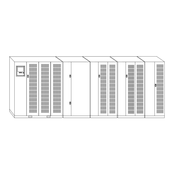
Page 112: Figure A-1. Typical Powerware 9315 (500-750 Kva) Ups System
625 kVA 480/480, 600/600 109 (27.5) 750 kVA 480/480, 600/600 130.8 (33) Output/Inverter Cabinet Input/Rectifier Cabinet Figure A-1. Typical Powerware 9315 (500–750 kVA) UPS System ® EATON Powerware 9315 UPS (500–750 kVA) Installation and Operation Manual 164201691 Rev 1 www.powerware.com... -
Page 113: Figure A-2. Inverter/Rectifier Cabinet - Pcm 1 Dimensions
364.4 171.0 171.0 364.4 [14.3] [6.7] [6.7] [14.3] 1600 [63] FRONT VIEW DIMENSIONS ARE IN MILLIMETERS [INCHES] Figure A-2. Inverter/Rectifier Cabinet – PCM 1 Dimensions ® EATON Powerware 9315 UPS (500–750 kVA) Installation and Operation Manual 164201691 Rev 1 www.powerware.com... -
Page 114: Figure A-3. Inverter/Rectifier Cabinet - Pcm 1 Dimensions (Continued)
PUNCH CONDUIT HOLES.) TOP VIEW LEFT VIEW 970.0 [38.2] 47.0 DIMENSIONS ARE IN MILLIMETERS [INCHES] [1.9] 1004.9 [39.6] Figure A-3. Inverter/Rectifier Cabinet – PCM 1 Dimensions (continued) ® EATON Powerware 9315 UPS (500–750 kVA) Installation and Operation Manual 164201691 Rev 1 www.powerware.com... -
Page 115: Figure A-4. Output/Inverter Cabinet - Pcm 2 Dimensions
171.0 364.4 364.4 171.0 [6.7] [14.3] [14.3] [6.7] 1600 [63] FRONT VIEW DIMENSIONS ARE IN MILLIMETERS [INCHES] Figure A-4. Output/Inverter Cabinet – PCM 2 Dimensions ® EATON Powerware 9315 UPS (500–750 kVA) Installation and Operation Manual 164201691 Rev 1 www.powerware.com... -
Page 116: Figure A-5. Output/Inverter Cabinet - Pcm 2 Dimensions (Continued)
(REMOVE PANEL TO DRILL OR PUNCH CONDUIT HOLES.) TOP VIEW 970.0 [38.2] 47.0 [1.9] 1004.9 DIMENSIONS ARE IN MILLIMETERS [INCHES] [39.6] LEFT VIEW Figure A-5. Output/Inverter Cabinet – PCM 2 Dimensions (continued) ® EATON Powerware 9315 UPS (500–750 kVA) Installation and Operation Manual 164201691 Rev 1 www.powerware.com... -
Page 117: Figure A-6. Mbc - Pcm 3 Dimensions
INSTALLATION REFERENCE 2080.0 38.2] 558.8 [22.0] FRONT VIEW DIMENSIONS ARE IN MILLIMETERS [INCHES] Figure A-6. MBC – PCM 3 Dimensions ® EATON Powerware 9315 UPS (500–750 kVA) Installation and Operation Manual 164201691 Rev 1 www.powerware.com... -
Page 118: Figure A-7. Mbc - Pcm 3 Dimensions (Continued)
CONDUIT HOLES.) DOOR TOP VIEW 970.0 33.0 [38.2] [1.3] 1004.9 DIMENSIONS ARE IN MILLIMETERS [INCHES] [39.6] LEFT VIEW Figure A-7. MBC – PCM 3 Dimensions (continued) ® EATON Powerware 9315 UPS (500–750 kVA) Installation and Operation Manual 164201691 Rev 1 www.powerware.com... -
Page 119: Ups System Oneline Configurations
PW9315-750/625 600/600 600/600 PW9315-750/750 PW9315-625/500 400/400 400/400 PW9315-625/625 PW9315-750/625 Multi-Module – Parallel Multi-Module – Parallel Figure A-9 480/480 480/480 Capacity/Redundant PW9315-750/750 PW9315-750/625 600/600 600/600 PW9315-750/750 ® EATON Powerware 9315 UPS (500–750 kVA) Installation and Operation Manual 164201691 Rev 1 www.powerware.com... -
Page 120: Figure A-8. Single Module Ups System Oneline Drawing (480/480V And 600/600V Input/Output)
UPS is to be connected to ground. Figure A-8. Single Module UPS System Oneline Drawing (480/480V and 600/600V Input/Output) A-10 ® EATON Powerware 9315 UPS (500–750 kVA) Installation and Operation Manual 164201691 Rev 1 www.powerware.com... -
Page 121: Figure A-9. Multi-Module Ups System Oneline Drawing (With Powerware Hot Sync Capacity, 480/480V And 600/600V Input/Output)
3 PHASE, 3 OR 4 WIRE chassis ground. Figure A-9. Multi-Module UPS System Oneline Drawing (with Powerware Hot Sync Capacity, 480/480V and 600/600V Input/Output) ® A-11 EATON Powerware 9315 UPS (500–750 kVA) Installation and Operation Manual 164201691 Rev 1 www.powerware.com... -
Page 122: Power Wiring Installation Notes
UPS is to be connected to chassis ground. See Section I for installation instructions. A-12 ® EATON Powerware 9315 UPS (500–750 kVA) Installation and Operation Manual 164201691 Rev 1 www.powerware.com... - Page 123 (3) Phases, (1) Neutral, (1) Ground Minimum Conductor Size AWG or kcmil Number per Phase (each) NOTE Callout letters A, B, C, D, and E map to Figure A-8. ® A-13 EATON Powerware 9315 UPS (500–750 kVA) Installation and Operation Manual 164201691 Rev 1 www.powerware.com...
- Page 124 (3) Phases, (1) Neutral, (1) Ground Minimum Conductor Size AWG or kcmil Number per Phase (each) NOTE Callout letters A, B, C, D, and E map to Figure A-8. A-14 ® EATON Powerware 9315 UPS (500–750 kVA) Installation and Operation Manual 164201691 Rev 1 www.powerware.com...
- Page 125 (3) Phases, (1) Neutral, (1) Ground Minimum Conductor Size AWG or kcmil Number per Phase (each) NOTE Callout letters A, B, C, D, and E map to Figure A-8. ® A-15 EATON Powerware 9315 UPS (500–750 kVA) Installation and Operation Manual 164201691 Rev 1 www.powerware.com...
- Page 126 2-hole barrel lugs. See Table H for power cable terminations, Table I for conduit requirements, and Table J for recommended installation parts and tools not supplied by Eaton. Section A.4 shows the location of the power cable terminals inside the UPS.
- Page 127 AC Input to MBC (A, B, C, Ground) 3” PW9315 625/400 PW9315-625/400 Output (A, B, C, Neutral, Ground) 3” PW9315-625/450 PW9315 625/450 Battery 3.5” (Positive, Negative, Ground) ® A-17 EATON Powerware 9315 UPS (500–750 kVA) Installation and Operation Manual 164201691 Rev 1 www.powerware.com...
-
Page 128: Figure A-10. Securing Cables
INSTALLATION REFERENCE Table J. Recommended Installation Parts and Tool (Not Supplied by Eaton) Part Size Quantity Manufacturer Part Number Notes As required Color Code: Brown Long Barrel 2 Hole Lug 500 MCM Thomas & Betts 54876BE Die Code: 87 ×... - Page 129 20. Output overcurrent protection and output disconnect switch are to be provided by the user. Table L lists the maximum rating for continuous duty rated output circuit breakers satisfying the criteria for both. ® A-19 EATON Powerware 9315 UPS (500–750 kVA) Installation and Operation Manual 164201691 Rev 1 www.powerware.com...
- Page 130 27. The battery wiring used between the battery and the UPS should not allow a voltage drop of more than 1% of nominal DC voltage at rated battery current. A-20 ® EATON Powerware 9315 UPS (500–750 kVA) Installation and Operation Manual 164201691 Rev 1 www.powerware.com...
-
Page 131: Figure A-11. Cb2Tb To Dc Source Disconnect Device
CB2 AUX #1 NOT USED NOT USED CNT-120 VAC CNT-NEUT S.T. RTN-24 VDC S.T. RTN-24 VDC Figure A-11. CB2TB to DC Source Disconnect Device ® A-21 EATON Powerware 9315 UPS (500–750 kVA) Installation and Operation Manual 164201691 Rev 1 www.powerware.com... -
Page 132: Location Of Ups Terminals
NOTE Metal shield covering power wiring terminals and battery compartment must be removed to gain access to wiring terminals. Figure A-12. Inverter/Rectifier Cabinet – PCM 1 Terminals A-22 ® EATON Powerware 9315 UPS (500–750 kVA) Installation and Operation Manual 164201691 Rev 1 www.powerware.com... -
Page 133: Figure A-13. Inverter/Rectifier Cabinet - Pcm 1 Terminals (Continued)
ACCESS PANEL (POS) DC SOURCE INPUT (NEG) (ØA) (ØB) AC SOURCE INPUT (ØC) REAR LEFT SIDE Figure A-13. Inverter/Rectifier Cabinet – PCM 1 Terminals (continued) ® A-23 EATON Powerware 9315 UPS (500–750 kVA) Installation and Operation Manual 164201691 Rev 1 www.powerware.com... -
Page 134: Figure A-14. Output/Inverter Cabinet - Pcm 2 Terminals
NOTE Metal shield covering power wiring terminals and battery compartment must be removed to gain access to wiring terminals. Figure A-14. Output/Inverter Cabinet – PCM 2 Terminals A-24 ® EATON Powerware 9315 UPS (500–750 kVA) Installation and Operation Manual 164201691 Rev 1 www.powerware.com... -
Page 135: Figure A-15. Output/Inverter Cabinet - Pcm 2 Terminals (Continued)
NOTE Metal shield covering power wiring terminals and battery compartment must be removed to gain access to wiring terminals. Figure A-15. Output/Inverter Cabinet – PCM 2 Terminals (continued) ® A-25 EATON Powerware 9315 UPS (500–750 kVA) Installation and Operation Manual 164201691 Rev 1 www.powerware.com... -
Page 136: Figure A-16. Mbc - Pcm 3 Terminals
(E9, E10, E11) (A, B, C) BACKFEED PROTECTION SYSTEM BREAKER (FBP) BYPASS BREAKER STATIC SWITCH LEFT SIDE FRONT Figure A-16. MBC – PCM 3 Terminals A-26 ® EATON Powerware 9315 UPS (500–750 kVA) Installation and Operation Manual 164201691 Rev 1 www.powerware.com... -
Page 137: Figure A-17. Mbc - Pcm 3 Terminals (Continued)
MBC – TOP AND BUS BARS AC INPUT FROM AC INPUT INVERTER CABINET AC OUTPUT TO BYPASS TO LOAD TOP VIEW Figure A-17. MBC – PCM 3 Terminals (continued) ® A-27 EATON Powerware 9315 UPS (500–750 kVA) Installation and Operation Manual 164201691 Rev 1 www.powerware.com... -
Page 138: Customer Interface Wiring Notes
Breaker charge power. Control - Neutral Shunt Trip - 24 Vdc Open circuit breaker CB2 signal. it b CB2 i Shunt Trip - 24 Vdc A-28 ® EATON Powerware 9315 UPS (500–750 kVA) Installation and Operation Manual 164201691 Rev 1 www.powerware.com... -
Page 139: Figure A-18. Inverter/Rectifier Cabinet - Pcm 1 Customer Interface Wiring
NO SYNC RETURN NO SYNC OPEN FILTER - RETURN OPEN FILTER BATJ4 Battery I/O Board Figure A-18. Inverter/Rectifier Cabinet – PCM 1 Customer Interface Wiring ® A-29 EATON Powerware 9315 UPS (500–750 kVA) Installation and Operation Manual 164201691 Rev 1 www.powerware.com... -
Page 140: Figure A-19. Inverter/Rectifier Cabinet - Pcm 1 Customer Interface Wiring (Continued)
INSTALLATION REFERENCE RS-485 RS-232 X-SLOT CARD Figure A-19. Inverter/Rectifier Cabinet – PCM 1 Customer Interface Wiring (continued) A-30 ® EATON Powerware 9315 UPS (500–750 kVA) Installation and Operation Manual 164201691 Rev 1 www.powerware.com... -
Page 141: Figure A-20. Inverter/Rectifier Cabinet - Pcm 1 Customer Interface Wiring (Continued)
INSTALLATION REFERENCE CUSTOMER INTERFACE PANEL (X-SLOT) Figure A-20. Inverter/Rectifier Cabinet – PCM 1 Customer Interface Wiring (continued) ® A-31 EATON Powerware 9315 UPS (500–750 kVA) Installation and Operation Manual 164201691 Rev 1 www.powerware.com... - Page 142 UPS Remote to UPS Return Not Used REPO Dry contact used to activate REPO of UPS. ti t REPO f UPS REPO Common A-32 ® EATON Powerware 9315 UPS (500–750 kVA) Installation and Operation Manual 164201691 Rev 1 www.powerware.com...
-
Page 143: Figure A-21. Output/Inverter Cabinet - Pcm 2 Customer Interface Wiring
Building Alarm 2, and so on, on the monitor panel. Use twisted-pair wires for each alarm input and common. Figure A-21. Output/Inverter Cabinet – PCM 2 Customer Interface Wiring ® A-33 EATON Powerware 9315 UPS (500–750 kVA) Installation and Operation Manual 164201691 Rev 1 www.powerware.com... - Page 144 CB4- Aux #2* Not Used Not Used Not Used REPO Dry contact used to activate REPO of UPS. ti t REPO f UPS REPO Common A-34 ® EATON Powerware 9315 UPS (500–750 kVA) Installation and Operation Manual 164201691 Rev 1 www.powerware.com...
-
Page 145: Figure A-22. Mbc - Pcm 3 Customer Interface Wiring (Single Module System Only)
BUILDING ALARM #3 BUILDING ALARM #2 RETURN BUILDING ALARM #2 CUSTJ4 Figure A-22. MBC – PCM 3 Customer Interface Wiring (Single Module System Only) ® A-35 EATON Powerware 9315 UPS (500–750 kVA) Installation and Operation Manual 164201691 Rev 1 www.powerware.com... -
Page 146: Typical Repo
NOTE REPO switch rating is 24 Vdc, 1A minimum if supplied by the customer. The REPO switch must be a latching-type switch with a dedicated circuit. Twisted REPO CUSTTB Wires (2) Switch Figure A-24. REPO Wiring A-36 ® EATON Powerware 9315 UPS (500–750 kVA) Installation and Operation Manual 164201691 Rev 1 www.powerware.com... -
Page 147: Figure A-25. Typical Repo Switch
KNOCKOUT PATTERN Knockout Pattern TYPICAL 5 SIDES Typical 5 Sides TO UPS TO OTHER EQUIPMENT DIMENSIONS ARE IN MILLIMETERS [INCHES] Figure A-25. Typical REPO Switch ® A-37 EATON Powerware 9315 UPS (500–750 kVA) Installation and Operation Manual 164201691 Rev 1 www.powerware.com... -
Page 148: Rmp Dimensions And Mounting Details
MAX. DISTANCE BETWEEN RMP AND UPS NOT TO TWISTED (14–18 AWG) EXCEED 500 FT. DIMENSIONS ARE IN MILLIMETERS [INCHES] Figure A-26. RMP Dimensions and Mounting Details A-38 ® EATON Powerware 9315 UPS (500–750 kVA) Installation and Operation Manual 164201691 Rev 1 www.powerware.com... -
Page 149: Rim Dimensions And Mounting Details
MAX. WIRE SIZE: NO. 14 AWG MAX. WIRE SIZE: NO. 18 AWG DIMENSIONS ARE IN MILLIMETERS [INCHES] Figure A-27. RIM Dimensions and Mounting Details ® A-39 EATON Powerware 9315 UPS (500–750 kVA) Installation and Operation Manual 164201691 Rev 1 www.powerware.com... -
Page 150: Figure A-28. Rim Dimensions And Mounting Details (Continued)
74.6 [2.94] 215.9 171.5 [8.50] [6.75] KNOCKOUTS PROVIDED ON 5 SURFACES DIMENSIONS ARE IN MILLIMETERS [INCHES] Figure A-28. RIM Dimensions and Mounting Details (continued) A-40 ® EATON Powerware 9315 UPS (500–750 kVA) Installation and Operation Manual 164201691 Rev 1 www.powerware.com... -
Page 151: Scm Dimensions And Mounting Details
MAX. DISTANCE BETWEEN SCM AND UPS NOT TO TWISTED (14–18 AWG) EXCEED 500 FT. DIMENSIONS ARE IN MILLIMETERS [INCHES] Figure A-29. SCM Dimensions and Mounting Details ® A-41 EATON Powerware 9315 UPS (500–750 kVA) Installation and Operation Manual 164201691 Rev 1 www.powerware.com... -
Page 152: A.10 Battery Disconnect Switch Dimensions
“OFF” POSITION REMOVABLE FEET (IF WALL MOUNTED) 14.3 MTG [0.56] 342.95 [13.5] 806.5 [31.75] DIMENSIONS ARE IN MILLIMETERS [INCHES] Figure A-30. Battery Disconnect Switch Dimensions A-42 ® EATON Powerware 9315 UPS (500–750 kVA) Installation and Operation Manual 164201691 Rev 1 www.powerware.com... - Page 154 *1642016911* 164201691 1...
Need help?
Do you have a question about the POWERWARE 9315 and is the answer not in the manual?
Questions and answers