Bosch VIDEOJET X20 Installation & Operating Manual
Hide thumbs
Also See for VIDEOJET X20:
- Installation and operating manual (130 pages) ,
- Quick installation manual (13 pages)
Table of Contents
Advertisement
Quick Links
Advertisement
Table of Contents

Related Manuals for Bosch VIDEOJET X20


Summary of Contents for Bosch VIDEOJET X20
- Page 1 Network Video Server Installation and Operating Manual...
-
Page 3: Table Of Contents
Display Stamping Password Language Date/Time Time Server 5.10 Picture Settings 5.11 Encoder Profile 5.12 Profile Configuration 5.13 Video Input 5.14 Audio 5.15 JPEG Posting 5.16 Storage Medium 5.17 iSCSI 5.18 Partitioning Bosch Security Systems Installation and Operating Manual V3.5 | 2007.12... - Page 4 Testing the Network Connection Unit Reset Repairs Transfer and Disposal Appendix Troubleshooting General Malfunctions Malfunctions with iSCSI Connections LEDs Processor Load Serial Interface Terminal Block Communication with Terminal Program Glossary V3.5 | 2007.12 Installation and Operating Manual Bosch Security Systems...
- Page 5 VideoJet X20 Table of Contents | en Specifications 10.1 Unit 10.2 Protocols/Standards Index Bosch Security Systems Installation and Operating Manual V3.5 | 2007.12...
- Page 6 | Table of Contents VideoJet X20 V3.5 | 2007.12 Installation and Operating Manual Bosch Security Systems...
-
Page 7: Preface
Various functions can be triggered automatically by incorporating external alarm sensors. Other applications are not permitted. In the event of questions concerning the use of the unit which are not answered in this manual, please contact your sales partner or: Bosch Sicherheitssysteme GmbH Robert-Koch-Straße 100 85521 Ottobrunn Germany www.bosch-sicherheitssysteme.de... -
Page 8: Eu Directives
For exact identification, the model name and serial number are inscribed on the bottom of the housing. Please make a note of this information before installation if necessary so as to have it to hand in case of questions or when ordering spare parts. V3.5 | 2007.12 Installation and Operating Manual Bosch Security Systems... -
Page 9: Safety Information
– If safe operation of the unit cannot be ensured, remove it from service and secure it to prevent unauthorized operation. In such cases, have the unit checked by Bosch Security Systems. Safe operation is no longer possible in the following cases: –... - Page 10 | Safety Information VideoJet X20 V3.5 | 2007.12 Installation and Operating Manual Bosch Security Systems...
-
Page 11: Product Description
Sun JVM – Adobe Acrobat Reader NOTICE! Check that the delivery is complete and in perfect condition. Have your unit checked by Bosch Security Systems if you detect any damage. Bosch Security Systems Installation and Operating Manual V3.5 | 2007.12... -
Page 12: System Requirements
Additional Operational Requirements – Microsoft Internet Explorer (version 6.0 or higher) – Receiver software, for example VIDOS (version 3.11 or higher) or Bosch Video Management System – MPEG-4 compatible hardware decoder from Bosch Security Systems (for example VIP XD) as a receiver and connected video monitor –... -
Page 13: Overview Of Functions
The VideoJet X20 offers a variety of options for protection against unauthorized reading. Web browser connections can be protected using HTTPS. You can protect the control channels via the SSL encryption protocol. With an additional license, the user data itself can be encrypted. Bosch Security Systems Installation and Operating Manual V3.5 | 2007.12... -
Page 14: Remote Control
Integrated Network Switch The integrated switch functionality of the VideoJet X20 permits the ETH 1, ETH 2 and SFP interfaces to be used alternatively, redundantly or for cascading other units. V3.5 | 2007.12 Installation and Operating Manual Bosch Security Systems... - Page 15 Flexible encryption of control and data channels – Authentication according to international standard 802.1x – Transmission and receipt of audio signals – Bidirectional audio (mono) for line connections – Audio encoding to international standard G.711 Bosch Security Systems Installation and Operating Manual V3.5 | 2007.12...
-
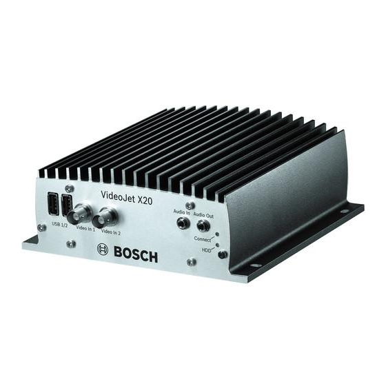
Page 16: Connections On The Front Panel
Connect LED flashes green when the unit is connected to a video HDD LED flashes orange when hard drive activity is detected (only on units with a hard drive installed) V3.5 | 2007.12 Installation and Operating Manual Bosch Security Systems... -
Page 17: Connections On The Rear Panel
SFP SFP slot for mini-GBIC module NOTICE! For more information about the LEDs, see Section 8.4 LEDs, page 114. For terminal block assignment, see Section 8.7 Terminal Block, page 116. Bosch Security Systems Installation and Operating Manual V3.5 | 2007.12... - Page 18 | Product Description VideoJet X20 V3.5 | 2007.12 Installation and Operating Manual Bosch Security Systems...
-
Page 19: Installation
For mounting on concrete, use screws with the following minimum specification: M4 × 40 mm (1.57 in) and 6 mm (0.23 in) plastic dowels, for example fischer S4, type 50106. Bosch Security Systems Installation and Operating Manual V3.5 | 2007.12... -
Page 20: Connections
Connect the VideoJet X20 to the network via the ETH 1 socket. Connect the VideoJet X20 to a redundant switch or hub on the same network via the ETH 2 socket. V3.5 | 2007.12 Installation and Operating Manual Bosch Security Systems... - Page 21 For ETH 1 or ETH 2 connections, use a UTP category 5 network cable with RJ45 plugs. NOTICE! You can obtain a list of compatible iSCSI systems from your supplier or directly from Bosch Security Systems. This list is constantly being updated and extended. 4.3.6...
-
Page 22: Data Interface
If possible, use a bounce-free contact system as the actuator. Connect the lines to the appropriate terminals on the orange terminal block (IN1 to IN4) and check that the connection is secure. V3.5 | 2007.12 Installation and Operating Manual Bosch Security Systems... -
Page 23: Relay Outputs
Connect the LED lines to the appropriate terminals on the orange terminal block (RM1 and RM2) and check that the connection is secure. Check that the signals on the Connect LED on the VideoJet X20 and the remote indicator LED correspond. Bosch Security Systems Installation and Operating Manual V3.5 | 2007.12... - Page 24 Connect the + (plus) line on the car battery to the BP terminal on the orange terminal block. Connect the – (minus) line on the car battery to the GND terminal on the orange terminal block. Now check that the connections are secure. V3.5 | 2007.12 Installation and Operating Manual Bosch Security Systems...
-
Page 25: Power On/Power Off
Insert the CD into the computer's CD-ROM drive. If the CD does not start automatically, open the Configuration Manager directory using Windows Explorer and double-click Setup.exe. Follow the on-screen instructions. Bosch Security Systems Installation and Operating Manual V3.5 | 2007.12... - Page 26 4.5.4 Additional Parameters You can check and set additional parameters with the assistance of the Configuration Manager. You can find detailed information on this in the documentation for this program. V3.5 | 2007.12 Installation and Operating Manual Bosch Security Systems...
-
Page 27: Configuration Using A Web Browser
Insert the product CD into the computer's CD-ROM drive. If the CD does not start automatically, open the root directory of the CD in Windows Explorer and double-click MPEGAx.exe. Follow the on-screen instructions. Bosch Security Systems Installation and Operating Manual V3.5 | 2007.12... - Page 28 If you do not connect, the unit may have reached its maximum number of connections. Depending on the unit and network configuration, each VideoJet X20 can have up to 25 Web browser connections or up to 50 connections via VIDOS or Bosch Video Management System. V3.5 | 2007.12...
-
Page 29: Configuration Menu
The settings in the configuration menu should only be processed or modified by expert users or system support personnel. All settings are stored in the VideoJet X20's memory so that they are retained even if the power supply is interrupted. Bosch Security Systems Installation and Operating Manual V3.5 | 2007.12... - Page 30 After each change, click Set to save the change. CAUTION! Save each change with the associated Set button. Clicking the Set button saves the settings only in the current field. Changes in any other fields are ignored. V3.5 | 2007.12 Installation and Operating Manual Bosch Security Systems...
-
Page 31: Identification
VIDOS or Bosch Video Management System programs. The unit name is used for the remote identification of a unit, in the event of an alarm for example. -
Page 32: Display Stamping
If you select the Custom option, additional fields are displayed where you can specify the exact position (Position (XY)). In the Position (XY) fields, enter the values for the desired position. V3.5 | 2007.12 Installation and Operating Manual Bosch Security Systems... -
Page 33: Alarm Message
Select On if you wish the transmitted video images to be "watermarked". After activation, all images are marked with a green W. A red W indicates that the sequence (live or saved) has been manipulated. Bosch Security Systems Installation and Operating Manual V3.5 | 2007.12... -
Page 34: Password
The new password is only saved when you click the Set button. You should therefore click the Set button immediately after entering and confirming a password, even if you also wish to subsequently assign a password to another user name. V3.5 | 2007.12 Installation and Operating Manual Bosch Security Systems... -
Page 35: Language
The VideoJet X20 can receive the time signal from a time server using various time server protocols, and then use it to set the internal clock. The unit polls the time signal automatically once every minute. Bosch Security Systems Installation and Operating Manual V3.5 | 2007.12... -
Page 36: Daylight Saving Time
SNTP server as the protocol. This supports a high level of accuracy and is required for special applications and subsequent function extensions. Select Time server for a time server that works with the protocol RFC 868. V3.5 | 2007.12 Installation and Operating Manual Bosch Security Systems... -
Page 37: Picture Settings
Also observe the processor load indicator that appears at the top of the window near the manufacturer's logo (see Section 8.5 Processor Load, page 115). Bosch Security Systems Installation and Operating Manual V3.5 | 2007.12... -
Page 38: Encoder Profile
Profile 7: Modem For analog modem connections with 20 kbps, resolution 352 × 288/240 pixels – Profile 8: GSM For GSM connections at 9,600 baud, resolution 176 × 144/120 pixels V3.5 | 2007.12 Installation and Operating Manual Bosch Security Systems... - Page 39 Check the box for the required data stream. Bosch Security Systems Installation and Operating Manual V3.5 | 2007.12...
-
Page 40: Profile Configuration
5.12.1 Profile name You can enter a new name for the profile here. The name is then displayed in the list of available profiles in the Active profile field. V3.5 | 2007.12 Installation and Operating Manual Bosch Security Systems... -
Page 41: Target Data Rate
The value entered here must be at least 10% higher than the value entered in the Target data rate field. If the value entered here is too low, it will automatically be adjusted. Bosch Security Systems Installation and Operating Manual... - Page 42 A value of 31 results in a very high refresh rate and lower image quality. V3.5 | 2007.12 Installation and Operating Manual Bosch Security Systems...
-
Page 43: Video Input
PLL as a result of jitter effects caused by the mechanical components of a VCR. NOTICE! In some cases, selecting the VCR option can lead to an improvement in the video image even with a camera connected. Bosch Security Systems Installation and Operating Manual V3.5 | 2007.12... -
Page 44: Audio
5.14.3 Selection Click one of the option boxes and then click Set to display the level of the respective audio input for orientation and to set the gain. V3.5 | 2007.12 Installation and Operating Manual Bosch Security Systems... -
Page 45: Jpeg Posting
The date and time are automatically added to the file name. When setting this parameter, ensure that the unit's date and time are always correctly set. Example: the file snap011005_114530.jpg was stored on October 1, 2005 at 11:45 and 30 seconds. Bosch Security Systems Installation and Operating Manual V3.5 | 2007.12... - Page 46 Click the checkbox to activate the camera input for the JPEG image. An enabled camera input is indicated by a check mark. NOTICE! The numbering follows the labeling of the video inputs on the actual unit. V3.5 | 2007.12 Installation and Operating Manual Bosch Security Systems...
-
Page 47: Storage Medium
It is also possible to let the Video Recording Manager (VRM) control all recording when accessing an iSCSI system. The VRM is an external program for configuring recording tasks for video servers. For further information please contact your local customer service at Bosch Security Systems. -
Page 48: Iscsi
Enter the IP address of the required iSCSI target here. Click the Read button. The connection to the IP address will be established. The iSCSI LUN Map field contains the corresponding logical drives. V3.5 | 2007.12 Installation and Operating Manual Bosch Security Systems... - Page 49 The initiator name is automatically displayed after a connection has been established. 5.17.8 Initiator extension Enter the initiator extension. For the sake of clarity, you can enter a name or the existing extension with a comment, for example "– Camera 2". Bosch Security Systems Installation and Operating Manual V3.5 | 2007.12...
- Page 50 Click Log to view a status report with logged actions. A new window will open. In this window, click Clear to delete all entries. The entries will be deleted immediately. This action cannot be reversed. Click the Close button to close the window. V3.5 | 2007.12 Installation and Operating Manual Bosch Security Systems...
-
Page 51: Partitioning
In addition, the page provides you with an overview of the drive data; for example total memory and number of partitions created. A pie chart indicates how much memory space is partitioned for recordings. Bosch Security Systems Installation and Operating Manual V3.5 | 2007.12... -
Page 52: Creating A Partition
Click the Next > button at the bottom of the window to continue with the next step. Click the < Back button at the bottom of the window to view the previous step again. Click the Cancel button to cancel the process and close the wizard. V3.5 | 2007.12 Installation and Operating Manual Bosch Security Systems... - Page 53 Click the Partition status button. A new window with the entries for the selected partition is opened. Click the << and >> buttons to view the status of other partitions. Click OK to close the window. Bosch Security Systems Installation and Operating Manual V3.5 | 2007.12...
-
Page 54: Editing A Partition
In the case of Linear mode the recording proceeds until the entire hard drive space is full. The recording is then stopped until old recordings have been deleted. V3.5 | 2007.12 Installation and Operating Manual Bosch Security Systems... -
Page 55: Alarm Track Size
Click the Delete all partitions button. The display retains the lines containing the numbers, the partition names are deleted and 0 is specified as the size in each case. Bosch Security Systems Installation and Operating Manual V3.5 | 2007.12... -
Page 56: Recording Profiles
A new window will open and you can select the profiles in which you want to copy the settings. For each profile, click the Set button to save the settings in the unit. V3.5 | 2007.12 Installation and Operating Manual Bosch Security Systems... -
Page 57: Standard Profile
The numbering of the checkboxes for the alarm inputs corresponds to the labeling of the alarm inputs on the VideoJet X20. The motion and video alarm corresponds to the labeling on the video inputs. Bosch Security Systems Installation and Operating Manual V3.5 | 2007.12... -
Page 58: Recording Scheduler
Click the Select all button to link all time intervals to the selected profile. Click the Clear all button to deselect all of the intervals. When you are finished, click the Set button to save the settings in the unit. V3.5 | 2007.12 Installation and Operating Manual Bosch Security Systems... - Page 59 5.20.5 Recording status The graphic indicates the recording activity of the VideoJet X20. You will see an animated graphic while recording is taking place. Bosch Security Systems Installation and Operating Manual V3.5 | 2007.12...
-
Page 60: Alarm Sources
You can enter a name for each alarm input, which is then displayed below the icon for the alarm input on the LIVEPAGE if configured correctly (see Section 5.32 Livepage Configuration, page 85). V3.5 | 2007.12 Installation and Operating Manual Bosch Security Systems... -
Page 61: Alarm Connections
5.22.3 Destination IP address For each number, enter the corresponding IP address for the desired remote station. Bosch Security Systems Installation and Operating Manual V3.5 | 2007.12... - Page 62 VIDOS or Bosch Video Management System, you can store a general password here. The VideoJet X20 can use this general password to connect to all remote stations protected with the same password.
-
Page 63: Ssl Encryption
Depending on the system configuration, the receiver can then select the other cameras as well. NOTICE! The numbering follows the labeling of the video inputs on the actual unit. Bosch Security Systems Installation and Operating Manual V3.5 | 2007.12... -
Page 64: Vca
Click one of the tabs to open the configuration of the corresponding video input. Enter the desired settings. Click the Default button to return all settings to their default, if appropriate. V3.5 | 2007.12 Installation and Operating Manual Bosch Security Systems... - Page 65 NOTICE! Additional analysis algorithms with comprehensive functions such as IVMD and IVA are available from Bosch Security Systems. If you select one of these algorithms, you can set the corresponding parameters here directly. You can find information on this in the relevant documents on the product CD supplied (see Section 3.1 Scope of Delivery, page 11).
-
Page 66: Tamper Detection
The algorithm reacts to the differences between the reference image and the current video image. The darker the observation area, the higher the value that must be selected. V3.5 | 2007.12 Installation and Operating Manual Bosch Security Systems... - Page 67 Check the Reference check box to activate on-going matching. The stored reference image is displayed in black and white below the current video image, and the selected areas are marked in yellow. Bosch Security Systems Installation and Operating Manual V3.5 | 2007.12...
- Page 68 Right-click any fields you wish to deactivate. Click OK to save the configuration. Click the close button X in the window title bar to close the window without saving the changes. V3.5 | 2007.12 Installation and Operating Manual Bosch Security Systems...
-
Page 69: Alarm E-Mail
When a cellphone is used as the receiver, make sure to activate the e-mail or SMS function, depending on the format, so that these messages can be received. You can obtain information on operating your cellphone from your cellphone provider. Bosch Security Systems Installation and Operating Manual V3.5 | 2007.12... - Page 70 5.24.9 Test e-mail You can test the e-mail function by clicking the Send now button. An alarm e-mail is immediately created and sent. V3.5 | 2007.12 Installation and Operating Manual Bosch Security Systems...
-
Page 71: Alarm Task Editor
When you are finished, click the Set button to transmit the scripts to the unit. If the transfer was successful, the message Script successfully parsed is displayed over the text field. If it was not successful, an error message will be displayed with further information. Bosch Security Systems Installation and Operating Manual V3.5 | 2007.12... -
Page 72: Relay Settings
For example, if you want an alarm-activated lamp to stay on after the alarm ends, select Bistable. If you wish an alarm-activated siren to sound for ten seconds, for example, select 10 s. V3.5 | 2007.12 Installation and Operating Manual Bosch Security Systems... - Page 73 The Livepage can also be configured to display the name under the relay icon. 5.26.5 Trigger relay Click the button to trigger the relay manually (for testing or to operate a door opener, for example). Bosch Security Systems Installation and Operating Manual V3.5 | 2007.12...
-
Page 74: Com1
Transparent. Select Terminal if you wish to operate the unit from a terminal. NOTICE! After selecting a unit, the remaining parameters in the window are set automatically and should not be changed. V3.5 | 2007.12 Installation and Operating Manual Bosch Security Systems... -
Page 75: Baud Rate
Stop bits Select the number of stop bits per character. 5.27.6 Parity check Select the type of parity check. 5.27.7 Interface mode Select the required protocol for the serial interface. Bosch Security Systems Installation and Operating Manual V3.5 | 2007.12... -
Page 76: Network
The settings in this screen are used to integrate the VideoJet X20 into an existing network. Changes to fields followed by the Reboot link are transmitted to the unit by clicking the Set button; however, they will only be activated once the unit is rebooted. V3.5 | 2007.12 Installation and Operating Manual Bosch Security Systems... -
Page 77: Ip Address
Select a different HTTP browser port from the list if required. The default HTTP port is 80. If you want to allow only secure connections via HTTPS, you must deactivate the HTTP port. In this case, select Off. Bosch Security Systems Installation and Operating Manual V3.5 | 2007.12... - Page 78 The potential value depends on the network structure. A higher value is only useful if the iSCSI system is located in the same subnet as the VideoJet X20. V3.5 | 2007.12 Installation and Operating Manual Bosch Security Systems...
- Page 79 If a DHCP server is employed in the network for the dynamic assignment of IP addresses, you can activate acceptance of IP addresses automatically assigned to the VideoJet X20. Certain applications (VIDOS, Bosch Video Management System, Archive Player, Configuration Manager) use the IP address for the unique allocation of the unit. When using such...
-
Page 80: Multicasting
NOTICE! You must set the parameters for each encoder (video input) and for each stream individually. The numbering follows the labeling of the video inputs on the actual unit. V3.5 | 2007.12 Installation and Operating Manual Bosch Security Systems... - Page 81 You can enter a value to specify how long the multicast data packets are active on the network. This value must be greater than one if multicast is to be run via a router. Bosch Security Systems Installation and Operating Manual...
-
Page 82: Encryption
If you delete a key, the data for this channel will be transferred unencrypted. NOTICE! The encryption of video data requires increased computing power. V3.5 | 2007.12 Installation and Operating Manual Bosch Security Systems... - Page 83 Automatic key interchange You can activate automatic key interchange between two units (or unit and software decoder) over a secure connection. If the box is checked, keys will be automatically exchanged. Bosch Security Systems Installation and Operating Manual V3.5 | 2007.12...
-
Page 84: Version Information
You can select all required text on this page with the mouse and copy it to the clipboard with the [Ctrl]+[C] key combination, for example if you want to send it via e-mail. V3.5 | 2007.12 Installation and Operating Manual Bosch Security Systems... -
Page 85: Livepage Configuration
Internet/Intranet). When accessing via the Internet/Intranet, ensure that a connection is always available to display the image. The image file is not stored in the VideoJet X20. Bosch Security Systems Installation and Operating Manual V3.5 | 2007.12... - Page 86 5.32.4 Bilinx control Next to the field for view control at the top left of the LIVEPAGE, an additional field is displayed for the special Bosch Security Systems Bilinx control. 5.32.5 Show alarm inputs The alarm inputs are shown next to the video image as icons, along with their assigned names.
- Page 87 Path for JPEG and MPEG files Enter the path for the storage location of individual images and video sequences that you can save from the LIVEPAGE. If necessary, click Browse to find a suitable directory. Bosch Security Systems Installation and Operating Manual V3.5 | 2007.12...
-
Page 88: System State
You can enter the activation key to enable additional functions or software modules in this window. NOTICE! The activation key cannot be deactivated again and is not transferable to other units. V3.5 | 2007.12 Installation and Operating Manual Bosch Security Systems... -
Page 89: Maintenance
In the address bar of your browser, enter /main.htm after the IP address of the VideoJet X20 (for example 192.168.0.20/main.htm). Repeat the upload. Bosch Security Systems Installation and Operating Manual V3.5 | 2007.12... -
Page 90: Ssl Certificate
Maintenance log You can download an internal maintenance log from the unit to send it to Customer Service for support purposes. Click Download and select a storage location for the file. V3.5 | 2007.12 Installation and Operating Manual Bosch Security Systems... -
Page 91: Function Test
Does the VideoJet X20 transmit all the required data? – Does the VideoJet X20 respond to alarm events as required? – Do the recordings occur as intended? – Is it possible to control peripherals if necessary? Bosch Security Systems Installation and Operating Manual V3.5 | 2007.12... - Page 92 | Configuration Using a Web Browser VideoJet X20 V3.5 | 2007.12 Installation and Operating Manual Bosch Security Systems...
-
Page 93: Operation
Insert the product CD into the computer's CD-ROM drive. If the CD does not start automatically, open the root directory of the CD in Windows Explorer and double-click MPEGAx.exe. Follow the on-screen instructions. Bosch Security Systems Installation and Operating Manual V3.5 | 2007.12... - Page 94 Start the Web browser. Enter the VideoJet X20's IP address as the URL. The connection is established and after a short time you will see the LIVEPAGE with the video image. V3.5 | 2007.12 Installation and Operating Manual Bosch Security Systems...
-
Page 95: The Livepage
If you do not connect, the unit may have reached its maximum number of connections. Depending on the unit and network configuration, each VideoJet X20 can have up to 25 Web browser connections or up to 50 connections via VIDOS or Bosch Video Management System. 6.2.2... - Page 96 You can switch connected units using the relays in the VideoJet X20 (for example lights or door openers). To activate this, click the icon for the corresponding relay next to the video image. The icon will be red when the relay is activated. V3.5 | 2007.12 Installation and Operating Manual Bosch Security Systems...
- Page 97 When the connection maintaining voice contact with the VideoJet X20 is broken, the next user to connect to the VideoJet X20 can transmit the audio data to the VideoJet X20. Bosch Security Systems Installation and Operating Manual V3.5 | 2007.12...
-
Page 98: Saving Snapshots
MPEG files, page 87). A red dot in the icon indicates that recording is in progress. Click the icon again to stop recording. NOTICE! You can play back saved video sequences using the Player from Bosch Security Systems, which can be installed from the product CD supplied (see Section 3.1 Scope of Delivery, page 11). -
Page 99: Running Recording Program
You can ascertain from the Dual Video view for which camera a recording is running by moving the mouse cursor over the icon. A message is displayed below the mouse cursor. Bosch Security Systems Installation and Operating Manual V3.5 | 2007.12... -
Page 100: The Recordings Page
Click a partition name from the list to display the recordings for this partition. Click a list entry. The playback for the selected sequence starts immediately in the video window. V3.5 | 2007.12 Installation and Operating Manual Bosch Security Systems... -
Page 101: Controlling A Playback
Start or pause playback Jump to the start of the active video sequence or to the previous sequence in the list Jump to the start of the next video sequence in the list Bosch Security Systems Installation and Operating Manual V3.5 | 2007.12... - Page 102 NOTICE! Bookmarks are only valid while you are in the RECORDINGS page; they are not saved with the sequences. As soon as you leave the page all bookmarks are deleted. V3.5 | 2007.12 Installation and Operating Manual Bosch Security Systems...
-
Page 103: Backup
Click a preview in the Screenshots area. A new window will open. Click the Print button to start the printing process. Click the close button X in the window title bar to close the window again. Bosch Security Systems Installation and Operating Manual V3.5 | 2007.12... -
Page 104: Installing The Player
104 en | Operation VideoJet X20 Installing the Player You can play back saved video sequences using the Player from Bosch Security Systems, which can be found on the product CD supplied (see Section 3.1 Scope of Delivery, page 11). NOTICE! In order to play back saved sequences using the Player, suitable MPEG ActiveX software must be installed on the computer. -
Page 105: Hardware Connections Between Video Servers
This option can also be used to connect a sender and a compatible receiver using a switch connected to the alarm input. You do not need a computer to make the connection in this case. Bosch Security Systems Installation and Operating Manual V3.5 | 2007.12... - Page 106 Start the terminal program and enter the command 4 in the main menu to switch to the Rcp+ menu. In the Rcp+ menu, enter the command 5 to deactivate the automatic connection. V3.5 | 2007.12 Installation and Operating Manual Bosch Security Systems...
-
Page 107: Operation Using Software Decoders
Bosch CCTV products as one component of an extensive video security management system. It allows you to integrate your existing components into a simple-to-control system or into the entire Bosch range, benefiting from a complete security solution based on the latest technology and years of experience. - Page 108 108 en | Operation VideoJet X20 V3.5 | 2007.12 Installation and Operating Manual Bosch Security Systems...
-
Page 109: Maintenance And Upgrades
Connect LED flashes red (see Section 3.4 Connections on the Front Panel, page 16). All settings will revert to their defaults. Change the IP address of the VideoJet X20 if necessary. Configure the unit to meet your requirements. Bosch Security Systems Installation and Operating Manual V3.5 | 2007.12... -
Page 110: Repairs
The VideoJet X20 should only be passed on together with this installation and operating manual. Your Bosch product is designed and manufactured with high quality materials and components which can be recycled and reused. This symbol means that electrical and electronic equipment, at their end-of-life, should be disposed of separately from your household waste. -
Page 111: Appendix
If you are unable to resolve a malfunction, please contact your supplier or system integrator or go directly to Bosch Security Systems Customer Service. You can view a range of information about your unit version on the Version Information page (see Section 5.31 Version Information, page 84). -
Page 112: General Malfunctions
Check audio parameters on the Audio configuration and Livepage Configuration pages. The audio voice connection is Wait until the connection is free already in use by another and then call the sender again. receiver. V3.5 | 2007.12 Installation and Operating Manual Bosch Security Systems... -
Page 113: Malfunctions With Iscsi Connections
FAIL" appears below a network interface. node. LUN mapping is not Some iSCSI systems do not Delete the initiator extension on possible. support the use of an initiator the iSCSI configuration page. extension. Bosch Security Systems Installation and Operating Manual V3.5 | 2007.12... -
Page 114: Leds
VideoJet X20 is faulty, for example following failed firmware upload. 8.4.6 HDD LED Does not light up: No hard drive fitted. Lights up orange: Hard drive fitted. Flashes orange: Hard drive activity. V3.5 | 2007.12 Installation and Operating Manual Bosch Security Systems... -
Page 115: Processor Load
The serial interface supports the RS232, RS422 and RS485 transmission standards. The mode used depends on the current configuration (see Section 5.27 COM1, page 74). Connection is via the terminal block. Bosch Security Systems Installation and Operating Manual V3.5 | 2007.12... -
Page 116: Terminal Block
For the RM1 and RM2 contact specifications, see Section 4.3.10 Remote Indication of the Connection Status, page 23. For the backup power supply specifications, see Section 4.3.11 Backup Power Supply, page 24. V3.5 | 2007.12 Installation and Operating Manual Bosch Security Systems... -
Page 117: Communication With Terminal Program
Enter one command at a time. When you have entered a value (such as an IP address), check the characters you have entered before pressing Enter to transfer the values to the VideoJet X20. Bosch Security Systems Installation and Operating Manual V3.5 | 2007.12... - Page 118 8.8.6 Additional Parameters You can use the terminal program to check other basic parameters and modify them where necessary. Use the on-screen commands in the various submenus to do this. V3.5 | 2007.12 Installation and Operating Manual Bosch Security Systems...
-
Page 119: Glossary
This enables flexible operation of an interface as a Gigabit Ethernet via twisted-pair cables or fiber optic cables. Group of Pictures HTTP Hypertext Transfer Protocol: protocol for transmitting data over a network Bosch Security Systems Installation and Operating Manual V3.5 | 2007.12... - Page 120 A further development of MPEG-2 designed for transmitting audiovisual data at very low transfer rates (for example over the Internet) Maximum Segment Size; maximum byte figure for the user data in a data packet V3.5 | 2007.12 Installation and Operating Manual Bosch Security Systems...
- Page 121 SNTP Simple Network Time Protocol; a simplified version of NTP (see NTP) Secure Sockets Layer; an encryption protocol for data transmission in IP-based networks Subnet mask See Net mask Bosch Security Systems Installation and Operating Manual V3.5 | 2007.12...
- Page 122 User Datagram Protocol Uniform Resource Locator Unshielded Twisted Pair See Wide area network Wide area network A long distance link used to extend or connect remotely located local area networks V3.5 | 2007.12 Installation and Operating Manual Bosch Security Systems...
-
Page 123: Specifications
Dimensions (H × W × D) 61 × 160 × 178 mm / 2.4 × 6.3 × 7.0 in, including BNC connections Weight Approx. 1.5 kg / 3.3 lb, including HDD Bosch Security Systems Installation and Operating Manual V3.5 | 2007.12... - Page 124 RTP, Telnet, UDP, TCP, IP, HTTP, HTTPS, DHCP, IGMP V2, IGMP V3, ICMP, ARP, SNTP, SNMP (V1/V2c/V3 MIB-II), 802.1x Audio coding protocol G.711, 300 Hz to 3.4 kHz Audio sampling rate 8 kHz Audio data rate 80 kbps V3.5 | 2007.12 Installation and Operating Manual Bosch Security Systems...
- Page 125 48 Danger 9 JPEG format 45 Data bits 75 JPEG posting 45 Data interface 22 JPEG posting interval 46 Data terminal 117 Date 35 Language 35 Date format 35 Bosch Security Systems Installation and Operating Manual V3.5 | 2007.12...
- Page 126 Symbols 7 Processor load indicator 115 Synchronize 35 Product name 85 System log 87 Profile configuration 40 System requirements 12 Profiles 38 Protocol 75 Tamper detection 66 Target data rate 41 V3.5 | 2007.12 Installation and Operating Manual Bosch Security Systems...
- Page 127 Unit name 31 Unit reset 109 Unit time 35 URL 28 USB interface 16 User name 34 VCR 43 Video content analysis 64 Video input 16 Video sensor 64 Watermarking 33 Bosch Security Systems Installation and Operating Manual V3.5 | 2007.12...
- Page 128 128 en | Index VideoJet X20 V3.5 | 2007.12 Installation and Operating Manual Bosch Security Systems...
- Page 130 Bosch Security Systems Robert-Koch-Straße 100 D-85521 Ottobrunn Germany Telefon 089 6290-0 089 6290-1020 www.bosch-securitysystems.com © Bosch Security Systems, 2007...
Need help?
Do you have a question about the VIDEOJET X20 and is the answer not in the manual?
Questions and answers