Bosch Rexroth IndraControl XFE01.1-SY-01 Operating Instructions Manual
Safety extension module
Hide thumbs
Also See for Rexroth IndraControl XFE01.1-SY-01:
- Operating instructions manual (52 pages)

Related Manuals for Bosch Rexroth IndraControl XFE01.1-SY-01


Summary of Contents for Bosch Rexroth IndraControl XFE01.1-SY-01
- Page 1 IndraControl XFE01.1-SY-01 Safety Extension Module Operating Instructions Edition 04 R911376654...
- Page 2 Edition 04 2021-09 tab. 1-1 "Change record" on page 1 Copyright © Bosch Rexroth AG 2021 All rights reserved, also regarding any disposal, exploitation, reproduction, edit- ing, distribution, as well as in the event of applications for industrial property rights.
-
Page 3: Table Of Contents
Spare parts and accessories..............8 Accessories.................... 8 Wear parts..................... Ambient conditions................8 Technical data..................12 Voltage supply..................12 Safety-related characteristic values............. Dimensions and weight............... Standards.................... Standards used..................13 8.1.1 General standards................8.1.2 Safety standards.................. 14 TÜV certificate..................R911376654_Edition 04 Bosch Rexroth AG... - Page 4 SD card....................30 12.2 Operating and error displays............... 12.2.1 "Conf" pushbutton................12.2.2 LED...................... 12.2.3 LED on XD1 plug.................. 32 Troubleshooting and debugging............32 13.1 General information................32 Maintenance..................14.1 Cleaning notes..................14.2 Maintenance notes................33 Bosch Rexroth AG R911376654_Edition 04...
- Page 5 Replacing SD card................Ordering information................15.1 Type code..................... 34 15.2 Accessories and spare parts..............35 15.3 Ordering data ..................35 Disposal....................16.1 General information................35 16.2 Return....................35 16.3 Packaging..................... 35 Service and support................Index....................R911376654_Edition 04 Bosch Rexroth AG...
- Page 6 IndraControl XFE01.1-SY-01 Safety Ex- tension Module Bosch Rexroth AG R911376654_Edition 04...
-
Page 7: About This Documentation
Program Test Maintain Dispose Activities Design Install Configure Remove faults Construct Simulate Create the NC program Fig. 1-1: Assigning the present documentation to the target groups, product phases and ac- tivities of the target group R911376654_Edition 04 Bosch Rexroth AG... -
Page 8: Purpose
Creation and use of a safety application ● Basics of the data exchange between the safety applica- ● tion and the standard application of the IndraLogic XLC/ IndraMotion MLC/IndraMotion MTX 14VRS Information on diagnostics and troubleshooting ● Programming under SafeLogic ● Bosch Rexroth AG R911376654_Edition 04... -
Page 9: Customer Feedback
Please email your feedback on the documentations to Feed- back.Documentation@boschrexroth.de. Directly insert comments in the elec- tronic PDF document and send the PDF file to Bosch Rexroth. 2 Product identification and scope of deliv- 2.1 Product identification The Safety extension module IndraControl XFE01.1-SY-01 is connected to the... -
Page 10: Product Identification
24 V power connector XA-CN01 ● Bus base module XA-BS11 for IndraControl extension modules ● Safety instructions ● 3 Using safety instructions 3.1 Structure of the safety instructions The safety instructions are structured as follows: Bosch Rexroth AG R911376654_Edition 04... -
Page 11: Explaining Signal Words And Safety Alert Symbol
In case of non-compliance with this safety instruction, death or serious injury will occur. WARNING In case of non-compliance with this safety instruction, death or serious injury can occur. CAUTION In case of non-compliance with this safety instruction, minor or moderate injury can occur. R911376654_Edition 04 Bosch Rexroth AG... -
Page 12: Symbols Used
4 Intended use The Bosch Rexroth Safety extension module IndraControl XFE01.1-SY-01 is a safety component. It becomes only a safety-related control system (IndraMotion MLC SafeLogic) if used with a Rexroth IndraControl XM control. For information... - Page 13 The operation is not permitted for the following systems according to the follow- ing standards and guidelines: Lifts (directive 2006/42/EC) ● ATEX (directive 2014/34/EU) ● Burner control systems (DIN EN 298) ● Safety systems for unfired pressure vessels (DIN EN 764-7:2002/AC:2006) ● R911376654_Edition 04 Bosch Rexroth AG...
-
Page 14: Spare Parts And Accessories
≥ 86 °C – ture is high Switch-off if internal tempera- ≥ 89 °C – ture is high Overvoltage category – Protection class III, DIN EN 61010-2-201 – Tab. 6-1: Climatic ambient conditions and characteristics Bosch Rexroth AG R911376654_Edition 04... - Page 15 Increased noise level 1.4 GHz – 2.0 GHz: 10 V/m 2.0 GHz – 2.7 GHz: 3 V/m Fast transients (burst), standard Affected interfaces 1 kV Test acc. to DIN EN 61000-4-4 Supply voltage 2 kV R911376654_Edition 04 Bosch Rexroth AG...
- Page 16 EN 61000-6-2 as well as increased noise level acc. to EN 61326-3-1 NOTICE In case of overheating, the Safety extension module IndraControl XFE01.1-SY-01 goes into a safe Provide sufficient ventilation and cooling to ensure that the ambient temperature of the control does not exceed 55°C. Bosch Rexroth AG R911376654_Edition 04...
- Page 17 B (residential area and small enterprises) When using the product in residential areas or small enterprises, the operator has to take actions to prevent radio interferences (also re- fer to DIN EN 55022). R911376654_Edition 04 Bosch Rexroth AG...
-
Page 18: Technical Data
(average diagnostic coverage) Types of failure If the internal diagnostics of the Safety extension module IndraControl XFE01.1-SY-01 detects an error, the module goes into the safe state, that is, no more safe bus telegrams are sent Bosch Rexroth AG R911376654_Edition 04... -
Page 19: Dimensions And Weight
DIN EN 61131-2:2008 + Corr. 2009 Programmable controllers – EN 61131-2:2007 Part 2: Equipment requirements and tests IEC 61131-2:2017 DIN EN 61131-3:2014 Programmable controllers – IEC 61131-3:2013 Part 3: Programming languages Tab. 8-1: General standards R911376654_Edition 04 Bosch Rexroth AG... -
Page 20: Safety Standards
Electrical equipment for measurement, control and laborato- ry use – EN 61326-3-1:2017 EMC requirements – Part 3-1: Immunity requirements for safety-related systems and for equipment intended to perform safety-related func- tions (functional safety) – General industrial applications Tab. 8-2: Safety standards Bosch Rexroth AG R911376654_Edition 04... -
Page 21: Tüv Certificate
IndraControl XFE01.1-SY-01 Safety Ex- 15/41 tension Module Standards 8.2 TÜV certificate Fig. 8-1: TÜV certificate for IndraControl SafeLogic R911376654_Edition 04 Bosch Rexroth AG... -
Page 22: Ce Marking
UL and CSA marking applies only to the device upon delivery. After modifying the device, verify the UL and the CSA conformity. For the declaration of conformity, click on the following link for the media directory https://www.boschrexroth.com/MediaDirectory search for "DCTC-30131-003". Bosch Rexroth AG R911376654_Edition 04... -
Page 23: Interfaces
IndraControl XFE01.1-SY-01 Safety Ex- 17/41 tension Module Interfaces 9 Interfaces 9.1 Connection position Voltage supply Attached bus base module ① ③ SD card slot ② Fig. 9-1: Interfaces of the Safety extension module R911376654_Edition 04 Bosch Rexroth AG... -
Page 24: Sd Card Slot
For the position of the SD card slot, refer to fig. 9-1 "Interfaces of the Safety ex- tension module" on page If the SD card is removed during operation, the control goes into the safe state, i.e. the error response time. Bosch Rexroth AG R911376654_Edition 04... -
Page 25: Mounting, Dismounting And Electric Installation
The extension module has the degree of protection IP 20 and is thus intended for use in a closed control cabinet or control box (terminal box) of the degree of protection IP 54 or higher R911376654_Edition 04 Bosch Rexroth AG... - Page 26 For information on ambient tem- peratures, refer to chapter 6 "Ambient conditions" on page 8 Additionally, provide sufficient distance for mounting, dismounting, plugs and ● cables Bosch Rexroth AG R911376654_Edition 04...
-
Page 27: Mounting
(see (C) in the following figure). Fig. 10-3: Interconnect extension bus base modules and connect them to the control bus base module 4. Fit the extension modules and the XMx control on the bus bases. R911376654_Edition 04 Bosch Rexroth AG... -
Page 28: Dismounting
(see (A) in the following figure). The base latch- es are locked in the open position. 3. Remove the extension module vertically to the mounting rail (see (B) in the following figure). The base latches engage again in idle position. Bosch Rexroth AG R911376654_Edition 04... -
Page 29: Electric Installation
Any dangerous system states, which might cause material damage, must be ● prevented! Protection upon direct and indirect contact must be ensured by the specified ● measures (connection to protective conductor, insulation, etc.)! R911376654_Edition 04 Bosch Rexroth AG... -
Page 30: External Power Supply Unit
EN 50178 and EN 60950-1. All control components are supplied from 24 V voltage supplies. Use the Bosch Rexroth power supply unit VAP01.1H-W23-024-010-NN, part num- ber R911171065, for the logic supply. For further information on the external... -
Page 31: Voltage Supply
● there are varying load states, such as short-circuit, normal load, lamp load or ● no load The maximum conductor cross section for the voltage supply is 1.5 mm R911376654_Edition 04 Bosch Rexroth AG... -
Page 32: Grounding
Potential equalization acc. to DIN VDE 0100 part 540 has to be provided be- tween the system parts and the voltage supply. Information on the protective conductor system All system components have to be connected to the PE protective conductor sys- tem at the connectors marked accordingly. Bosch Rexroth AG R911376654_Edition 04... -
Page 33: Shielding
11.1 General information The product cannot be operated upon delivery. It has to be parameterized or programmed. The documentations providing information on the commissioning and project configuration are listed in chapter 1.5 "Related documents" on page R911376654_Edition 04 Bosch Rexroth AG... -
Page 34: Security
11.2 IT security The operation of installations, systems and machines requires the implementa- tion of an integral concept for state-of-the-art IT security. Bosch Rexroth prod- ucts are part of this integral concept. Bosch Rexroth product characteristics have to be taken into consideration in an integral IT security concept. The rele- vant characteristics are documented in the IT security guideline (R911342562). -
Page 35: Device Description
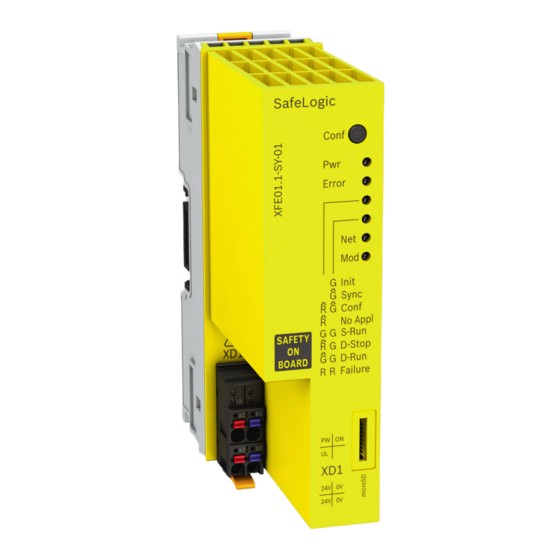
IndraControl XFE01.1-SY-01 Safety Ex- 29/41 tension Module Device description 12 Device description 24 V voltage supply Attached bus base module ① ③ ② SD slot with SD card Fig. 12-1: Safety extension module IndraControl XFE01.1-SY-01 R911376654_Edition 04 Bosch Rexroth AG... -
Page 36: Sd Card
LED is permanently switched on at runtime, integrated self-tests determined a "fatal error" (e.g. hardware error). The Safety extension module IndraControl XFE01.1-SY-01 is then probably defective and has to be replaced. Contact the Bosch Rexroth Service Tab. 12-1: LEDs to display operational readiness LED "Run" LED "Failure"... - Page 37 Red, flashing Green, flashing Firmware update is running Green, flashing Red, flashing Special operating mode for the Bosch Rexroth service em- ployees Tab. 12-2: Operating state display of the Safety extension module IndraControl XFE01.1- SY-01 Color and status Description...
-
Page 38: Led On Xd1 Plug
For further information in the event of repair, please contact the Bosch Rexroth Service. 14 Maintenance Only the maintenance works at the device listed in this chapter are permitted. For further information in the event of repair, please contact the Bosch Rexroth Service. Bosch Rexroth AG R911376654_Edition 04... -
Page 39: Cleaning Notes
● Damage or rupture ● Replace the extension card IndraControl XFE01.1-SY-01 immediately if damaged. In case of damages, please contact the Bosch Rexroth Service. 14.3 Replacing SD card NOTICE Unintended exchange of the SD card can dam- age the Safety extension module IndraControl XFE01.1-SY-01... -
Page 40: Ordering Information
Profibus Slave ..........= 11 Safety Safe Logic to SIL3 ..........= 01 Note: 1) Function type "SY" only available with function Safety "01" Fig. 15-1: Type code of the Safety extension module IndraControl XFE01.1-SY-01 Bosch Rexroth AG R911376654_Edition 04... -
Page 41: Accessories And Spare Parts
You can contact us 24/7. Service Germany Our technology-oriented Competence Center in Lohr, Germany, is responsible for all your service-related queries for electric drive and controls. Contact the Service Hotline and Service Helpdesk under: R911376654_Edition 04 Bosch Rexroth AG... - Page 42 Detailed description of malfunction and circumstances ● Type plate specifications of the affected products, in particular type codes ● and serial numbers Your contact data (phone and fax number as well as your e-mail address) ● Bosch Rexroth AG R911376654_Edition 04...
-
Page 43: Index
End clamps........8 PFH..........12 Error causes........32 Potential equalization....26 Error display......... 30 Power supply unit, external..24 Product identification....3, 4 Product phases....... 1 Pushbutton Conf......30 Feedback........3 Functional earth......26 Qualifications........2 R911376654_Edition 04 Bosch Rexroth AG... - Page 44 Technical data....... 12 Troubleshooting......32 TÜV certificate......15 Type code........34 Type plate........3, 4 UL/CSA certified......16 Use, intended........6 Voltage jumper......26 Voltage supply......12, 24 Warnings......... 4 Weight........... 13 XD1, LED........32 Bosch Rexroth AG R911376654_Edition 04...
- Page 45 IndraControl XFE01.1-SY-01 Safety Ex- 39/41 tension Module R911376654_Edition 04 Bosch Rexroth AG...
- Page 46 40/41 IndraControl XFE01.1-SY-01 Safety Ex- tension Module Bosch Rexroth AG R911376654_Edition 04...
- Page 47 IndraControl XFE01.1-SY-01 Safety Ex- 41/41 tension Module Notes...
- Page 48 Bosch Rexroth AG P.O. Box 13 57 97803 Lohr a.Main, Germany Bgm.-Dr.-Nebel-Str. 2 97816 Lohr a.Main, Germany Phone +49 9352 18 0 Fax +49 9352 18 8400 www.boschrexroth.com/electrics *R911376654* R911376654 DOK-CONTRL -SL**SY*XFE*-IT04-EN-P...
Need help?
Do you have a question about the Rexroth IndraControl XFE01.1-SY-01 and is the answer not in the manual?
Questions and answers