Bosch VIP X1 XF Installation And Operating Manual
Hide thumbs
Also See for VIP X1 XF:
- Installation and operating manual (132 pages) ,
- Quick installation manual (19 pages) ,
- Installation manual (2 pages)
Table of Contents
Advertisement
Advertisement
Table of Contents

Related Manuals for Bosch VIP X1 XF


Summary of Contents for Bosch VIP X1 XF
- Page 1 VIP X1 XF VIPX1XF Installation and Operating Manual...
-
Page 3: Table Of Contents
VIP X1 XF Table of Contents | en Table of Contents Preface About this Manual Conventions in this Manual Intended Use EU Directives Rating Plate Safety Information Electric Shock Hazard Installation and Operation Maintenance and Repair Product Description Scope of Delivery... - Page 4 | Table of Contents VIP X1 XF 5.20 Advanced Mode: Encoder Streams 5.21 Advanced Mode: Audio 5.22 Advanced Mode: Storage Management 5.23 Advanced Mode: Recording Profiles 5.24 Advanced Mode: Retention Time 5.25 Advanced Mode: Recording Scheduler 5.26 Advanced Mode: Recording Status 5.27...
-
Page 5: Vip X1 Xf Table Of Contents | En
VIP X1 XF Table of Contents | en LEDs Processor Load Network Connection Serial Interface Terminal Block Communication with Terminal Program 8.10 Copyrights Specifications Unit Protocols/Standards Glossary Index Bosch Sicherheitssysteme GmbH Installation and Operating Manual DOC | V4.1 | 2010.02... -
Page 6: Preface
Intended Use The VIP X1 XF network video server transfers video, audio and control signals over data networks (Ethernet LAN, Internet). There are various memory options for recording the images captured by the connected camera. The unit is intended for use with CCTV systems. -
Page 7: Eu Directives
VIP X1 XF Preface | en EU Directives The VIP X1 XF network video server complies with the requirements of EU Directives 89/336 (Electromagnetic Compatibility) and 73/23, amended by 93/68 (Low Voltage Directive). Rating Plate For exact identification, the model name and serial number are inscribed on the bottom of the housing. -
Page 8: Safety Information
Maintenance and Repair – Never open the housing of the VIP X1 XF. The unit does not contain any user-serviceable parts. – Never open the housing of the power supply unit. The power supply unit does not contain any user-serviceable parts. -
Page 9: Product Description
Adobe Acrobat Reader NOTICE! Check that the delivery is complete and in perfect condition. Arrange for the unit to be checked by Bosch Security Systems if you find any damage. Bosch Sicherheitssysteme GmbH Installation and Operating Manual DOC | V4.1 | 2010.02... -
Page 10: System Requirements
– Microsoft Internet Explorer (version 7.0 or higher) – Receiver software, for example VIDOS (version 4.01 or higher) or Bosch Video Management System (version 2.2 or higher) – H.264 compatible hardware decoder from Bosch Security Systems (for example VIP XD) as a receiver and connected video monitor –... -
Page 11: Overview Of Functions
Two units, for example a VIP X1 XF as a sender and a VIP XD as a receiver, can create a standalone system for data transfer without a PC. Video images from a single sender can be received simultaneously on multiple receivers. - Page 12 Video Content Analysis and Tamper Detection The VIP X1 XF offers a wide range of configuration options for alarm signaling in the event of tampering with the connected camera. An algorithm for detecting movement in the video image is also part of the scope of delivery and can optionally be extended to include special video analysis algorithms.
- Page 13 VIP X1 XF Product Description | en Summary The VIP X1 XF provides the following main functions: – Video and data transmission over IP data networks – Dual Streaming function for the encoder for simultaneous encoding with two individually definable profiles –...
-
Page 14: Connections, Controls And Displays
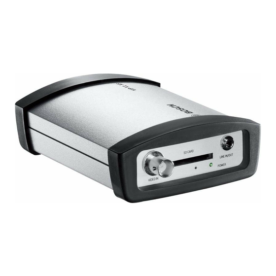
| Product Description VIP X1 XF Connections, Controls and Displays VIDEO IN video input BNC socket for connecting the video source SD CARD slot for an SD card POWER LED lights up green when ready for operation Factory reset button... -
Page 15: Installation
The ambient temperature must be between 0 and +50 °C (+32 and +122 °F). The relative humidity must not exceed 95%. The VIP X1 XF generates heat during operation, so you should ensure that there is adequate ventilation and enough clearance between the unit and heat-sensitive objects or equipment. -
Page 16: Mounting
| Installation VIP X1 XF Mounting You can secure the VIP X1 XF to walls, below ceilings or any other load-bearing locations using the wall-mounting panel, in either a vertical or a horizontal position. CAUTION! The mounting location must be able to reliably hold the unit. The load-bearing capacity must be adequate for four times the weight of the unit. -
Page 17: Connections
Lower ring Ground Connect an audio source with line level to the LINE IN/OUT socket of the VIP X1 XF with a 3.5 mm stereo plug. Network You can connect the VIP X1 XF to a 10/100 Base-T network using a standard UTP category 5 cable with RJ45 plugs. - Page 18 | Installation VIP X1 XF Data Interface The bidirectional data interface is used to control units connected to the VIP X1 XF, such as a dome camera with a motorized lens. The connection supports the RS-232, RS-422 and RS-485 transmission standards.
-
Page 19: Power On/Power Off
The VIP X1 XF does not have a power switch. Power is supplied via a separate unit. Connect the VIP X1 XF to the power supply unit and plug this into the mains. The unit is now ready for use. The VIP X1 XF does not come supplied with a power supply unit. - Page 20 You can start the configuration if a VIP X1 XF is shown in the list in the left section of the window. To do this, right-click the entry for the unit.
-
Page 21: Configuration Using A Web Browser
Configuration Using a Web Browser Connecting The integrated HTTP server in the VIP X1 XF provides you with the option to configure the unit over the network with a Web browser. This option is an alternative to configuration using the Configuration Manager program and is considerably richer in function and more convenient than configuration using the terminal program. - Page 22 VIP X1 XF Establishing the Connection Before you can operate the VIP X1 XF within your network, it must have a valid IP address for your network and a compatible subnet mask. The following default address is preset at the factory: 192.168.0.1 Start the Web browser.
-
Page 23: Configuration Menu
All settings are backed up in the VIP X1 XF memory so they are not lost even if the power fails. The exception is the time settings, which are lost after 72 hours without power if no central time server is selected (see Section 5.4 Basic Mode: Date/Time, page 27). - Page 24 | Configuration Using a Web Browser VIP X1 XF Starting Configuration Click the SETTINGS link in the upper section of the window. The Web browser opens a new page with the configuration menu. Navigation Click one of the menu items in the left window margin. The corresponding submenu is displayed.
-
Page 25: Basic Mode: Device Access
Basic Mode: Device Access Device name You can give the VIP X1 XF a name to make it easier to identify. The name makes the task of administering multiple units in larger video monitoring systems easier, for example using the VIDOS or Bosch Video Management System programs. - Page 26 VIP X1 XF Password A VIP X1 XF is generally protected by a password to prevent unauthorized access to the unit. You can use different authorization levels to limit access. The VIP X1 XF operates with three authorization levels: service, user and live.
-
Page 27: Basic Mode: Date/Time
Click the Sync to PC button to copy your computer's system time to the VIP X1 XF. Time server IP address The VIP X1 XF can receive the time signal from a time server using various time server protocols, and then use it to set the internal clock. -
Page 28: Basic Mode: Network
MAC address, and must be appropriately set up so that, once an IP address is assigned, it is retained each time the system is rebooted. IP address Enter the desired IP address for the VIP X1 XF in this field. The IP address must be valid for the network. Subnet mask Enter the appropriate subnet mask for the selected IP address here. -
Page 29: Basic Mode: Encoder Profile
VIP X1 XF Configuration Using a Web Browser | en Basic Mode: Encoder Profile Default profile You can select a profile for encoding the video signal. You can use this to adapt the video data transmission to the operating environment (for example network structure, bandwidth, data load). -
Page 30: Basic Mode: Audio
| Configuration Using a Web Browser VIP X1 XF Basic Mode: Audio You can set the gain of the audio signals to suit your specific requirements. Your changes are effective immediately. If you connect via Web browser, you must activate the audio transmission on the LIVEPAGE Functions page (see Section 5.15 Advanced Mode: LIVEPAGE Functions, page 40). -
Page 31: Basic Mode: Recording
Configuration Using a Web Browser | en Basic Mode: Recording You can record the images from the camera connected to the VIP X1 XF on the local SD card or on an appropriately configured iSCSI system. SD cards (see Section SD Slot, page 17) are the ideal solution for shorter storage times. -
Page 32: Advanced Mode: Identification
Device name You can give the VIP X1 XF a name to make it easier to identify. The name makes the task of administering multiple units in larger video monitoring systems easier, for example using the VIDOS or Bosch Video Management System programs. - Page 33 Initiator extension You can attach your own text to the initiator name of the VIP X1 XF to make the unit easier to identify in large iSCSI systems. This text is added to the initiator name, separated from it by a full stop.
-
Page 34: Advanced Mode: Password
VIP X1 XF 5.11 Advanced Mode: Password A VIP X1 XF is generally protected by a password to prevent unauthorized access to the unit. You can use different authorization levels to limit access. NOTICE! Proper password protection is only guaranteed when all higher authorization levels are also protected with a password. -
Page 35: Advanced Mode: Date/Time
– it is added automatically. Enter the current time or click the Sync to PC button to copy your computer's system time to the VIP X1 XF. Device time zone Select the time zone in which your system is located. - Page 36 Now click the OK button to save and activate the table. Time server IP address The VIP X1 XF can receive the time signal from a time server using various time server protocols, and then use it to set the internal clock. The unit polls the time signal automatically once every minute.
-
Page 37: Advanced Mode: Display Stamping
VIP X1 XF Configuration Using a Web Browser | en 5.13 Advanced Mode: Display Stamping Various overlays or "stamps" in the video image provide important supplementary information. These overlays can be enabled individually and are arranged on the image in a clear manner. - Page 38 | Configuration Using a Web Browser VIP X1 XF Alarm message Enter the message to be displayed in the image in the event of an alarm. The maximum text length is 31 characters. Video watermarking Choose On if you wish the transmitted video images to be "watermarked". After activation, all images are marked with a green W.
-
Page 39: Advanced Mode: Appearance
Internet/Intranet). When accessing via the Internet/Intranet, ensure that a connection is always available to display the image. The image file is not stored in the VIP X1 XF. Website language Select the language for the user interface here. -
Page 40: Advanced Mode: Livepage Functions
Bilinx control Next to the field for view control at the top left of the LIVEPAGE, an additional field is displayed for the special Bosch Security Systems Bilinx control. Lease time (s) The lease time in seconds determines the time beyond which a different user is authorized to control the camera after no further control signals are received from the current user. - Page 41 VIP X1 XF Configuration Using a Web Browser | en Show relay outputs Relay outputs are shown next to the video image as icons, along with their assigned names. If the relay is switched, the icon changes color. Show VCA trajectories The trajectories (motion lines of objects) from the video content analysis are displayed in the live video image if a corresponding analysis type is activated (see Section 5.31 Advanced Mode:...
-
Page 42: Advanced Mode: Logging
| Configuration Using a Web Browser VIP X1 XF 5.16 Advanced Mode: Logging Save event log Check this option to save event messages in a text file on your local computer. You can then view, edit and print this file with any text editor or the standard Office software. -
Page 43: Advanced Mode: Video Input
5.17 Advanced Mode: Video Input You can activate the 75 Ohm terminating resistance for the video input of the VIP X1 XF. The terminating resistance must be deactivated for the video signal to be looped through. Every video input is closed at the time of delivery. -
Page 44: Advanced Mode: Picture Settings
| Configuration Using a Web Browser VIP X1 XF 5.18 Advanced Mode: Picture Settings You can set the video image of the camera to suit your requirements. The current video image is displayed in the small window next to the slide controls as confirmation. Your changes are effective immediately. -
Page 45: Advanced Mode: Encoder Profile
VIP X1 XF Configuration Using a Web Browser | en 5.19 Advanced Mode: Encoder Profile You can change the names and individual parameter values for the encoder profiles. You can use this to adapt the video data transmission to the operating environment (for example network structure, bandwidth, data load). - Page 46 Encoder Streams page in the lists of selectable profiles. Target data rate You can limit the data rate for the VIP X1 XF to optimize utilization of the bandwidth in your network. The target data rate should be set according to the desired picture quality for typical scenes with no excessive motion.
- Page 47 VIP X1 XF Configuration Using a Web Browser | en Default Click Default to return the profile to the factory default values. Bosch Sicherheitssysteme GmbH Installation and Operating Manual DOC | V4.1 | 2010.02...
-
Page 48: Advanced Mode: Encoder Streams
5.20 Advanced Mode: Encoder Streams The VIP X1 XF simultaneously generates two data streams (Dual Streaming); you can select the relevant property for these here and connect them to an encoder profile, for example one for transmissions to the Internet and one for LAN connections. - Page 49 VIP X1 XF Configuration Using a Web Browser | en Default profile Select the required encoder profile here. The properties of the profiles are defined on the Encoder Profile page (see Section 5.19 Advanced Mode: Encoder Profile, page 45). JPEG stream You can set up the separate JPEG stream in this area.
-
Page 50: Advanced Mode: Audio
| Configuration Using a Web Browser VIP X1 XF 5.21 Advanced Mode: Audio You can set the gain of the audio signals to suit your specific requirements. The current video image is shown in the small window next to the slide controls to help you check the audio source and improve assignments. -
Page 51: Advanced Mode: Storage Management
5.22 Advanced Mode: Storage Management You can record the images from the camera connected to the VIP X1 XF on the local SD card or on an appropriately configured iSCSI system. SD cards (see Section SD Slot, page 17) are the ideal solution for shorter storage times and temporary recordings, for example alarm recordings or local buffering in the event of network interruptions. - Page 52 Each storage medium can only be associated with one user. If a storage medium is already being used by another user, you can decouple the user and connect the drive with the VIP X1 XF. Before decoupling, make absolutely sure that the previous user no longer needs the storage medium.
- Page 53 VIP X1 XF Configuration Using a Web Browser | en CAUTION! If older recordings are not allowed to be overwritten when the available memory capacity has been used, the recording in question will be stopped. You can specify limitations for overwriting old recordings by configuring the retention time (see Section 5.24 Advanced Mode:...
-
Page 54: Advanced Mode: Recording Profiles
| Configuration Using a Web Browser VIP X1 XF 5.23 Advanced Mode: Recording Profiles You can define up to ten different recording profiles. You will then use these recording profiles in the recording scheduler, where they are linked with the individual days and times (see Section 5.25 Advanced Mode: Recording Scheduler, page 57). - Page 55 VIP X1 XF Configuration Using a Web Browser | en Stream profile settings You can select the profile setting that is to be used for each data stream in the event of recordings. This selection is independent of the selection for live data stream transmission (see Section 5.20 Advanced Mode: Encoder Streams, page 48).
-
Page 56: Advanced Mode: Retention Time
Section 5.35 Advanced Mode: Alarm Inputs, page 75). The numbering of the checkboxes for the alarm inputs corresponds to the labeling of the alarm inputs on the VIP X1 XF. The motion alarm is configured and activated on the VCA page (see Section 5.28 Advanced Mode: VCA, page 62 onwards). -
Page 57: Advanced Mode: Recording Scheduler
VIP X1 XF Configuration Using a Web Browser | en 5.25 Advanced Mode: Recording Scheduler The recording scheduler allows you to link the created recording profiles with the days and times at which the camera's images are to be recorded in the event of an alarm. - Page 58 Click the Stop button to deactivate the recording scheduler. Running recordings are interrupted and the configuration can be changed. Recording status The graphic indicates the recording activity of the VIP X1 XF. You will see an animated graphic while recording is taking place. DOC | V4.1 | 2010.02...
-
Page 59: Advanced Mode: Recording Status
Advanced Mode: Alarm Connections You can select how the VIP X1 XF responds to an alarm. In the event of an alarm, the unit can automatically connect to a pre-defined IP address. You can enter up to ten IP addresses to which the VIP X1 XF will connect in sequence in the event of an alarm, until a connection is made. - Page 60 NOTICE! If you enter the destination IP address 0.0.0.0 for destination 10, the VIP X1 XF will no longer use this address for the tenth attempt at automatic connection in the event of an alarm. The parameter is then used only to save the general password.
- Page 61 NOTICE! Please note that the SSL encryption must be activated and configured at both ends of a connection. This requires the appropriate certificates to be uploaded onto the VIP X1 XF (see Section SSL certificate, page 87). You can activate and configure encryption of the media data (video, audio and metadata) on the Encryption page (see Section 5.42 Advanced Mode: Encryption, page 85).
-
Page 62: Advanced Mode: Vca
5.28 Advanced Mode: VCA The VIP X1 XF contains an integrated video content analysis (VCA), which can detect and analyze changes in the signal using image processing algorithms. Such changes can be due to movements in the camera's field of view. -
Page 63: Advanced Mode: Vca Profiles
VIP X1 XF Configuration Using a Web Browser | en 5.29 Advanced Mode: VCA Profiles You can configure two profiles with different VCA configurations. You can save profiles on your computer's hard drive and load saved profiles from there. This can be useful if you want to test a number of different configurations. - Page 64 NOTICE! Additional analysis algorithms with comprehensive functions, such as IVMD and IVA, are available from Bosch Security Systems. If you select one of these algorithms, you can set the corresponding parameters here directly. You can find information on this in the relevant documents on the product CD supplied.
- Page 65 VIP X1 XF Configuration Using a Web Browser | en Motion detector (MOTION+ only) For the detector to function, the following conditions must be met: – Analysis must be activated. – At least one sensor field must be activated. –...
- Page 66 | Configuration Using a Web Browser VIP X1 XF NOTICE! The options for tamper detection can only be set for fixed cameras. Dome cameras or other motorized cameras cannot be protected in this manner as the movement of the camera itself causes changes in the video image that are too great.
- Page 67 VIP X1 XF Configuration Using a Web Browser | en Reference check You can save a reference image that is continuously compared with the current video image. If the current video image in the marked areas differs from the reference image, an alarm is triggered.
-
Page 68: Advanced Mode: Vca Scheduled
| Configuration Using a Web Browser VIP X1 XF 5.30 Advanced Mode: VCA Scheduled This configuration allows you to link the created VCA profile with the days and times at which the video content analysis is to be active. - Page 69 VIP X1 XF Configuration Using a Web Browser | en Holidays You can define holidays on which a profile should be active that are different to the standard weekly schedule. This allows you to apply a schedule for Sundays to other days with dates that fall on varying weekdays.
-
Page 70: Advanced Mode: Vca Event Triggered
| Configuration Using a Web Browser VIP X1 XF 5.31 Advanced Mode: VCA Event triggered This configuration allows you stipulate that the video content analysis is only to be activated when triggered by an event. As long as no trigger is activated, the Silent MOTION+ configuration in which metadata is created is active;... -
Page 71: Advanced Mode: Audio Alarm
5.32 Advanced Mode: Audio Alarm The VIP X1 XF can create alarms on the basis of audio signals. You can configure signal strengths and frequency ranges in such a way that false alarms, for example due to machine noise or background noise, are avoided. -
Page 72: Advanced Mode: Alarm E-Mail
VIP X1 XF Name The name makes it easier to identify the alarm in extensive video monitoring systems, for example with the VIDOS and Bosch Video Management System programs. Enter a unique and clear name here. CAUTION! Do not use any special characters, for example &, in the name. - Page 73 VIP X1 XF Configuration Using a Web Browser | en Mail server IP address Enter the IP address of a mail server that operates on the SMTP standard (Simple Mail Transfer Protocol). Outgoing e-mails are sent to the mail server via the address you entered.
-
Page 74: Advanced Mode: Alarm Task Editor
| Configuration Using a Web Browser VIP X1 XF 5.34 Advanced Mode: Alarm Task Editor CAUTION! Editing scripts on this page overwrites all settings and entries on the other alarm pages. This procedure cannot be reversed. In order to edit this page, you must have programming knowledge and be familiar with the information in the Alarm Task Script Language document. -
Page 75: Advanced Mode: Alarm Inputs
Configuration Using a Web Browser | en 5.35 Advanced Mode: Alarm Inputs You can configure the alarm inputs of the VIP X1 XF. Alarm input Select N.O. if the alarm is to be triggered when the contact closes. Select N.C. if the alarm is to be triggered when the contact opens. - Page 76 | Configuration Using a Web Browser VIP X1 XF For example, if you want an alarm-activated lamp to stay on after the alarm ends, select Bistable. If you wish an alarm-activated siren to sound for ten seconds, for example, select 10 s.
-
Page 77: Advanced Mode: Com1
NOTICE! If the VIP X1 XF is working in multicast mode (see Section 5.40 Advanced Mode: Multicasting, page 83), the first remote location to establish a video connection to the unit is also assigned the transparent data connection. However, after about 15 seconds of inactivity the data connection is automatically terminated and another remote location can exchange transparent data with the unit. -
Page 78: Advanced Mode: Network
5.38 Advanced Mode: Network The settings on this page are used to integrate the VIP X1 XF into an existing network. Some changes only take effect after the unit is rebooted. In this case, the Set button changes to Set and Reboot. - Page 79 MAC address, and must be appropriately set up so that, once an IP address is assigned, it is retained each time the system is rebooted. IP address Enter the desired IP address for the VIP X1 XF in this field. The IP address must be valid for the network. Subnet mask Enter the appropriate subnet mask for the selected IP address here.
- Page 80 You can specify a higher MSS value for a connection to the iSCSI system than for the other data traffic via the network. The potential value depends on the network structure. A higher value is only useful if the iSCSI system is located in the same subnet as the VIP X1 XF. Enable DynDNS DynDNS.org is a DNS hosting service that stores IP addresses in a database ready for use.
- Page 81 Only use this function when necessary and no more than once a day, to avoid the possibility of being blocked by the service provider. To transfer the IP address of the VIP X1 XF, click the Register button. Status The status of the DynDNS function is displayed here for information purposes.
-
Page 82: Advanced Mode: Advanced
Some changes only take effect after the unit is rebooted. In this case, the Set button changes to Set and Reboot. Make the desired changes. Click the Set and Reboot button. The VIP X1 XF is rebooted and the changed settings are activated. SNMP The VIP X1 XF supports the SNMP V2 (Simple Network Management Protocol) for managing and monitoring network components, and can send SNMP messages (traps) to IP addresses. -
Page 83: Advanced Mode: Multicasting
The RADIUS server must also contain the corresponding data. To configure the unit, you must connect the VIP X1 XF directly to a computer using a network cable. This is because communication via the network is not enabled until the Identity and Password parameters have been set and successfully authenticated. -
Page 84: Advanced Mode: Jpeg Posting
With the setting 0.0.0.0 the encoder for the relevant stream operates in multi-unicast mode (copying of data streams in the unit). The VIP X1 XF supports multi-unicast connections for up to five simultaneously connected receivers. -
Page 85: Advanced Mode: Encryption
VIP X1 XF Configuration Using a Web Browser | en File name You can select how file names will be created for the individual images that are transmitted. – Overwrite The same file name is always used and any existing file will be overwritten with the current file. -
Page 86: Advanced Mode: Maintenance
Advanced Mode: Maintenance Firmware The VIP X1 XF is designed in such a way that its functions and parameters can be updated with firmware. To do this, transfer the current firmware package to the unit via the selected network. It will then be automatically installed there. - Page 87 You can upload the SSL certificate, comprising one or multiple files, onto the VIP X1 XF. If you wish to upload multiple files onto the VIP X1 XF, you must select them consecutively. NOTICE! The certificate must be created in the format *.pem so that it can be accepted by the unit.
-
Page 88: Advanced Mode: Licenses
| Configuration Using a Web Browser VIP X1 XF 5.44 Advanced Mode: Licenses You can enter the activation key to release additional functions or software modules. NOTICE! The activation key cannot be deactivated again and is not transferable to other units. -
Page 89: Function Test
The VIP X1 XF offers a variety of configuration options. You should therefore check that it is functioning correctly after installation and configuration. The function test is the only way to ensure that the VIP X1 XF operates as expected in the event of an alarm. -
Page 90: Operation
Operation Operation with Microsoft Internet Explorer A computer with Microsoft Internet Explorer (version 7.0 or higher) can receive live images from the VIP X1 XF, control cameras or other peripherals and replay stored video sequences. System Requirements – Computer with Windows XP or Windows Vista operating system –... - Page 91 Operation | en Establishing the Connection Before you can operate the VIP X1 XF within your network, it must have a valid IP address for your network and a compatible subnet mask. The following default address is preset at the factory: 192.168.0.1 Start the Web browser.
-
Page 92: The Livepage
If you do not connect, the unit may have reached its maximum number of connections. Depending on the unit and network configuration, each VIP X1 XF can have up to 25 Web browser connections or up to 50 connections via VIDOS or Bosch Video Management System. - Page 93 (see Section 5.15 Advanced Mode: LIVEPAGE Functions, page 40). Triggering Relay You can switch connected units using the relays in the VIP X1 XF (for example lights or door openers). ...
- Page 94 VIP X1 XF. Audio signals can only be sent to the VIP X1 XF by the user who connects to the unit first. On the LIVEPAGE, click anywhere next to the video image to remove the focus from the ActiveX.
-
Page 95: Saving Snapshots
Click the icon to start recording. The storage location depends on the configuration of the VIP X1 XF (see Section Path for JPEG and video files, page 41). A red dot in the icon indicates that recording is in progress. -
Page 96: The Recordings Page
| Operation VIP X1 XF The RECORDINGS Page The RECORDINGS page for playing back recorded video sequences can be accessed from the LIVEPAGE and from the SETTINGS menu. The RECORDINGS link is only visible if a storage medium has been selected (see Section 5.22 Advanced Mode: Storage Management, page 51). - Page 97 VIP X1 XF Operation | en You can change the time interval by clicking the zoom keys (magnifying glass icons). The display can span a range from two months to a few seconds. Drag the green arrow to the point in time at which playback should begin. The date and time display below the bar provides orientation to the second.
-
Page 98: Installing Player
| Operation VIP X1 XF Installing Player You can play back saved video sequences using the Player program from Bosch Security Systems, which can be found on the product CD supplied (see Section 3.1 Scope of Delivery, page 9). -
Page 99: Hardware Connections Between Video Servers
Hardware Connections Between Video Servers A VIP X1 XF with a camera connected to it can be used as a sender and a compatible hardware decoder (such as the VIP XD) with a connected monitor as a receiver using an Ethernet network connection. - Page 100 100 en | Operation VIP X1 XF Connecting with a Terminal Program Various requirements must be met in order to operate with a terminal program (see Section 8.9 Communication with Terminal Program, page 111). Start the terminal program and enter the command 4 in the main menu to switch to the Rcp+ menu.
-
Page 101: Operation Using Software Decoders
The VIP X1 XF video server is also designed for use with the DiBos 8 digital recorder. DiBos 8 records up to 32 video and audio streams and is available as IP software or hybrid DVR with additional analog camera and audio inputs. -
Page 102: Maintenance And Upgrades
POWER LED flashes red (see Section 3.4 Connections, Controls and Displays, page 14). All settings will revert to their defaults. Change the IP address of the VIP X1 XF if necessary. Configure the unit to meet your requirements. DOC | V4.1 | 2010.02... -
Page 103: Repairs
Transfer and Disposal The VIP X1 XF should only be passed on together with this installation and operating manual. Your Bosch product is designed and manufactured with high-quality materials and components which can be recycled and reused. -
Page 104: Appendix
If you are unable to resolve a malfunction, please contact your supplier or systems integrator, or go directly to Bosch Security Systems Customer Service. You can view a range of information about your unit version on the System Overview page (see Section 5.45 Advanced Mode: System Overview, page 88). -
Page 105: General Malfunctions
VIP X1 XF Appendix | en 105 General Malfunctions Malfunction Possible causes Recommended solution No connection between Incorrect cable connections. Check all cables, plugs, the unit and terminal contacts, terminals and program. connections. The computer's serial interface Check the other serial interface. - Page 106 106 en | Appendix VIP X1 XF Malfunction Possible causes Recommended solution The unit does not report Alarm source is not selected. Select possible alarm sources on an alarm. the Alarm Inputs configuration page. No alarm response specified. Specify the desired alarm...
-
Page 107: Malfunctions With Iscsi Connections
VIP X1 XF Appendix | en 107 Malfunctions with iSCSI Connections Malfunction Possible causes Recommended solution After connecting to the Incorrect LUN mapping during Check the iSCSI system iSCSI destination, no iSCSI system configuration. configuration and reconnect. LUNs are displayed. -
Page 108: Leds
108 en | Appendix VIP X1 XF LEDs The VIP X1 XF network video server has LEDs on its front and rear panels that show the operating status and can give indications of possible malfunctions: POWER LED Does not light up: VIP X1 XF is switched off. -
Page 109: Processor Load
Appendix | en 109 Processor Load If the VIP X1 XF is accessed via the Web browser, you will see the processor load indicator in the top left of the window next to the manufacturer's logo. You can obtain additional information to help you when troubleshooting or fine tuning the unit. -
Page 110: Terminal Block
110 en | Appendix VIP X1 XF Terminal Block The terminal block has several contacts for: – 2 alarm inputs – 2 relay outputs – Serial data transmission Pin Assignment The pin assignment of the serial interface depends on the interface mode used (see Section 5.37 Advanced Mode: COM1, page 77). -
Page 111: Communication With Terminal Program
Communication with Terminal Program Data Terminal If a VIP X1 XF cannot be found in the network or the connection to the network is interrupted, you can connect a data terminal to the VIP X1 XF for initial setup and setting of important parameters. - Page 112 VIP X1 XF Assigning an IP Address Before you can operate a VIP X1 XF in your network you must first assign it an IP address that is valid for your network. The following default address is preset at the factory: 192.168.0.1 Start a terminal program such as HyperTerminal.
-
Page 113: Copyrights
VIP X1 XF Appendix | en 113 8.10 Copyrights The firmware 4.1 uses the fonts "Adobe-Helvetica-Bold-R-Normal--24-240-75-75-P-138- ISO10646-1" and "Adobe-Helvetica-Bold-R-Normal--12-120-75-75-P-70-ISO10646-1" under the following copyright: Copyright 1984-1989, 1994 Adobe Systems Incorporated. Copyright 1988, 1994 Digital Equipment Corporation. Permission to use, copy, modify, distribute and sell this software and its documentation for... -
Page 114: Specifications
114 en | Specifications VIP X1 XF Specifications Unit Operating voltage 9 to 30 V DC, power supply via external unit Power consumption Approx. 5 VA LAN interfaces 1 × Ethernet 10/100 Base-T, automatic adjustment, half/full duplex, RJ45 Data interfaces 1 ×... -
Page 115: Protocols/Standards
VIP X1 XF Specifications | en 115 Protocols/Standards Video standards PAL, NTSC Video coding protocols H.264 MP (Main Profile), H.264 BP+, M-JPEG, JPEG Video data rate 9.6 kbps to 6 Mbps Image resolutions (PAL/NTSC) 704 × 576/480 pixels (4CIF) 352 × 288/240 pixels (CIF) Total delay 120 ms (PAL/NTSC, H.264, no network delay) -
Page 116: Glossary
Unit of measure for the speed of data transmission Bits per second, the actual data rate BVIP Bosch Video over IP unit CompactFlash; interface standard, for digital storage media amongst other things. Used in computers in the form of CF cards, digital cameras and Personal Digital Assistants (PDA). - Page 117 VIP X1 XF Glossary | en 117 H.264 Standard for high-efficiency video compression, based on the predecessors MPEG-1, MPEG-2 and MPEG-4. H.264 typically achieves a coding efficiency around three times as high as MPEG- 2. This means that comparable quality can be achieved at around a third of MPEG-2 data quantity.
- Page 118 118 en | Glossary VIP X1 XF Management Information Base; a collection of information for remote servicing using the SNMP protocol MPEG-2 Improved video/audio compression standard, compression on highest level allows images in studio quality; now established as broadcast standard...
- Page 119 VIP X1 XF Glossary | en 119 Small Form-factor Pluggable; small, standardized module for network connections, designed as a plug connector for high-speed network connections SNIA Storage Networking Industry Association; association of companies for defining the iSCSI standard SNMP Simple Network Management Protocol; a protocol for network management, for managing and...
-
Page 120: Index
120 en | Index VIP X1 XF Index Activating the recording 58 Echo 111 Activation key 88 Electromagnetic compatibility 7 Alarm 14 E-mail 72 Alarm e-mail 72 Encoder load 109 Alarm input 18 Encoding 11 Alarm inputs 75 Encryption protocol 79... - Page 121 VIP X1 XF Index | en 121 Motion detector defaults 62 Reset 14 Motion detector object size 65 Router 84 Motion detector sensitivity 65 MPEG ActiveX 21 Safety 8 MTU value 79 Saturation 44 Multicast address 84 Saving event log 42...
- Page 122 122 en | Index VIP X1 XF Unit date 35 Unit identification 25 Unit name 25 Unit reset 102 Unit time 27 URL 22 User name 26 Value 44 VCR 43 Video content analysis 62 Video input 43 Video sensor 62...
- Page 124 Bosch Sicherheitssysteme GmbH Werner-von-Siemens-Ring 10 85630Grasbrunn Germany www.boschsecurity.com © Bosch Sicherheitssysteme GmbH, 2010...
Need help?
Do you have a question about the VIP X1 XF and is the answer not in the manual?
Questions and answers