Table of Contents
Advertisement
Quick Links
Advertisement
Table of Contents

Related Manuals for Korg X5DR AI2 SYNTHESIS MODULE


Summary of Contents for Korg X5DR AI2 SYNTHESIS MODULE
- Page 1 SYNTHESIS MODULE GENERAL INSTRUMENT Owner’s Manual Synthesis System...
- Page 2 Based on state-of-the-art PCM technology, the AI Synthesis System is technology developed by Korg to capture the true essence of acoustic sound for use in a tone generator. Since its introduction in Korg's 01/W series, X2/X3/X5, and i2/i3 synthesizers, the AI Synthesis System has received unqualified praise from musicians and artists throughout the world.
- Page 3 You can connect the X5DR to a computer through either a MIDI connection using a MIDI interface, or through a direct connection using a serial cable. Using the Korg MIDI Driver will allow you to control data transmission from MIDI OUT independently of the X5DR tone...
-
Page 4: Controls
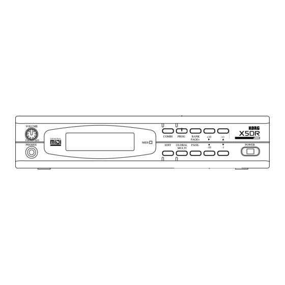
Controls Controls Front Panel [COMBI] button [PROG] button [BANK]/[PAGE+] button, [PAGE–] button [+10]/[¤] button, [–10]/[ˆ] button VOLUME [+1]/[ £] button, [–1]/[ ¥] button VOLUME COMBI PROG BANK PAGE+ MIDI PHONES POWER EDIT GLOBAL PAGE- MULTI MIDI indicator Power switch LCD display [GLOBAL]/[MULTI] button PHONES jack [EDIT] button... - Page 5 Controls 6 [+1]/[ ] button, [–1]/[ ] button In Program Play mode and Combination Play mode, pressing the [+1] and [–1] buttons increment and decrement the Program and Combination numbers in steps of 1. In Program Edit mode, Combination Edit mode, Multi mode, and Global mode, these buttons can be used to increase and decrease the currently-selected parameter value.
-
Page 6: Rear Panel
Rear Panel Rear Panel DC IN MIDI (IN, OUT, THRU) MIDI DC IN 12V TO HOST THRU 700mA OUTPUT L/MONO TO HOST OUTPUT (L/MONO, R) 1 DC IN Connect the AC adapter here. Note: Do not use adapters other than the AC adapter that comes with the X5DR! Otherwise, a malfunction may occur. - Page 7 Controls...
-
Page 8: Table Of Contents
Table of Contents Table of Contents Introduction ........................i Features of the X5DR ..................... i Controls ........................iii Front Panel ........................iii Rear Panel ........................v Table of Contents ......................vii About this manual ....................... xii Start-up Guide Using a Keyboard Connections ........................ -
Page 9: Table Of Contents
Table of Contents Basic Guide 1. X5DR Modes Program Play mode ..................... 21 Playing Programs ....................21 Basic operation in Program Play mode ............. 21 Program Edit Mode ..................... 23 Basic operation in Program Edit mode ............. 23 Combination Play Mode ....................24 Playing Combinations .................. - Page 10 Table of Contents Preparing to Play a Drum Kit ................53 Editing a Drum Kit .................... 53 Creating a Drum Program Using a ROM Drum Kit ......... 56 4. Application Guide General Troubleshooting ..................... 57 Nothing is displayed on the LCD when the power switch is turned on..57 The X5DR does not produce any sound.
- Page 11 Installing the KORG MIDI Driver in MS Windows ..........174 Setting Up the KORG MIDI Driver (Windows) ............176 Installing the KORG MIDI Driver on a Macintosh Computer ......... 177 Setting Up the KORG MIDI Driver for the Macintosh ..........178 MIDI File Translator ....................
-
Page 12: About This Manual
About this manual About this manual This manual consists of the following chapters to enable you to extract information relevant to your environment and applications. Start-up Guide This chapter explains the set-up procedure and basic operation of the X5DR. This chapter is divided into two sections: “Using a Keyboard”... - Page 13 About this manual...
-
Page 14: Start-Up Guide
Start-up Guide Start-up Guide Using a Keyboard Connections To use the headphones, plug the Connecting to a power source headphone cable into the PHONES jack on the front panel. Connect the AC adapter plug Using a Using a to the DC IN connector on the VOLUME Keyboard Keyboard... -
Page 15: Midi Keyboard Settings
Start-up Guide MIDI Keyboard Settings Use the following MIDI keyboard transmit settings before you play the X5DR from a connected keyboard. Refer to the MIDI keyboard manual for detailed settings. • The X5DR is a MIDI tone module that receives MIDI data sent from external MIDI devices (such as a MIDI keyboard, computer, or sequencer) to playback data. -
Page 16: Listening To A Demo Performance
PAGE- MULTI Demo performance Demo Song 1: AROUND THE WORLD By Stephen Kay Demo Song 2: WE’VE GOT DREAMS By KORG Inc. Combination Play mode Operation in Demo mode The X5DR automatically enters Combination Play mode Demo Song 1: AROUND THE WORLD when you turn the power on. -
Page 17: Playing Programs
Start-up Guide Playing Programs The X5DR has two types of sounds: Programs and Combinations. First we will listen to some Programs. Program Play mode Program Play mode enables you to play Programs. Press the [PROG] button to enter Program Play mode. The display shows the Program A00:PipeDreams Bank number, Program number,... -
Page 18: If No Sound Is Produced
Start-up Guide If No Sound is Produced: If no sound is produced from the X5DR when you play the MIDI keyboard, or if you cannot change Programs, check the following items: No sound is produced: Check to see if the Demo songs can be played. If not, check to see if the volume level of the X5DR and the connected powered monitor or stereo amplifier is sufficient. - Page 19 Start-up Guide A09:[KrazyKit] This is a Program for a rhythm part (Drum Program), with a different sound assigned to each key on the keyboard. The A09:[KrazyKit] Program contains not only drum sounds but human voices and various effect sounds. When you play key C3 on the keyboard, the sound does not stop—rather, the sound volume increases.
-
Page 20: Playing Combinations
Start-up Guide Playing Combinations Combinations are another type of sound on the X5DR. We will listen to some Combinations now. A Combination consists of several Programs. You can play different Programs by applying a different key touch on the keyboard, or you can use Combinations to obtain a more complex sound. -
Page 21: Combination Examples
Start-up Guide Combination Examples The X5DR has 100 Combinations (00–99). Play and listen to a variety of Combinations. The following are some examples of the X5DR’s unique Combinations. Take a listen to the following: 12:Wind Orch This orchestra sound combines woodwind, strings, and timpani sounds. With a low key velocity, the woodwind sound is produced, and with a high key velocity, a strings sound is produced. -
Page 22: Using A Computer/Sequencer
Start-up Guide Using a Computer/Sequencer Connections To use the headphones, plug the Connecting the power headphone cable into the PHONES jack on the front panel. Connect the AC adapter plug to the DC IN connector on the VOLUME rear panel, and plug the AC Using a MIDI PHONES... -
Page 23: Connecting A Computer Or Sequencer
IBM PC (compatible): Optional connection kit AG-001 (Cables, Software “KORG MIDI Driver”) Apple Macintosh series: Optional connection kit AG-002 (Cables, Software “KORG MIDI Driver”) You might not be able to use these connections depending on the model of computer or the type of application software you use. -
Page 24: Connection Via Midi
Start-up Guide Connection via MIDI To connect a stand-alone MIDI sequencer or a computer with a MIDI interface to the X5DR, use MIDI cables to connect MIDI OUT of the sequencer or computer (MIDI interface) to MIDI IN on the X5DR. MIDI Keyboard MIDI OUT Computer/Sequencer... -
Page 25: Connecting An Ibm Pc (Compatible) Computer
Set 0D PC I/F CLK of the Global mode to “38.4kBPS” (see page 14). If you use this connection with Windows MME or Windows 3.1, you need to install the Korg MIDI Driver. Refer to page 174 for installation information. -
Page 26: Connecting An Apple Macintosh Computer
Set 0D PC I/F CLK of the Global mode to “31.25kBPS.” (See page 14.) Installing the Korg MIDI Driver allows the X5DR to output data from its internal tone generator separately from MIDI OUT data. This makes it possible to use the X5DR as a MIDI interface for... -
Page 27: Settings Required When A Computer Is Connected
Start-up Guide Settings Required When a Computer is Connected If you have connected the X5DR to the computer using a computer interface cable, set the Computer Select (data transfer rate from/to the computer) and External Out Select (data transmission destination from the X5DR). Setting Computer Select (0D PCI/F CLK in Global Mode) 1 Press the [GLOBAL] button to enter Global mode. -
Page 28: Listening To A Demo Performance
PAGE- MULTI Demo performance Demo Song 1: AROUND THE WORLD By Stephen Kay Demo Song 2: WE’VE GOT DREAMS By KORG Inc. Combination Play mode Operation in Demo mode The X5DR automatically enters Combination Play mode Demo Song 1: AROUND THE WORLD when you turn the power on. -
Page 29: Playing The X5Dr In Multi Mode (Playing Back Gm Scores)
Start-up Guide Playing the X5DR in Multi Mode (Playing Back GM Scores) Multi mode allows you to use the X5DR as a 16-channel multi-timbre (GM) tone generator, controlled from the connected computer, to play ensemble music consisting of multiple instrument parts. This section explains playing the X5DR in Multi mode. What is Multi mode? Multi mode Multi mode allows you to use the X5DR as... -
Page 30: Structure Of Multi Mode
Start-up Guide Structure of Multi Mode Multi mode allows you to use the X5DR as a GM tone generator which conforms to General MIDI System Level 1. When GM ON messages are received or when the power is turned on, the GM settings are automatically selected. -
Page 31: Performance Settings
Start-up Guide Performance settings Parameters on the X5DR, or MIDI data sent from a computer or sequencer, allow you to make performance settings such as volume level and pan of each track. On the X5DR, use the [PAGE+] and [PAGE–] buttons to select a track, then use the [®] and [ ] buttons to select a parameter. -
Page 32: If You Cannot Play The X5Dr
Check to see if the MIDI port for the connected MIDI interface or KORG MIDI Driver port has been selected. The KORG MIDI Driver allows you to use different MIDI ports for the tone generator inside the X5DR and MIDI data transmitted from the MIDI OUT connector. -
Page 33: Loading Preset Data
Start-up Guide Loading Preset Data The X5DR has 200 carefully-selected Programs and Combinations (100 types of each) and four Drum Kits (2 types 2), which are all included as Preset data (Preset a/b). • Preset a was loaded when the X5DR was shipped from the factory. 1 Press the [Global] button to enter Global mode. -
Page 34: Basic Guide
Basic Guide Basic Guide 1. X5DR Modes There are six operating modes on the X5DR for use with different performances, settings, and functions: Program Play, Program Edit, Combination Play, Combination Edit, Multi, and Global. Program Play mode Programs are basic sounds that you can play in Program Play mode. The X5DR contains 236 Programs organized in banks as follows: 100 (A00–99) in RAM (Random Access Memory) where you can store created or edited sounds, and 136 (G01–136) in the built-in preset area. - Page 35 Basic Guide [+1]/[–1] button: Increase/decrease the Program number in steps of 1. Pressing the [BANK] button each time will toggle between Bank A and G. Pressing the [+10]/[–10] button increases/decreases the Program number in steps of 10. COMBI PROG BANK PAGE+ Pressing the [+1]/[–1] button increases/decreases the Program number EDIT...
-
Page 36: Program Edit Mode
Basic Guide Program Edit Mode Program Edit mode allows you to modify Pitch1 MG VDF1 EG VDA1 EG the sound of Programs. The figure shows the structure of a Program. You can create Audio signal Pan A&B Control signal Oscillator1 VDF1 VDA1 your own sound and modify its tonal color... -
Page 37: Combination Play Mode
Basic Guide Combination Play Mode Combinations (a combination of Programs) can use up to eight Timbres. Each Timbre is assigned a Program. You can play Combinations in Combination Play mode. The X5DR contains 100 Combinations (00–99). Key Window Timbre 1 Keyboard range played by each Timbre Timbre 2... -
Page 38: Combination Types
Basic Guide Changing Combinations on the unit [+10]/[–10] button: Increase/decrease the Combination number in steps of 10. [+1]/[–1] button: Increase/decrease the Combination number in steps of 1. Pressing the [+10]/[–10] button increases/decreases the Combination number in steps of 10. COMBI PROG BANK PAGE+... -
Page 39: Combination Edit Mode
Basic Guide VSw (Velocity Switch) Timbres can be set to respond to a specific key velocity (how firmly you strike the keys). For example, you can set Timbres in such a way that a strings sound is produced when you play the keyboard softly, and a brass sound is produced when you play the keyboard hard. -
Page 40: Multi Mode
Basic Guide Multi Mode In Multi mode, you can play the X5DR as a 16-part multi-timbral GM tone generator. In this mode, 16 tracks are available to play Bank A and G Programs. Playing the X5DR in Multi mode In Multi mode, you can use 16 tracks, each of which can be assigned to a different MIDI receive channel. - Page 41 Basic Guide Default settings in Multi mode The following table shows the default settings for Multi mode that are automatically selected when the X5DR power is turned on, or when the X5DR receives a GM ON message (F0 7E 7F 09 01 F7).
-
Page 42: Global Mode
Basic Guide Global Mode In this mode you can make settings that affect the entire X5DR (overall tuning and MIDI-related settings), and assign drum sounds to a Drum kit. Basic operation in Global mode Press the [GLOBAL] button to enter Global mode. COMBI PROG BANK... -
Page 43: Performance Techniques
From the computer There are two ports for a signal sent from the computer: KORG PC I/F MIDI Port and KORG PC I/F Synth Port. The signal at the KORG PC I/F MIDI Port is output from the MIDI OUT connector. -
Page 44: Signal Flow In Various Modes
Basic Guide • The KORG PC I/F MIDI Port and the KORG PC I/F Synth Port are available when you are using the KORG MIDI Driver. (See page 177) If you are not using the KORG MIDI Driver, the signal is output to both ports simultaneously. -
Page 45: Received Midi Data
Basic Guide Multi mode In Multi mode, the X5DR plays back data on each Track’s MIDI receive channel. Sending Program Change and Bank Select messages will change the Program used for the corresponding Track. When you turn on the X5DR power, when the X5DR receives a GM system on message, or when 23A SET TO GM in Multi mode is executed, each Track’s MIDI receive channel is set to the same number as the Track number. -
Page 46: After Touch
Basic Guide After Touch While you play the keyboard, pressing the keys harder will control tonal brightness. The X5DR can receive After Touch message (Channel Pressure). Control Change Sending this message allows you to adjust performance conditions, such as the volume level and pan settings. -
Page 47: Performance Functions
Basic Guide Effect On/Off (CTRL #92/94) These messages switch Effect 1 (CTRL#92) and Effect 2 (CTRL#94) on and off. Data Increment/Decrement (CTRL#96/97) This message increases or decreases values. It is also used to edit the RPN. In particular, you can use it to edit Programs along with Exclusive data. -
Page 48: Effect Dynamic Modulation
Basic Guide Effect Dynamic Modulation Effect Dynamic Modulation is a function that controls the effect level balance and modulation rate. Controlling the effect parameters using the Control Change messages and volume level (VDA EG) allows for real-time effect adjustment during performance. See page 116 for information on adjusting real-time effect parameters. -
Page 49: Editing
The X5DR is not only a tone generator that provides various factory-set sounds, but also a synthesizer that employs Korg’s powerful AI Synthesis, which allows you to create new, original sounds or to edit existing sounds. Take a moment to try out the sound-editing capabilities of the X5DR. -
Page 50: Eg And Mg
Basic Guide Volume: VDA (amplifier) The VDA allows you to adjust volume. The “volume” referenced here is not the volume of the entire performance, but the volume changes within a sound. For example, the volume of the piano sound starts with a high attack level, then drops gradually. The organ sound volume does not change until you release the key, while the violin volume varies depending on performance technique. -
Page 51: Editing Programs
Basic Guide Editing Programs Before Editing The X5DR offers 236 Programs in Bank A and G, and you can store edited programs in Bank A. When you select Program Edit mode, the Program is copied from Bank A or G to the edit buffer. You will edit Program data in the edit buffer. -
Page 52: Checking The Sound While Editing
Basic Guide Writing Programs To store the Program edited in Program Edit mode, you need to use the Program Write function. Follow the procedure below to write the Program in Bank A. 1 Press the [PAGE+] button in Program Edit mode to select 22A PROG WRITE (in Double mode) or 16A PROG WRITE (in Single and Drums mode). -
Page 53: Adjusting The Attack Of Programs
Basic Guide Adjusting the Attack of Programs Let’s use Program A01: X Piano to edit the speed at which the attack part of the sound reaches its peak. Note: If Program A01 is not X Piano, a Program from Preset b may have been loaded. In this case, load the Program from Preset a before editing (page 20). -
Page 54: Adjusting The Decay
Basic Guide Adjusting the Decay The volume level of Program A01: X Piano is gradually decreased even if you continue holding down the key. This decay portion is set by DT (Decay Time) on page 5A VDA1 EG, and BP (Break Point) and ST (Slope Time) on page 5B VDA1 EG. -
Page 55: Adjusting The Release
Basic Guide Adjusting the Release The release part of a sound that you hear after you release the key (Note-off) will be adjusted by the RT (Release Time) parameter on page 5C VDA1 EG. The default release time setting for Program A01: X Piano is set to 36. Change this value and listen to the sound. - Page 56 Basic Guide Level Frequency Cutoff frequency The VDF EG allows you to control brightness. The EGint (EG Intensity) parameter on 3A VDF 1 allows you to determine how much the VDF EG will change brightness. The VDF EG does not affect the sound when the EGint parameter is set to 00.
-
Page 57: Editing A Multisound (Basic Waveform)
Basic Guide Editing a Multisound (Basic Waveform) Multisounds are the basic sound waveform (PCM waveform) used in Programs. The X5DR contains 430 Multisounds, including instrumental sounds such as piano and guitar, rhythm sounds such as drums and percussion, and synth sounds. Changes in Multisounds are obvious in any Program. -
Page 58: Adjusting The Panpot
Basic Guide Adjusting the Panpot You can adjust the panpot setting (the position of the stereo image) when the stereo sound is output through the L/MONO and R connectors. Change the Pan (panpot) parameter on 1C OSC1 and check to see how the position of the stereo image has shifted (see page 81). Pan settings range between A and B, with CNT as the center. -
Page 59: Some Hints For Editing Programs
Basic Guide to layer the Programs in Combinations. If the piano and strings sounds are different Programs, this gives you the flexibility to combine the piano and brass sounds, or the strings and brass sounds, allowing you to make the best use of the Programs. On the other hand, layering two Multisounds in Double mode is most suitable for combining two different sounds to build one Program. -
Page 60: Editing Effects
Basic Guide Editing Effects Now let’s edit the effects, which are a prominent feature of the X5DR. An effects processor allows you to add various effects and acoustic ambience to a sound. You can use effects for Programs, Combinations, and Multis. This section explains the editing of effects in a Program. - Page 61 Basic Guide ceiling, and other objects in the room, and the decay time of the reflections. Utilizing the effect types 1: Hall through 9: Spring allows you to simulate a variety of acoustic ambiences, and you can edit these effects in detail using the parameters provided. Dry sound Level Early reflections...
- Page 62 Basic Guide 6) Exciter The exciter effect (28: Exciter) adds new harmonics to a sound, thus producing a subjective increase in clarity and definition, which helps to make a sound’s individual character stand out. 7) Enhancer The enhancer (29: Enhancer) makes the sound clearer and more defined, giving the sound more presence and bringing it up front in the mix.
-
Page 63: Effects And Sound Level
Basic Guide Effects and Sound Level You can use the effects in Programs, Combinations, and Multi mode setup. However, the effects are set for each sound—that is, the effects are set for each Program. Combinations use the effects that are set for each Combination (and not the effects that are set for the Programs assigned to the Timbres). -
Page 64: Editing Combinations
Basic Guide Editing Combinations This section offers a tutorial for editing Combinations. If you wish to save an edited Combination, you must perform a Combination Write operation.) • If you do not save the edited Combination, the existing Combination will not change. (Refer to page 106 for information on the Combination Write operation.) Layering Multiple Programs You can create a new sound by combining multiple Programs in a Combination. -
Page 65: Adjusting The Volume
Basic Guide Adjusting the Volume You can adjust the volume level of each Timbre using the parameters on pages 1A and 1B LEVEL. The Volume balance among Timbres can affect the sound of the Combination. These are the default settings for each Timbre’s volume level for Combination 58: Moon Stone: 106 for A78: Swell pad;... -
Page 66: Editing A Drum Kit
Basic Guide Editing a Drum Kit A Drum Kit is a set of drum sounds, each of which is assigned to a key on the keyboard. You can play a Drum Kit instead of Multisounds by selecting DRUMS for Programs. The Drum sounds on the X5DR are arranged into 8 Drum Kits in ROM and 2 Drum Kits in RAM. - Page 67 Basic Guide 1 Select A19: [ComboKit] in Program Play mode. • When you edit a Drum Kit in Global mode, the currently-selected Program settings (DRUMS for OSC Mode) are used to produce the sound. Make sure you select a Program that contains a Drum Kit you wish to edit.
- Page 68 Basic Guide Changing Drum Sounds As a default setting, drum sound 018: PicloSnare (the high-pitched sound of a thin-body snare) is selected. Try to select various drum sounds and listen to them. Selecting --: No Assign allows you to set an index that does not produce sound. For this example, select a powerful snare sound 022: Ambi.Snare.
-
Page 69: Creating A Drum Program Using A Rom Drum Kit
Basic Guide set the key to C7. Now you should be able to play the bell sound in a chromatic scale within the highest octave (Note numbers 84–95). The sound may become more interesting if you tune it a little lower and set the decay to –15. You can play the drum sound of index #49 in a chromatic scale. -
Page 70: Application Guide
Basic Guide 4. Application Guide This chapter explains several applications and offers helpful tips on performance, editing, and troubleshooting on the X5DR. See the reference pages for detailed explanations of functions and parameters. General Troubleshooting Nothing is displayed on the LCD when the power switch is turned on. Check that the AC adapter is connected correctly. -
Page 71: You Cannot Change Programs Or Combinations
Basic Guide You cannot change Programs or Combinations. Program Change messages are used to change Programs and Combinations. Make sure that the messages are sent from the transmission device. In Program Play mode: Send Program Change messages on the Global MIDI Channel. If you wish to change the Bank, send a Bank Select message. -
Page 72: The X5Dr Doesn't Transmit Midi Exclusive Messages
Basic Guide Make sure that the settings in Global mode have been made correctly for GM songs. (See page 18.) If you are trying to play back a GM score that uses Bank Select messages, the wrong sound may be produced (that is, a Bank A Program may be selected). In this case, restore the initial GM settings, and set the computer or sequencer so that it will not send Bank Select messages, or set the MIDI filter parameter on the X5DR so that it will not receive Bank Select messages. -
Page 73: Performance Applications
Basic Guide Performance Applications Tuning the X5DR to Other Musical Instruments You should first tune the X5DR if you plan to jam with other musical instruments or play along with music from CDs or tapes. Use page 0A MASTER TUNE in Global mode to tune up. The range of the parameter is –50 (427.47Hz) to +50 (452.89Hz). -
Page 74: Changing The Controller Functions In Combinations
Basic Guide Changing the Controller Functions in Combinations You may occasionally want to use different settings for a controller to play Combinations that consist of multiple Programs. For example, you may want the damper pedal to affect only the piano sound if you are playing the piano sound with your right hand and the bass sound with your left, or some similar arrangement. -
Page 75: Editing Applications
Basic Guide Editing Applications Editing the Sounds Adjust the parameters in Program Edit mode to edit a Program (see page 23, 38, 78). Adjust the parameters in Combination Edit mode to edit a Combination (see page 26, 51, 100). To edit Programs used for Combination Timbres, and Programs used for Tracks in a Multi setup, first select the Program you wish to edit in Program Play mode, then enter Program Edit mode. -
Page 76: Midi Applications
Basic Guide MIDI Applications Playing Multiple Parts from a Sequencer Enter Multi mode to play multiple parts using different Programs simultaneously from an external sequencer. (See page 16, 27.) Multi mode of the X5DR is used for GM data. You can also use this mode to change the MIDI Channel for each Track, or to adjust the Key Window or Velocity Window settings. -
Page 77: Convenient Functions
Basic Guide Convenient Functions The X5DR provides you with several useful tips for quicker operation and smoother editing. Page Memory The Page Memory function memorizes the most-recently selected page in every mode. Set the Page Memory parameter (3C PAGE MEMORY) in Global mode to ON, and the most-recently selected page in a particular mode will be displayed when you return to that mode. -
Page 78: About Midi
Basic Guide 5. About MIDI What is MIDI? MIDI is an acronym for Musical Instrument Digital Interface, a world-wide standard that allows you to transfer performance information between electronic musical instruments and computers. The X5DR is a MIDI tone generator that does not have a keyboard. It receives MIDI data from a MIDI keyboard, computer, or sequencer to play music. -
Page 79: Midi Information
Basic Guide MIDI Data Various types of MIDI data are used to add versatile expressiveness to a performance, or to accomplish different types of performances. MIDI data is divided into two main categories: Channel messages that transmit performance information for each MIDI channel, and System messages that control the entire collection of MIDI settings and responses. -
Page 80: Pitch Bend
Basic Guide 2C Program Change Filter in Global mode allows you to set how the X5DR responds to Program Change messages. The options are ON (ENA), OFF (DIS), PRG (Program), and NUM (Number). With the PRG setting, receiving Program Change messages on the Global MIDI Channel in Combination Play mode will not select a Combination. -
Page 81: Control Change
Basic Guide Control Change Control Change messages [BnH,cc,vv] (cc:Control number, vv:Value) are used to make various settings including the volume level and panpot, and transmit damper pedal information. The Controller number (cc) determines the function, and “vv” determines its value. Control numbers are divided into two categories: 0–63, and 64–119. - Page 82 Basic Guide VDF MG (CTRL#2) VDF Modulation messages [BnH,02H,vv] (Controller #02, vv:Depth of modulation) are used to adjust the depth of the wah effects. This depth corresponds to the amount of the joystick’s downward movement (in the –Y direction) on the MIDI keyboard. Some MIDI keyboards have a wheel or lever type controller instead of a joystick to which you assign this function.
- Page 83 Basic Guide Damper Switch (CTRL#64) Damper Switch messages [BnH,40H,vv] (Controller #64, vv:Value) are used to transmit the movement of a damper pedal that sustains the sound. The damper switch is OFF when “vv” is set to 0–63, and the switch is ON when “vv” is set to 64–127. When you are using a damper switch connected to a MIDI keyboard, releasing the pedal turns the damper effect OFF.
- Page 84 Basic Guide Effect 2 On/Off (CTRL#94) Effect 2 On/Off messages [BnH,5EH,vv] (Controller #94, vv:Value) are used to turn Effect 2 On and Off. When “vv” is 0, Effect 2 is turned Off, and when “vv” is any value between 1 and 127, Effect 2 is turned On.
- Page 85 Basic Guide • When you are using RPN messages, be sure to send the RPN MSB (Controller #101), RPN LSB (Controller #100), Data Entry MSB (Controller #06), then Data Entry LSB (Controller #38) in this order. If you do not follow this sequence, the parameters will not be set correctly. •...
-
Page 86: System Messages
When the X5DR receives an Inquiry Message Request MIDI [F0H,7EH,nn,06H,01H,F7H] (nn:MIDI channel), it transmits the Inquiry information [F0H,7EH,nn,06H,02H, (9 bytes),F7H] that says “This is a Korg X5DR. The system version is..” (See page 163 (1-3).) GM System On This message is used to initialize a GM tone generator. -
Page 87: Data Dump
Basic Guide Korg Exclusive Using Korg Exclusive messages allows you to transmit and receive sound setting data and change parameter values for sound editing on the X5DR. Data Dump You can send Program, Combination, Multi, Drum Kit, and Global data as Exclusive data to and from the X5DR. -
Page 88: About The Midi Filter
Basic Guide About the MIDI Filter The X5DR has a MIDI Filter function that cuts certain MIDI data (i.e., prevents MIDI data from being received) for various performances. You can set the MIDI filter in Global mode. You can also set the MIDI filter for each Track in Multi mode. - Page 89 Basic Guide With the ENA or PRG setting, the X5DR will transmit the Program Change and Bank Select messages when you change the Program in Program Play mode. With the NUM setting, only the Program Change messages are transmitted. With the DIS setting, neither of the messages will be sent.
-
Page 90: Reference Guide
Reference Guide Reference Guide Parameter Guide About this chapter The following chart shows how the explanations in this chapter are organized. Program Parameters Related LCD screen group Section summary LCD screens in the group Section title Press the [ ], [®] cursor buttons to move to the previous and next screens, respectively. -
Page 91: Functions In Program Mode
Reference Guide 1. Program Parameters Functions in Program Mode Key operations: Selecting a page ....[PAGE+] key, [PAGE–] key Selecting a parameter ..[ ] key, [®] key Setting a parameter value . - Page 92 Reference Guide 0A–0B Global Oscillator Setup These parameters are used to select a basic Program type—that is, whether the Program will use a single oscillator, two oscillators, or a drum kit. In addition, you can specify whether the Program will hold notes even after Note Off messages are received, and whether it will play monophonically or polyphonically.
- Page 93 Reference Guide 1A–1D Oscillator1 Setup These parameters are used to select the waveform for Oscillator1 and to set up other parameters related to this oscillator. ø 01A OSC1 SOUND ø 01B OSC1 ø 01C OSC1 ø 01D OSC1 X000:A.Piano 1 C/D SEND= 5 : 5 Level99 OCT 8’...
- Page 94 Reference Guide Pan: This parameter is used to pan the output of Oscillator1 between buses A and B. These buses feed the effects processors. See “20A–20B Effect Placement” on page 117. When OFF is selected, no signals are sent on buses A and B. The CNT setting means center; signals of equal level are fed to buses A and B.
- Page 95 Reference Guide 2A–2F Oscillator2 Setup These parameters are used to select the waveform for Oscillator2 and to set up other parameters related to this oscillator. These parameters are available only when the Oscillator mode it set to DOUBLE. 02A OSC2 SOUND ø 02B OSC2 ø...
- Page 96 Reference Guide 3A–3C Pitch EG This determines how the pitches of Oscillator1 and Oscillator2 vary over time. ø 03A PITCH EG ø 03B PITCH EG ø 03C PTCH.EGXVel SL+00 AT00 AL+00 DT00 RT00 RL+00 Levl=99 Tim=+00 Parameter Range Description Start Level (SL) –99…+99 Amount of pitch change when key is first pressed Attack Time (AT)
- Page 97 Reference Guide EG Time Velocity Sensitivity: This parameter allows you to control the Pitch EG Time parameters using note velocity. For a positive value (+), time parameters will become shorter as note velocity increases (as you play the keyboard more forcefully). A negative value (–) will have the opposite effect.
- Page 98 Reference Guide 4A–4E VDF1 Cutoff, EG & Color These parameters are used to set up the VDF (Variable Digital Filter) for Oscillator1. ø 04A VDF 1 ø 04B VDF1 EG ø 04C VDF1 EG ø 04D VDF1 EG ø 04E Color1 Fc=19 EGint=65 Int=00...
- Page 99 Reference Guide 4B–4D VDF EG: The eight parameters on LCD screens 4B to 4D are used to set up the VDF EG. Level parameters specify the amount of VDF Cutoff Frequency change, and time parameters specify the time it takes to reach Cutoff Frequency changes relative to note on and note off. Positive values cause the Cutoff Frequency to increase, negative values cause it to decrease.
- Page 100 Reference Guide 5A–5E VDF1 EG Velocity Sensitivity & Keyboard Tracking VDF1 Velocity Sensitivity parameters determine how VDF1 EG responds to note velocity. The Keyboard Tracking parameters determine how different areas of the keyboard affect VDF1 cutoff and VDF1 EG. ø 05A VDF1 V.SENSø...
- Page 101 Reference Guide Many acoustic instruments often produce less high-frequency energy when played softly. Soft playing produces a darker sound, while strong playing creates many high frequency harmonics that brighten the sound. This natural phenomenon can be simulated by setting the 4A VDF Cutoff Frequency parameter to a fairly low value, and the 4A VDF EG Intensity, 4C VDF EG Sustain Level, and 5A Velocity Sensitivity EG Intensity parameters to positive values.
- Page 102 Reference Guide Keyboard Tracking Intensity: This parameter determines keyboard tracking intensity for the specified keyboard area. Positive values will make high notes brighter. Negative values have the opposite effect. For a value of 0, the Cutoff Frequency changes linearly with regard to key pitch. For a value of –50, the Cutoff Frequency is the same for all notes.
- Page 103 Reference Guide 6A–6E VDF2 Cutoff, EG & Color These parameters are used to set up the VDF (Variable Digital Filter) for Oscillator2. Operation is the same as for VDF1. See “4A–4E VDF1 Cutoff, EG & Color” on page 85. ø 06A VDF 2 ø...
- Page 104 Reference Guide 9A–9E VDA1 Velocity Sensitivity & Keyboard Tracking VDA1 Velocity Sensitivity parameters determine how VDA1 EG responds to note velocity. The Keyboard Tracking parameters determine how different areas of the keyboard affect VDA1 and VDA1 EG. ø 09A VDA1 V.SENSø 09B VDA1 V.SENSø...
- Page 105 Reference Guide Velocity Sensitivity EG Time: This parameter determines how the overall level of VDA1 EG time parameters are affected by note velocity. It affects the VDA1 EG Attack, Decay, Slope, and Release Time parameters equally. Although, the direction of change can be set independently for each parameter.
- Page 106 Reference Guide Keyboard Tracking EG Time: This parameter determines how the overall level of the VDA1 EG time parameters are affected by keyboard tracking. It affects the VDA1 EG Attack, Decay, Slope, and Release time parameters equally. Although, the direction of change can be set independently for each parameter.
- Page 107 Reference Guide 11A–11E VDA2 Velocity Sensitivity & Keyboard Tracking VDA2 Velocity Sensitivity parameters determine how VDA2 EG responds to note velocity. The Keyboard Tracking parameters determine how different areas of the keyboard affect VDA2 EG. Operation is the same as for VDA1. See “9A–9E VDA1 Velocity Sensitivity & Keyboard Tracking”...
- Page 108 Reference Guide Intensity: This parameter determines the modulation intensity (depth). Frequency Intensity Program 12B Delay: This parameter determines how long after a key press modulation starts. Parameters Fade In time: This parameter specifies the time it takes modulation to reach maximum intensity. Note on Modulation pitch...
- Page 109 Reference Guide 13A–13E Pitch2 Modulation These parameters allow you to modulate the pitch of Oscillator2 periodically. Modulation frequency and intensity can also be controlled using After Touch and Pitch Modulation MIDI Controller1. Operation is the same as for Pitch1 Modulation. See “12A–12E Pitch1 Modulation” on page 94.
- Page 110 Reference Guide 14C Keyboard Sync: Determines how subsequent notes are affected by modulation. For a setting of OFF, modulation is applied to subsequent notes in the same way it is currently being applied to notes that are already held down. That is, subsequent notes (or Note On message) will not be affected by the Delay parameter.
- Page 111 Reference Guide 15C Joystick VDF MG Intensity: This parameter Any value other than 0 determines how VDF modulation responds to the joystick (Pitch Modulation MIDI Controller2). Increase VDF When you pull the joystick on a keyboard (such as modulation the X3) connected to MIDI IN in direction of –Y, MIDI Controller 2 is sent to the X5DR, and the VDF –Y Cutoff Frequency on the X5DR is modulated.
- Page 112 Reference Guide 16A–21A Effects Effects are explained fully in “Effect Parameters” on page 115. Effects settings made in Program Edit mode only apply to Programs in Program Play mode and Program Edit mode. They do not apply when Programs are used in Combinations or in Multi setup.
-
Page 113: Combination Parameters
Reference Guide 2. COMBINATION Parameters Functions in COMBINATION mode Key operations: Selecting a page ....[PAGE+] key, [PAGE–] key Selecting a parameter ..[ ] key, [®] key Setting a parameter value . - Page 114 Reference Guide 0A, 0B Program Select These parameters allow you to assign Programs to Timbres. Timbres 1–4 Timbres 5–8 ø 00A PROGRAM 1-4ø 00B PROGRAM 5-8 A00 A01 A02 A03 A04 G01 G99 128 Parameter Range Description Timbre 1–4 Program Select OFF, A00–A99 Assign a Program to a Timbre G01–136...
- Page 115 Timbres 3 and 4 have been set the same. You can not set the top key to lower than KORG the bottom key. Otherwise, the bottom key will be set to the same value as the top key.
- Page 116 Reference Guide 4A–4D Velocity Window Top & Bottom These parameters allow you to set the maximum and minimum velocities for each Timbre’s velocity window. This note range can be used to play according to how forcefully you play a keyboard connected to MIDI IN (such as the X3). Timbres 1–4 Timbres 5–8 Timbres 1–4...
- Page 117 Reference Guide 6A–6D MIDI Filter These parameters allow you to control how the X5 will handle MIDI data. Timbres 1–8 Timbres 1–8 Timbres 1–8 Timbres 1–8 ø 06A PROG CHANGEø 06B DAMPER ø 06C AFTER TOUCHø 06D CONTROL CHG E E D D E E E E E E E E E E E E E E E E E E E E E E E E E E E E...
- Page 118 Reference Guide 7A, 7B Panpot These parameters allow you to pan the output of each Timbre between buses A and B. These buses feed the effects processors. See “20A–20B Effect Placement” on page 117. Timbres 1–4 Timbres 5–8 ø 07A PANPOT 1-4 ø 07B PANPOT 5-8 A12 PRG B 9 CNT PRG CNT PRG PRG...
- Page 119 Reference Guide See “MIDI Panpot, Send Data” on page 173 for details about the relationship between send value and MIDI Controller value. 9A–14A Effects In a Combination the individual effect settings of each Program are ignored, and the settings for that Combination are used.
-
Page 120: Multi Setup Parameters
Reference Guide 3. Multi Setup Parameters Multi Setup Functions Key operations: Selecting a page ....[PAGE+] key, [PAGE–] key Selecting a parameter... [ ] key, [®] key Setting a parameter value. - Page 121 Reference Guide * A Program This page allows you to select a Program for each Track. 00A MULTI T01 ø G01:Piano Parameter Range Description A00–A99 Program Selecting a Program. G01–136 Tracks set to “***” do not produce sound. You may select Programs from only Bank A or Bank G. The Track Programs of *G MIDI Channel that matches the MIDI channel of the Bank Select or Program Change messages.
- Page 122 Reference Guide MIDI Bank Select X5DR Bank (MSB) (LSB) Bank A Bank G (01–128) Bank G (129–136) (Timbre OFF) : any number * B Level, Pan, Send This page lets you adjust the volume level and output settings for each Track. 00B Lev Pan Senø...
- Page 123 Reference Guide When a Track uses a Program that uses a Drum Kit (OSC mode set to DRUMS), and you set this parameter to “P”, the Send setting of each Instrument in the Drum kit takes effect. In this case, the output level is the value of Send C and D of the Program multiplied by the Send setting value of each Index.
-
Page 124: Midi Filter
Reference Guide * D MIDI Filter This page determines whether or not each Track will receive the MIDI Program Change and whether or not Damper message, After Touch message, and Control effect are applied. 00D Pf Df Af Cfø T01 EN EN DI EN Parameter Range Description... - Page 125 Reference Guide * E Key Window Top & Bottom These parameters allow you to set the top note and bottom note for each Track. 00E KWTop KWBtmø Parameter Range Description Key Window Top C–1~G9 Specifies the top note for each Track’s key window. (KWTop) Key Window Bottom C–1~G9...
- Page 126 Reference Guide * G MIDI Channel These parameters allow you to set the MIDI Channel that each Track uses to receive MIDI data. ø 00G MIDI Ch Parameter Range Description Sets the MIDI Channel that each Track uses to receive MIDI MIDI Channel 1~16 data.
- Page 127 Reference Guide 23A Set To GM (Initialize for GM) This function conforms a track to the GM (General MIDI) settings. It should be used when you want to make new GM data, or when you want to play back GM song data. 23A SET To GM Parameter Range...
-
Page 128: Effect Parameters
Reference Guide 4. Effect Parameters The X5DR contains two digital multi-effects processors. Each processor can be set to produce one of 47 effects (effect types). The effects section consists of four inputs (A, B, C, D), two effects processors (Effect1, Effect2), two panpots (pan 3, 4) and two outputs (L/MONO, R). The X5DR effects processors can be assigned any one of four placements. - Page 129 Reference Guide 16A–16C Effect1 Setup These parameters are used to set up Effect1. ø 16A EFFECT1=01Xø 16B HallXXXXXXXø 16C Hall Hall Src:JS(+Y)XXI+10 DRY:EFF=75:25 Parameter Range Description Effect Type (Effect1) 0–47 Select an effect type Switch OFF, ON Turn the effect on or off. Dry signal only Dry:Effect Balance 99:1–1:99...
- Page 130 Reference Guide VDA EG: 64 voices, which is the sum of all the VDA EG levels. This is very effective when you play chords. (“n” is a MIDI channel.) To control dynamic modulation via MIDI, set the MIDI transmit channel of the control source (such as the X3) will that of the Global MIDI Channel.
- Page 131 Reference Guide Serial Placement L/MONO Effect 1 Effect 2 Program, Send Pan 3 Combination, or Multi Send Pan 4 With the Serial placement, buses A and B are sent to Effect1, Effect2, then output from L/MONO and R. Buses C and D are mixed with the output of Effect1, sent to Effect2, and then output. Buses C and D allow you to avoid applying Effect1 to a sound, or to apply Effect1 to a specific sound and then apply Effect2 to all sounds.
- Page 132 Reference Guide With the Parallel 3 placement, buses A and B are sent straight to the outputs. Bus C signal is sent to Effect1 and bus D signal is sent to Effect2. The effect outputs, each with independent level control, are then mixed down to the L/MONO and R outputs. This placement works well when playing GM compatible songs.
- Page 133 Reference Guide Effects Types & Parameters Different parameters are available for different effects. Effect 0 (No Effect) through Effect 47 (Delay/Rotary Speaker) can be selected for Effect1 and Effect2. Effect1 LCD screens are numbered 16A through 16D. Effect2 LCD screens are numbered 18A through 19D. Effect1 LCD screen numbers are used in this Reference Guide.
- Page 134 Reference Guide 6: Live Stage This effect simulates the reverb characteristics and natural ambience of a large, live-performance space. 7: Wet Plate This effect simulates the reverb characteristics of a steel-plate reverb, with pronounced density. 8: Dry Plate This effect simulates the reverb characteristics of a steel-plate reverb, with a light density. 9: Spring Reverb Effect Parameters...
- Page 135 Reference Guide Early Reflection The Early Reflection effects create the early reflections that are an important element in determining the qualities of an acoustic environment. Using the Early Reflection Time parameter you can create a variety of effects, such as sound thickening and echo-like reflections. Left Dry Signal Pre Delay...
-
Page 136: Stereo Delay
Reference Guide Stereo Delay These effects create stereo delay patterns in which you can set the left and right delay times independently. Using the High Damp parameter, you can make delays decay in a natural way. 13: Stereo Delay This is a stereo delay effect with feedback. The delay time can be set independently for Left the left and right channels. - Page 137 Reference Guide Dual Mono Delay 15: Dual Mono Delay This effect consists of two mono delays with Left independent delay time, feedback, and high damp parameters for each channel. Feedback Delay L Delay R Feedback Right ø 17A D.M Dly(L) ø 17B D.M Dly(L) ø...
- Page 138 Reference Guide 16: Multi-Tap Delay 1 This is a two-channel multi-repeat delay. It Left consists of two parallel delays for each Feedback channel. The delay time for each delay can Delay 2 be set independently. The output of delay 2 is fed back to the inputs of delay 1 and delay 2.
- Page 139 Reference Guide Chorus These are stereo-type effects that use two chorus units. They’re an effective way to add spaciousness and depth to any type of sound: piano, strings, brass, etc. 19: Chorus 1 In this chorus effect, the left channel modulation signal is out of phase with the Left right channel modulation signal.
- Page 140 Reference Guide 21: Quadrature Chorus The modulation signals fed to each channel Left of this stereo chorus effect are 90 degrees out of phase with each other. Chorus L Chorus R Right Effect 22: Crossover Chorus Parameters The modulation signals fed to each channel Left of this stereo chorus effect are 90 degrees out of phase with each other.
- Page 141 Reference Guide 23: Harmonic Chorus This effect splits the signal into two bands: Left HF (high frequency) and LF (low frequency). The HF band is then fed to the Split Chorus 1 quadrature type chorus, and the LF band is fed directly to the output.
- Page 142 Reference Guide Symphonic Ensemble 24: Symphonic Ensemble This effect is basically a multiple chorus type effect. It produces a rich, thickening effect, ideal for strings. Left Symphonic Ensemble Right Effect Parameters ø 17A Symp.Ens. ø 17B Symp.Ens. Mod80 EQ.L+00dB H=00db Parameter Range Description...
- Page 143 Reference Guide Flanger These effects add feedback to a chorus effect. When used on sounds that contain a lot of high-frequency energy, such as cymbals, they not only create modulation effects, they add a sense of pitch to non-pitched sounds, too. 25: Flanger 1 In this effect, in phase modulation is fed to Left...
- Page 144 Reference Guide Exciter 28: Exciter This effect increases the clarity of a sound and gives it greater definition. Left Exciter Exciter Right Effect Parameters ø 17A ExciterXXXXø 17B ExciterXXXXø ExciterXXXX Blend=+50 Emph Point=05 EQ.L+04dB H=00dB Parameter Range Description Blend (Blend) –99…+99 Mix of dry and effected signal Emphatic Point (Emph...
- Page 145 Reference Guide Distortion 30: Distortion This effect can provide everything from subtle distortion through to mega-power distortion—ideal for ripping solos. The Hot Left Spot and Resonance parameters allow you to tune in for a wah type effect, and the Hot Spot parameter can be controlled in real time Distortion using dynamic modulation.
- Page 146 Reference Guide Phaser These are two-channel stereo phase shifters. Using delay and phase changes, they produce a modulation effect that is clearer than chorus or flanger. These effects are especially suitable for electric piano and guitar. Chorus and flanger produce their effects by modulating the delay time. However, phasers, modulate the phase of the input signal, creating an effect that has a different character to that of chorus or flanger.
-
Page 147: Rotary Speaker
Reference Guide Rotary Speaker This effect simulates the rotary speaker effect that is popular for organs. 34: Rotary Speaker The effect is popular with organ type sounds. The rotation speed continuously cycles Left between the two speed settings at a rate determined by the Acceleration parameter. - Page 148 Reference Guide Tremolo This effect cyclically varies the volume. 35: Auto Pan This effect pans the signal continuously Left across the stereo image. The speed of panning (Mod Speed) can be set relative to song tempo, or left to produce a natural drift Auto Pan across the stereo image.
- Page 149 Reference Guide Parametric EQ 37: Parametric EQ This is a 3-band parametric equalizer, with independent gain and frequency controls for Left each band. The width of the mid-frequency band is variable. 3-Band EQ 3-Band EQ Right Low Gain Mid Gain High Gain +12 dB +3 dB...
- Page 150 Reference Guide Combination Effects: Serial Effects 38 and 39 use mono input–stereo output chorus/flangers in series with stereo delays. 38: Chorus–Delay This effect consists of a chorus and delay in series. The input signals are summed, then Left fed to two chorus units. The modulation Feedback Feedback signals fed to each chorus are 90 degrees out...
- Page 151 Reference Guide Combined Effects: Parallel Effects 40 to 47 are arranged in parallel. This means that two signals can be fed independently to two separate effects. For Example, with effect 40 (Delay/Hall Reverb), the left channel feeds a delay, while the right channel feeds a hall reverb. FX 1 L/MONO Delay...
- Page 152 Reference Guide Mono Delay/Modulated Delay 42: Delay/Chorus This effect consists of two independent Left effects: delay on the left channel and chorus on the right. Feedback Delay Chorus Right Effect Parameters ø 17A Delay(L) ø 17C Chorus(R) ø 17D Chorus(R) 17B Delay(L) ø...
- Page 153 Reference Guide Delay Parameter Range Description Delay Time (Time) 0–500 ms Delay time The amount of delay signal that is fed back into the effect. Feedback (FB) –99…+99% Minus values invert the feedback signal phase High Damp (H.Dmp) 0–99% High frequency decay Hall, Room Parameter Range...
- Page 154 Reference Guide Mono Delay/Distortion, Overdrive 44: Delay/Distortion This effect consists of two effects: delay on the left channel and distortion on the right. Left Feedback Delay Right Distortion Effect Parameters 45: Delay/Overdrive This effect consists of two effects: delay on the left channel and overdrive on the right.
- Page 155 Reference Guide Distortion, Overdrive Parameter Range Description Drive (Drive) 1–111 Distortion/Overdrive level Resonance (Res) 0–99 Gain of the resonant wah filter Hot Spot (H.Spot) 1–99 The wah filter frequency where it all happens Level (Level) 1–99 Distortion output level Rotary Speaker Parameter Range Description...
- Page 156 Reference Guide Effect Parameters...
- Page 157 Reference Guide Effect Parameter Table Reverb Time Pre Delay E.R Level High Damp Hall 0.2–9.9 sec (2.3) 0–200 ms (60) 0–99 (62) 0–99% (31) Ensemble Hall 0.2–9.9 sec (3.1) 0–200 ms (15) 0–99 (23) 0–99% (32) Concert Hall 0.2–9.9 sec (3.3) 0–200 ms (80)
- Page 158 Reference Guide EQ Low EQ High Dry:Effect Mix • –12…+12 dB (–3) –12…+12 dB (–1) Dry–Effect (80:20) • –12…+12 dB (–1) –12…+12 dB (–3) Dry–Effect (80:20) • –12…+12 dB (–2) –12…+12 dB (–4) Dry–Effect (80:20) • –12…+12 dB (+1) –12…+12 dB (+2) Dry–Effect (78:22)
-
Page 159: Global Parameters
Reference Guide 5. Global Parameters • Settings made in this mode are memorized even when the power is turned off. It is not necessary to write these settings into memory. Functions in Global Mode Key operations: Selecting a page ....[PAGE+] key, [PAGE–] key Selecting a parameter . - Page 160 Reference Guide Saving Global Setup Data All global settings are stored when the X5DR is powered off. You do not need to use the Write function to save them. 0A – 0E Master Tune/Transpose/Velocity Curve/After Touch Curve/Computer Select Here, you can tune the X5DR, and set the responses and baud rate for communication with a computer.
- Page 161 Reference Guide After Touch Curve: This parameter allows you to adjust the response of After Touch (how forcefully you press down the keys) applied by a keyboard connected to X5DR’s MIDI IN (such as the X3) or After sent from a sequencer. Select one of the eight Touch curves.
- Page 162 Reference Guide 1A – 1I Keyboard Scale This function allows you to select scales. You can also create your own scale. 01A SCALE TYPE ø 01B SCALE KEY ø 01C User Scale ø 01D User Scale ø 01E User Scale ø User Scale Key=C C+00 C#+00 D+00...
- Page 163 Reference Guide Scale Type: In addition to the usual equal temperament scale, 11 other scales, including a user-definable scale, are available. 1B,1I Scale Key: In this case, specify a Scale key (C-B) except Equal Temperament. When Arabic is used and the Scale Key is “C,” the notes E and B are lowered by 52 cents (RAST DO/BAYATI RE).
- Page 164 Reference Guide 2A – 2D Global MIDI Channel, Note Receive Filter, External Out Select & MIDI Filter These pages allow you to set the parameters related to MIDI transmission and reception. 02A MIDI GLOBALø 02B EXT OUT SELø 02C MIDI FILTERø 02D MIDI FILTERø...
- Page 165 Reference Guide External Out Select: This parameter determines whether the X5DR data (output when you operate the controls on the panel) is transmitted from MIDI OUT or TO HOST connector. Select “MIDI” to transmit the X5DR data to an external MIDI device with its MIDI IN connected to the MIDI OUT connector on the X5DR.
- Page 166 Reference Guide 3A – 3C Program/Combination Memory Protect & Page Memory The Memory Protect functions allow you to protect Programs and Combinations, and the Page Memory function remembers the current LCD screen when you exit a mode. ø 03A PROTECT ø...
- Page 167 This page allows you to transmit X5DR data via Exclusive data to an external MIDI device, such as a MIDI data filer, computer, Korg 05R/W, or another X5DR. When screen 4A is selected, MIDI Dump data can be sent and received even when the MIDI System Exclusive filter on 2D MIDI Filter is set to DIS.
- Page 168 Reference Guide When you switch from Program Play mode to Program Edit mode while 2D MIDI System Exclusive is set to ENA, the parameters of the Program selected in Program Play mode are transmitted. If you select a Combination in Combination Play mode, the parameters of that Combination are transmitted (to the destination set in 2B).
- Page 169 Reference Guide 5A Preset Data Load These parameters allow you to load 100 Combinations, 100 Programs, two Drum Kits of Preset a or b, preset Multi Setup data, and preset Global data into the internal memory. 05A PRESET DATA PRE-b Parameter Range Description...
- Page 170 Reference Guide • Note that the Global Channel and MIDI filter are also initialized. PC/IF CLK and Page Memory are not initialized. Source ALL : This allows all the data in PRE-a or PRE-b, Multi Setup data, and Global data to be loaded.
- Page 171 Reference Guide 6A–6D Drum Kit1 Setup These parameters allow you to set up Drum kit1. Before editing a drum kit, you must select a Program in Program Play mode that is using that drum kit (that is, a Program whose oscillator mode is set to DRUMS). Drum Kits are affected by the VDF, VDA, and effect settings like Multisounds in a Program, because they use the parameter settings of the Program selected in Program Play mode.
- Page 172 Reference Guide If a key is selected for an index, but no drum sound is assigned to that index, the drum sound assigned to the next key up plays when that key is pressed. The pitch of the drum sound is lowered one semitone.
- Page 173 Reference Guide Combination/Multi mode: With a setting of “PRG (Program)”, the panpot setting in Global mode is used (like in Program Play mode). With other settings, the value of all the indexes are summarized. With a setting of “P”, the send function in Program Play mode is applied here. With another setting, the value of all indexes is summarized.
-
Page 174: Appendix
General Error Messages Error Message Meaning The voltage of the internal battery is low. Please contact your Korg dealer to Battery Low (Intemal) have the battery replaced. Do not attempt to replace the battery yourself. Program Edit Mode & Combination Edit Mode Error Messages... - Page 175 fixed by the MIDI specification. Exclusive messages are used mainly to transmit patch data. Although the format of exclusive messages is different for each manufacturer, the format of Korg exclusive messages is shown below.
-
Page 176: Midi Data Format
Appendix Installing and Setting Up the KORG MIDI Driver • KORG MIDI Driver is included in the disk that comes with AG-001. Installing the KORG MIDI Driver in MS Windows If the application (sequencer, etc.) being used supports Windows MME (Multimedia Extensions),... - Page 177 Drive B, type “B: \”). Then click on “OK”. 5. Select “Korg PC I/F Driver”, and click on “OK”. The setup screen appears. Follow the instructions listed under “Setting Up the KORG MIDI Driver (Windows)” on page 165...
-
Page 178: Setting Up The Korg Midi Driver (Windows)
2. Under “Serial Port”, select the serial port to which the X5DR is connected (COM1 to COM4). If you wish to use the serial port for another purpose after you have already installed the KORG MIDI Driver, Remove the Driver or turn the Driver off by selecting “None”. -
Page 179: Installing The Korg Midi Driver On A Macintosh Computer
• In order to use the KORG MIDI Driver, the Apple MIDI Manager and PatchBay must be installed. 1. Copy the KORG MIDI Driver on the accessory disk into the System Folder on the startup disk. 2. If the Apple MIDI Driver is already in the System Folder, either erase it or move it into another folder. -
Page 180: Setting Up The Korg Midi Driver For The Macintosh
Out Jack on the back panel of the X5DR. 3. Set the “Interface Type” for the port to which the X5DR is connected to “KORG PCIF” (or to “1MHz”). If the X5DR is connected to an ordinary MIDI interface, select a clock rate that matches the interface (usually this will be 1 MHz). -
Page 181: Index
INDEX INDEX Damper Pedal......1 Damper Pedal Filter Combination......104 About this manual . -
Page 182: Midi File Translator
OSC level ......80 KORG PC I/F MIDI Port ....30 Oscillator mode. - Page 183 INDEX Parallel 1/2/3 Placement....118 Stereo Delay, Effect ....48, 123 Parametric EQ, Effect.
Need help?
Do you have a question about the X5DR AI2 SYNTHESIS MODULE and is the answer not in the manual?
Questions and answers