HP StorageWorks 8/40 - SAN Switch Hardware Reference Manual
Storageworks 8-gb san switch series
Hide thumbs
Also See for StorageWorks 8/40 - SAN Switch:
- Administrator's manual (576 pages) ,
- Hardware reference manual (122 pages) ,
- Release note (43 pages)

Related Manuals for HP StorageWorks 8/40 - SAN Switch


Summary of Contents for HP StorageWorks 8/40 - SAN Switch
- Page 1 HP StorageWorks 8-Gb SAN Switch hardware reference manual Part number: 5697-8047 Third edition: June 2009...
- Page 2 Legal and notice information © Copyright 2008-2009 Hewlett-Packard Development Company, L.P. © Copyright 2008-2009 Brocade Communications Systems, Incorporated Confidential computer software. Valid license from HP required for possession, use or copying. Consistent with FAR 12.211 and 12.212, Commercial Computer Software, Computer Software Documentation, and Technical Data for Commercial Items are licensed to the U.S.
-
Page 3: Table Of Contents
Contents About this guide ................. 11 Intended audience ........................11 Related documentation ......................11 Storage Area Network (SAN) Glossary ..................11 Document conventions and symbols ..................... 12 Rack stability ..........................12 HP technical support ......................... 13 Customer self repair ........................13 Product warranties ........................ - Page 4 Electrical considerations ...................... 33 Environmental considerations ....................33 Rack mount considerations ....................33 Cabling considerations ....................... 34 Items required for installation ...................... 34 Installing the switch as a standalone device .................. 35 Installing the switch using the SAN Switch Rack Mount Kit .............. 35 Before you begin important information about the plenum .............
- Page 5 Replacing the 8/80 SAN Switch and Encryption SAN Switch fan assembly ....... 74 Replacing an 8/80 SAN Switch or Encryption SAN Switch power supply ........76 Power supply ........................78 SAN Switch management features ....................78 4 Encryption SAN Switch specifications ..........81 5 Technical Specifications ..............
- Page 6 Italian notice ........................100 Latvian notice ........................101 Lithuanian notice ......................101 Polish notice ........................101 Portuguese notice ......................102 Slovakian notice ....................... 102 Slovenian notice ....................... 102 Spanish notice ......................... 102 Swedish notice ......................... 103 B Electrostatic discharge ..............105 How to prevent electrostatic discharge ..................
- Page 7 Figures Port side view 8/8 and 8/24 SAN Switch ............... 18 Port side view 8/40 SAN Switch ................19 Nonport side view 8/40 SAN Switch ..............20 Port side view 8/80 SAN Switch ................21 Nonport side view 8/80 SAN Switch ..............22 Port side of the Encryption SAN Switch ..............
- Page 8 Inserting the fan assembly in the 8/80 SAN Switch ............. 76 Installing a power supply in the 8/80 or Encryption SAN Switch ........77 Class 1 laser product label ..................94...
- Page 9 Tables Document conventions ..................... 12 FCoE Converged Network Switch long range and short range 10-Gb CEE and cable options ........................28 Optional Long Wave 4-Gb SFPs ................28 HP 8-Gb Short Wave B-Series FC SFP+ 1 Pack, order number AJ716A ......28 HP 4-Gb Short Wave B-Series FC SFP 1 Pack, order number AJ715A ......
-
Page 11: About This Guide
About this guide This installation guide provides information to help you set up and configure the following HP switches: • HP StorageWorks 8/8 SAN Switch • HP StorageWorks 8/24 SAN Switch • HP StorageWorks 8/40 SAN Switch • HP StorageWorks 8/80 SAN Switch •... -
Page 12: Document Conventions And Symbols
Document conventions and symbols Table 1 Document conventions Convention Element Blue text: Table 1 Cross-reference links and email addresses Blue, underlined text: http://www.hp.com Website addresses • Keys that are pressed • Text typed into a GUI element, such as a box Bold text •... -
Page 13: Hp Technical Support
WARNING! To reduce the risk of personal injury or damage to equipment: Extend leveling jacks to the floor. Ensure that the full weight of the rack rests on the leveling jacks. Install stabilizing feet on the rack. In multiple-rack installations, fasten racks together securely. Extend only one rack component at a time. -
Page 14: Hp Websites
HP websites For additional information, see the following HP websites: • http://www.hp.com • http://www.hp.com/go/storage • http://www.hp.com/service_locator • http://www.hp.com/support/manuals • http://www.hp.com/support/downloads Documentation feedback HP welcomes your feedback. To make comments and suggestions about product documentation, please send a message to storagedocsFeedback@hp.com. All submissions become the property of HP. About this guide... -
Page 15: Hp Storageworks 8-Gb San Switches
1 HP StorageWorks 8-Gb SAN Switches This chapter includes: • Overview, page 15 • HP StorageWorks 8Gb SAN Switch models, page 16 • Power Pack+ models, page 17 • 8/8 and 8/24 SAN Switch features, page 17 • 8/40 SAN Switch features, page 18 •... -
Page 16: Hp Storageworks 8-Gb San Switch Models
HP StorageWorks 8-Gb SAN Switch models Models include: • HP StorageWorks 8/8 Base SAN Switch Ships with eight ports activated and no E_Port license. It includes Advanced Web Tools, Advanced Zoning, and Enhanced Group Manager (EGM) as standard software components. •... -
Page 17: Power Pack+ Models
Power Pack+ models All 8-Gb SAN Switch Power Pack+ models ship with these licensed options: NOTE: The HP StorageWorks 2408 FCoE Power Pack+ Converged Network Switch does not include Adaptive Networking or Extended Fabric. • Adaptive Networking • Fabric Watch •... -
Page 18: Nonport Side Of The 8/8 And 8/24 San Switch
1. System status (top) and power (bottom) LEDs 5. Fibre Channel status LEDs 2. System RS-232 console port (RJ-45) 6. Fibre Channel ports (24) 3. Ethernet port with two Ethernet status LEDs 7. AC power inlet 4. USB port Figure 1 Port side view 8/8 and 8/24 SAN Switch Nonport side of the 8/8 and 8/24 SAN Switch The nonport side is used solely for airflow. -
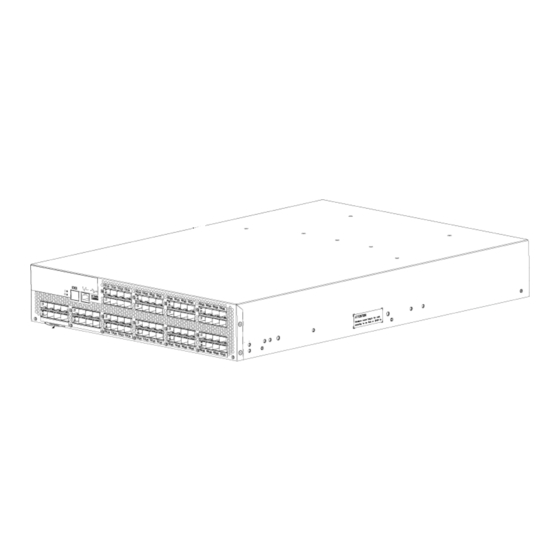
Page 19: Port Side Of The 8/40 San Switch
• Integrates a single motherboard design with 667 MHz PowerPC 440EPx Reduced Instruction Set Computer (RISC) CPU and integrated peripherals which provide high performance. • Ships FICON, FICON Cascading and FICON Control Unit Port (CUP) ready. • Provides two hot-swappable, redundant integrated power supply and fan FRUs. •... -
Page 20: Activating Additional 8/40 San Switch Ports
1. Fan (for power supply/fan FRU2) 5. Fan (for power supply/fan FRU1) 2. Power supply/fan status LED (for power supply/fan 6. Power supply/fan status LED (for Power Supply/fan FRU2) FRU 1) 3. Power supply connector (for power supply/fan 7. Power supply connector (for power supply/fan FRU FRU2) 4. -
Page 21: Port Side Of The 8/80 San Switch
Port side of the 8/80 SAN Switch The port side of the 8/80 SAN Switch includes the system status LED, console port, Ethernet port and LEDs, USB port, and FC ports with corresponding port status LEDs. Figure 4 shows the port side of the 8/80 SAN Switch. -
Page 22: Activating Additional 8/80 San Switch Ports
1 8/80 SAN Switch 5 Fan assembly #2 2 Nonport side 6 Fan assembly #1 3 Power supply #2 7 Power supply #1 4 Fan assembly #3 Figure 5 Nonport side view 8/80 SAN Switch Activating additional 8/80 SAN Switch ports By default, the 8/80 SAN Switch model integrates 48 licensed ports (ports 0 through 47). -
Page 23: Port Side Of The Encryption San Switch
• Compliance with encryption standards: AES256-XTS 1619.1 (for disk); AES256-GCM IEEE 1619.2 (for tape). NOTE: Tape support is not currently provided, but will be provided in a future release. • Smart Card • Hardware-based key management and generation • Integrated Routing Fabric Service (optional) to enable encryption capabilities across multiple fabrics •... -
Page 24: Fcoe Converged Network Switch Features
1 Status LED 2 Power LED 3 RJ-45 GE ports (for clustering and re-keying) 4 Smart Card reader 5 RJ-45 Management port 6 RJ-45 Serial Console port 7 USB port 8 Fibre Channel ports (0–31) Figure 6 Port side of the Encryption SAN Switch FCoE Converged Network Switch features The FCoE Converged Network Switch has the following features: •... -
Page 25: Port Side Of The Fcoe Converged Network Switch
• Includes Data Center Bridging eXchange (DCBX) - Capabilities Exchange and Enhanced Transmis- sion Selection (802.1Qaz) to meet the lossless and deterministic FCoE requirement. • Enables hardware-assisted MAC learning and aging. • Support for 32,768 MAC addresses and 4,096 VLANs. •... -
Page 26: Installing And Activating Port Upgrade Licenses
1. Power supply #2 4. Fan assembly #1 2. Fan assembly #3 5. Power supply #1 3. Fan assembly #2 Figure 8 Nonport side of the FCoE Converged Network Switch Installing and activating Port Upgrade licenses Use the portshow command to verify the number of ports licensed on your switch. The port status output indicates Started and Licensed for enabled ports. -
Page 27: San Switch Isl Trunking Groups
SAN Switch ISL Trunking groups All 8-Gb SAN Switch models support Inter-Switch Link (ISL) Trunking as an optional, licensed feature for FC ports. When this feature is enabled, trunked groups of up to eight contiguous ports are created. For example, the Fibre Channel ports on the SAN Switch are numbered from left to right and color-coded into groups of eight to indicate which ports you can combine into trunked groups. -
Page 28: Supported Sfp Transceiver Options
Supported SFP transceiver options Table 2 through Table 5 list the only SFPs supported in your HP StorageWorks 8-Gb SAN Switches. Table 2 FCoE Converged Network Switch long range and short range 10-Gb CEE and cable options Option Part number HP 10-GbE SR B-series SFP+ Transceiver AP823A HP 10-GbE LR B-series SFP+ Transceiver... -
Page 29: 8-Gb San Switch Software Options
8-Gb SAN Switch software options Table 6 lists the optional software kits and licenses. Table 6 Optional software kits Option Part number HP StorageWorks Full Fabric Upgrade License T4261A HP StorageWorks 8/8 and 8/24 SAN Switch 8-Gb T5518A 8-port Upgrade LTU HP StorageWorks 8/80 SAN Switch 8-Gb 16-port T5520A Upgrade LTU... - Page 30 Hardware kit Order number OM3 LC-LC type cables 0.5 m LC-LC multi-mode OM3 FC cable AJ833A 1 m LC-LC multi-mode OM3 FC cable AJ834A 2 m LC-LC multi-mode OM3 FC cable AJ835A 5 m LC-LC multi-mode OM3 FC cable AJ836A 15 m LC-LC multi-mode OM3 FC cable AJ837A 30 m LC-LC multi-mode OM3 FC cable...
-
Page 31: Installing And Configuring An 8-Gb San Switch
2 Installing and configuring an 8-Gb SAN Switch This chapter describes the following topics: • Shipping carton contents, page 31 • Installation and safety considerations, page 33 • Items required for installation, page 34 • Installing the switch as a stand-alone device, page 35 •... -
Page 32: San Switch Shipping Carton Contents
Figure 10 8/40 SAN Switch shipping carton contents Table 8 8-Gb SAN Switch shipping carton checklist Number Description One accessory kit, containing the following items: • One set of HP StorageWorks product documentation, including HP Storage- Works 8-Gb SAN Switch quick start instructions, HP StorageWorks SAN Switch Rack Mount Kit installation instructions, Read Me First, Safety Guides, User License, and Warranty •... -
Page 33: Installation And Safety Considerations
Installation and safety considerations Install the switch using one of the following methods: • “Installing the switch as a stand-alone device” on page 35 to install the unit on a flat surface. • HP highly recommends mounting the switch in one of the following HP customized racks: •... -
Page 34: Cabling Considerations
• Ground all equipment in the cabinet through a reliable branch circuit connection, and maintain ground at all times. Do not rely on a secondary connection to a branch circuit, such as a power strip. • Ensure that airflow and temperature requirements are met on an ongoing basis, particularly if the switch is installed in a closed or multirack assembly. -
Page 35: Installing The Switch As A Standalone Device
Installing the switch as a standalone device To install the switch as a standalone unit: Unpack the switch, and verify that all items listed in “Shipping carton contents” on page 31 are present. Locate the four rubber feet in the accessory box. Apply the adhesive rubber feet to the switch. -
Page 36: Installation And Safety Guidelines
Installation and safety guidelines Verify that the rack and the area around the rack meet the following requirements: • Plan a rack space that is 1.5 units high (which equals 6.7 cm or 2.6 inches), 48.3 cm (19 inches) wide, and at least 68.6 cm (23 inches) deep. For the MP Router, 4/64 SAN Switch, or 8/80 SAN Switch, plan a rack space that is at least 2 units high. -
Page 37: San Switch Rack Mount Kit Hardware
The following items are required to install the switch in a rack: • SAN Switch • Power cables • #2 Phillips screwdriver • 7/16-inch wrench or socket • Plenum (if required). For 8-Gb models, a plenum is required for 8/8 and 8/24 SAN Switches only. - Page 38 CAUTION: For proper airflow, the SFP media side of the SAN Switch must face the rear of the rack. This mounting allows air to enter the front of the rack and exhaust at the rear. To install the device in a rack: Verify that the required parts and hardware are available.
-
Page 39: Installing The Rear Mounting Brackets (Hp 10000 Series Racks)
Attach the rear mounting brackets to the rear rack uprights: • For HP 10000 series racks, assemble each of the two brackets with two #10-32 x 1/2-inch Phillips pan-head screws with captive star lock-washers and two #10 adapter washers, as shown in Figure •... -
Page 40: Installing The Outer Rails (Hp 10000 Series Racks)
Assemble the outer rails: Attach the left outer rail and the right outer rail to the rear mounting brackets, using two 1/4-20 hex nuts with captive star lock-washers attached loosely, as shown in Figure 13. Do not tighten the nuts. Figure 13 Installing the outer rails (HP 10000 series racks) Depending on the rack you are using, complete one of the following tasks: •... -
Page 41: Assembling The Outer Rails (Hp System/E Rack)
• For an HP System/e Rack, install two #10-32 x 1/2-inch Phillips pan-head screws with captive star lock-washers and two #10 alignment washers in upper and lower hole loc- ations of the right rail. Then install two #10-32 x 1/2-inch Phillips pan-head screws with captive star lock-washers and two #10 alignment washers in the upper and lower hole locations of the left rail. - Page 42 Identify the appropriate screw holes to install the inner rails to your specific device: To attach the inner rails to the 8/8 or 8/24 SAN Switches, use the five screw holes marked 8. The plenum requires one screw hole marked 8 and one screw hole marked 16, as shown Figure 18 on page 44.
-
Page 43: Securing The Inner Rails To An Mp Router
Secure the two inner rails (one on each side) to the device, using the appropriate number of screws (see Table 10). For example, Figure 16 shows an inner rail attached to the MP Router with three screws using the two rail screw holes marked R , and one marked 16. Attaching both rails require six screws. This figure also applies to the Encryption SAN Switch and the FCoE Converged Network Switch. -
Page 44: Installing The Plenum (If Required)
Installing the plenum (if required) Check to see if you are installing one of the SAN switches listed above in Step 8 and, if so, follow the steps to install the plenum: Place the device (with inner rails attached) on a flat surface (see Figure 18). -
Page 45: Cabling And Configuring The San Switch
Insert the switch with the attached inner rails into the outer rails. NOTE: This step applies to installing a switch in HP 9000 Series, HP 10000 Series, or HP System/e racks. Insert the device into the rack, and install one #10-32 x 1/2-inch Phillips pan-head screw with captive star lock washer. -
Page 46: Connecting The San Switch To The Fabric
For more information about the commands used in this procedure, see the Fabric OS Command Reference Manual for the Fabric OS version running on your switch. Connecting the SAN Switch to the fabric Connecting the SAN Switch to the fabric involves: •... -
Page 47: Making A Serial Connection
Connect the power cords to a power inlet on the switch and to a power source. Verify that the cords use a minimum service loop of 6 inches, to avoid stress. The switch powers on automatically; there is no ON/OFF switch. To power off, remove the power cord from the power source. IMPORTANT: To protect against AC failure on the 8/40 and 8/80 SAN Switches, Encryption SAN Switch, and FCoE Converged Network Switch, connect each power cord to outlets on separate... -
Page 48: Setting The Switch Ip Address
Open a terminal emulator application (such as HyperTerminal on a PC or TERM in a UNIX environment) and configure the application as follows: • In a Windows 95, 98, 2000, or NT environment: • Bits per second 9600 • Data bits 8 •... -
Page 49: Connecting An Ethernet Cable And Opening A Telnet Session
Record the IP address on the label located on the port side of the chassis. Record the IP address on the pull-out tab on the port side of the switch. If the serial port is no longer required, log out of the serial console, remove the serial cable, and replace the safety plug in the serial port. -
Page 50: Setting The Switch Date And Time
Setting the switch date and time The 8-Gb SAN Switch maintains the current date and time inside a battery-backed real-time clock (RTC) circuit. Switch operation does not depend on the date and time. An 8-Gb SAN Switch with an incorrect date and time value still functions properly. However, it is important that your switch shows the accurate date and time, because these are used for logging, error detection, and troubleshooting. -
Page 51: Setting The Time Zone
• Time zone settings persist across failover for high availability. Setting the time zone IMPORTANT: The following procedure describes how to set the time zone for a switch. You must perform the procedure on all switches for which the time zone must be set. However, you only need to set the time zone once on each switch, because the value is written to nonvolatile memory. -
Page 52: Verifying The Configuration
Enter the tsClockServer command: switch:admin> tsClockServer “<ntp1;ntp2>” where ntp1 is the IP address or DNS name of the first NTP server, which the switch must be able to access. The second ntp2 is the second NTP server and is optional. The operand “<ntp1;ntp2>”... - Page 53 The command uploads the switch configuration to the server, making it available for downloading to a replacement switch, if necessary. For detailed instructions on backing up the configuration, see the HP StorageWorks Fabric OS administrator guide. 8-Gb SAN Switch hardware reference manual...
- Page 54 Installing and configuring an 8-Gb SAN Switch...
-
Page 55: Managing The 8-Gb San Switches
3 Managing the 8-Gb SAN Switches The 8-Gb SAN Switches are designed for high availability and low failure; they do not require any regular physical maintenance. They include diagnostic tests and field-replaceable units for the HP StorageWorks 8/40 and 8/80 SAN Switches, the Encryption SAN Switch and the FCoE Converged Network Switch. -
Page 56: Configuring The Fcoe Converged Network Switch
Figure 22 Encryption configuration Configuring the FCoE Converged Network Switch See the Brocade Converged Enhanced Ethernet Administrator's Guide for details on configuring the CEE portion of the FCoE Converged Network Switch. 8-Gb SAN Switch LEDs System activity and status can be determined through the activity of the LEDs on the switch. There are three possible LED states: •... -
Page 57: 8/8 And 8/24 San Switch Leds
8/8 and 8/24 SAN Switch LEDs 8/8 and 8/24 SAN Switch LEDs are located on the port side only. 1 System power LED (green) 4 Link speed LED 2 System status LED (green/amber) 5 Port status LED (port 3) 3 Link status LED 6 Port status LED (port 7) Figure 23 Identifying 8/8 and 8/24 SAN Switch LEDs 8/40 SAN Switch LEDs... -
Page 58: 8/80 San Switch Leds
1 System status LED (top) and system power (bottom) 2 Ethernet port status LEDs (green/amber) 3 FC port status (port 9) Figure 24 Identifying 8/40 SAN Switch port side LEDs 1 Power supply 1 status LED 2 Power supply 2 status LED Figure 25 Identifying 8/40 SAN Switch nonport side LEDs 8/80 SAN Switch LEDs 8/80 SAN Switch LEDs are located on the port side and nonport side. -
Page 59: Identifying 8/80 San Switch Port Side Leds
1 8/80 SAN Switch 8 FC ports (0 through 7) 2 System status LED 9 FC ports (48 through 55) 3 Ethernet port 10 FC port status LED (port 52) 4 Ethernet speed LED 11 FC port status LED (port 48) 5 Ethernet link LED 12 Console port 6 FC port status LED (port 0) -
Page 60: Port Side Led Activity For The 8/80 San Switch
1 Power supply #2 status LED 6 Power supply #1 Status LED 2 Power supply #2 7 Power supply #1 3 Fan assembly #3 8 Fan assembly #1 status LED 4 Fan assembly #2 9 Fan assembly #2 status LED 5 Fan assembly #1 10 Fan Assembly #3 Status LED Figure 27 Identifying 8/80 SAN Switch nonport side LEDs... - Page 61 LED name LED color Status of hardware Recommended action Verify that the fan FRU and power supply FRU are seated correctly. Faulty fan FRU or power supply Replace the fan FRU or power FRU, boot failed, or the system supply FRU, if necessary. If the fan is faulty.
-
Page 62: Nonport Side Led Activity For The 8/80 San Switch
LED name LED color Status of hardware Recommended action Steady amber (for Port is receiving light or signal more than 5 carrier at 4 Gb/s, but is not yet No action required. seconds) online. Nonport side LED activity for the 8/80 SAN Switch Table 12 describes LEDs and recommended actions. -
Page 63: Port Side Led Activity For The Encryption San Switch
Port side LED activity for the Encryption SAN Switch Table 13 describes LEDs and recommended actions. Table 13 Encryption SAN Switch and FRU LEDs LED name LED color Status of hardware Recommended action System is on and functioning No light No action required. - Page 64 Slow flashing green Port is online, but segmented Verify that the correct device is at- (on 1 second, then because of a loopback cable or tached to the switch. off 1 second) incompatible switch connection. Fast flashing green Port is online and an internal (on 1/4 second, loopback diagnostic test is run- No action required.
-
Page 65: Port Side Led Activity For The Fcoe Converged Network Switch
Indicates one of the following: Try one of the following: • Fan FRU is not seated cor- • Verify that the fan FRU is rectly. seated correctly. Fan status No light • Fan FRU is not receiving • Verify that the switch is power. -
Page 66: Fcoe Converged Network Switch Port Side Led Patterns
Table 14 FCoE Converged Network Switch port side LED patterns LED name LED color Status of hardware Recommended action Verify the following: • System is powered on (power supply switches to 1) • The power cables are attached. System is off or there is an intern- No light Power status •... -
Page 67: Nonport Side Led Activity For Fcoe Converged Network Switches
Verify that the diagnostic tests are Slow blinking amber Receiving light or carrier, but not running. Re-enable the port us- (2 seconds) not online ing the portEnable command. Check the management interface Fast blinking amber and the error log for details on the Port failure (1/2 second) cause of the failure. -
Page 68: Interpreting Post Results
Table 15 describes the LEDs on the nonport side of the switch. Table 15 FCoE Converged Network Switch nonport side LED patterns LED name LED color Status of hardware Recommended action Verify the power supply is on and Power supply Power supply is not receiving seated and the power cord is con- No light... -
Page 69: Maintaining The 8-Gb San Switches
Verify that the LEDs on the switch indicate that all components are healthy. (LED patterns are described in Table 11 Table 12.) If one or more LEDs do not display a healthy state: Verify that the LEDs are not set to “beacon” (this can be determined through the switchShow command or Web Tools). -
Page 70: Diagnostic Tests
Figure 30 Installing an SFP in the upper row of port slot Diagnostic Tests In addition to POST, Fabric OS includes diagnostic tests to help you troubleshoot the hardware and firmware. This includes tests of internal connections and circuitry, fixed media, and the transceivers and cables in use. -
Page 71: 8/40 San And Fcoe Converged Network Switch Fru Units
8/40 SAN and FCoE Converged Network Switch FRU units Replace the power supply and fan assembly unit. Verifying fan assembly FRU replacement To determine if a fan assembly requires replacing, do any of the following: • Check the system status LED. If the system status LED is flashing amber and green, it could mean the fan has failed. -
Page 72: Fan Assembly Leds
Fan assembly LEDs Table 16 describes the fan status LED colors, behaviors, and actions required, if any. Table 16 Fan status LED behavior, description, and required actions LED color and behavi- Description Action required No light Fan assembly is not receiving power. Verify that the fan FRU is seated correctly. -
Page 73: 8/80 San Switch And Encryption San Switch Fru Units
Verify that the fan status LED is lit steady green to indicate normal operation. Optionally, display the fan status using the fanShow command from the CLI. 8/80 SAN Switch and Encryption SAN Switch FRU units Replace the following FRUs as required: •... -
Page 74: Replacing The 8/80 San Switch And Encryption San Switch Fan Assembly
1 8/80 SAN Switch 4 Fan assembly #2 2 Nonport side 5. Fan assembly #3 3 Fan assembly #1 Figure 32 8/80 and Encryption SAN Switch fan assemblies on the nonport side CAUTION: Disassembling any part of the fan assembly voids the part warranty and regulatory certifications. There are no user-serviceable parts inside the fan assembly. - Page 75 CAUTION: The 8/80 and Encryption SAN Switches use two power cords. Disconnect both power cords before servicing. To replace a fan assembly: Use a Phillips-head screwdriver to unscrew the captive screw on the fan assembly you are replacing. Remove the fan assembly from the chassis by pulling the handle out, away from the chassis. Install the new fan assembly in the chassis: Orient the new fan assembly as shown in Figure...
-
Page 76: Replacing An 8/80 San Switch Or Encryption San Switch Power Supply
1 8/80 SAN Switch 4 Status LED 2 Fan assembly unit 5. Handle 3 Captive screw 6. Nonport side Figure 33 Inserting the fan assembly in the 8/80 SAN Switch Replacing an 8/80 SAN Switch or Encryption SAN Switch power supply CAUTION: If a power supply fails, leave the power supply in the switch until it can be replaced. - Page 77 To replace a power supply: If the switch remains powered on, verify that the functioning power supply (the one not being replaced) has been powered on for at least four seconds and displays a green LED. If the power supply you are replacing is not already powered off, press the AC power switch to power it off.
-
Page 78: Power Supply
Gently push the power supply into the chassis until it is firmly seated. CAUTION: Do not force the installation. If the power supply does not slide in easily, make sure that it is correctly oriented before continuing. Secure the power supply to the chassis by tightening the captive screw. Plug the power cord into the power supply and then press the AC power switch to turn it on. -
Page 79: Management Tools
Table 17 Management tools Management tool Out-of-band support In-band support CLI Up to two admin sessions and four Ethernet or serial connection IP over FC user sessions simultaneously Web Tools For information, refer to the Web Tools administrator's guide for the Ethernet or serial connection IP over FC Fabric OS version running on your... - Page 80 Managing the 8-Gb SAN Switches...
-
Page 81: Encryption San Switch Specifications
4 Encryption SAN Switch specifications Table 18 provides the general specifications for the Encryption SAN Switch. Table 18 Encryption SAN Switch general specifications Specification Description Fibre Channel ports 32 FC ports universal (E, F, EX, FL, and M) Ethernet ports Two 1000 Base Ethernet ports for I/O synchronization during re-keying Smart cards Recovery card... - Page 82 Simple Name Server (SNS), Registered State Change Notification (RSCN), NTP v3, Reliable Commit Service (RCS), Dynamic Path Selection (DPS), Brocade Ad- vance Zoning (default zoning), Port/WWN zoning, broadcast zoning, NPIV, Fabric services FDML, Management Server, FSPF, Fabric Watch, Extended Fabrics, ISL, Trunking, Advanced Performance Monitor (APM), Adaptive Networking, Per data flow QoS, Ingress port rate limiting, Traffic Isolation, Group Management, Integrated Routing, and IPFC.
-
Page 83: Technical Specifications
5 Technical Specifications This chapter describes the following topics: • Weight and physical dimensions, page 83 • Memory, page 83 • Facility requirements, page 84 • Electromagnetic compatibility (EMC), page 85 • Power supply specifications, page 85 • Data transmission ranges, page 87 •... -
Page 84: Facility Requirements
Table 20 8/8, 8/24 and 8/40 SAN Switch memory Memory type Install memory Main Memory (SDRAM) 512 MB Boot Flash 8/40 SAN Switch only: 4 MB Compact Flash 1 GB Table 21 lists 8/80 SAN Switch, Encryption SAN Switch, and FCoE Converged Network Switch memory specifications. -
Page 85: Electromagnetic Compatibility (Emc)
Type Requirements 8/8, 8/24, and 8/40 SAN Switches and FCoE Converged Network Switch One rack unit in a 48.3 cm (19 in) cabinet. 8/80 and Encryption SAN Switches Cabinet space of 2U in an EIA 19-in cabinet. Cabinet (when All equipment in the cabinet grounded through a reliable branch circuit connection. rack mounted) Additional weight of the switch not to exceed the cabinet's weight limit. -
Page 86: Power Supply Specifications
Table 24 lists the power supply specifications. Table 24 Power supply specifications Specification Description Inlet 8/8 and 8/24 SAN Switches: 75 W, with fans operating 8/40 SAN Switch: 125 W, with fans operating Maximum output from each power sup- 8/80 SAN Switch: 300 W, with fans operating Encryption SAN Switch and FCoE Converged Network Switch: 350 W DC (one power supply);... -
Page 87: Data Transmission Ranges
Data transmission ranges Table 25 through Table 28 for 8-Gb SAN Switch data transmission ranges for the different cable types and port speeds. Table 25 Laser data transmission ranges for the 8/8 and 8/24 SAN Switches Port speed Cable size (microns) Short wavelength Long wavelength 1 Gb/s... -
Page 88: Laser Data Transmission Ranges For The 8/80 San Switch
Cable size (mi- Extended long Port speed Short wavelength Long wavelength crons) wavelength 10 km (6.2 miles) without an HP Extended Fabrics license 40 km (24.8 miles) 50 to 100 km with an HP Extended Fabrics license 150 m (492 ft) 4 Gb/s 62.5 70 m (230 ft) -
Page 89: Laser Data Transmission Ranges For The Encryption San Switch And The Fcoe Converged
Cable size (mi- Extended long Port speed Short wavelength Long wavelength crons) wavelength 62.5 21 m 10 km (6.2 miles) Table 28 Laser data transmission ranges for the Encryption SAN Switch and the FCoE Converged Network Switch Long wavelength Cable size (mi- Long wavelength (En- Port speed Short wavelength... -
Page 90: Fcoe Converged Network Switch Data Flow Latency
FCoE Converged Network Switch data flow latency Table 29 describes the data flow latency for the FCoE Converged Network Switch. Table 29 Data flow latency for the FCoE Converged Network Switch Data flow Size in nano- latency Type seconds FC port to FC +/–... -
Page 91: Boot
Boot In addition to POST, boot includes the following tasks after POST is complete: • Performs universal port configuration. • Initializes links. • Analyzes fabric. If any ports are connected to other switches, the switch participates in a fabric configuration. •... - Page 92 Technical Specifications...
-
Page 93: A Regulatory Compliance And Safety
Hewlett-Packard could result in the product not meeting the Class A limits, in which case the FCC could void the user's authority to operate the equipment. -
Page 94: Laser Safety Warning
Laser safety warning WARNING! To reduce the risk of exposure to hazardous radiation: Do not try to open the laser device enclosure. There are no user-serviceable components inside. Do not operate controls, make adjustments, or perform procedures to the laser device other than those specified herein. -
Page 95: International Notices And Statements
International notices and statements Canadian notice (avis Canadien) Class A equipment This Class A Digital apparatus meets all requirements of the Canadian Interference-Causing Equipment Regulations. Cet appareil numérique de la classe A respecte toutes les exigences du Règlement sur le matériel brouilleur du Canada. -
Page 96: Japanese Notice
Japanese notice Korean notices Safety Battery replacement notice Your switch is equipped with a lithium manganese dioxide, a vanadium pentoxide, or an alkaline internal battery or battery pack. There is a danger of explosion and risk of personal injury if the battery is incorrectly replaced or mistreated. -
Page 97: Taiwan Battery Recycling Notice
WARNING! Your switch contains an internal lithium manganese dioxide, a vanadium pentoxide, or an alkaline battery pack. There is risk of fire and burns if the battery pack is not properly handled. To reduce the risk of personal injury: Do not attempt to recharge the battery. Do not expose to temperatures higher than 60°C. -
Page 98: Japanese Power Cord Statement
NOTE: Route power cords so that they will not be walked on and cannot be pinched by items placed upon or against them. Pay particular attention to the plug, electrical outlet, and the point where the cords exit from the product. Japanese power cord statement Waste Electrical and Electronic Equipment directive English notice... -
Page 99: Czechoslovakian Notice
Czechoslovakian notice Estonian notice Seadmete jäätmete kõrvaldamine eramajapidamistes Euroopa Liidus See tootel või selle pakendil olev sümbol näitab, et kõnealust toodet ei tohi koos teiste majapidamisjäätmetega kõrvaldada. Teie kohus on oma seadmete jäätmed kõrvaldada, viies need elektri- ja elektroonikaseadmete jäätmete ringlussevõtmiseks selleks ettenähtud kogumispunkti. Seadmete jäätmete eraldi kogumine ja ringlussevõtmine kõrvaldamise ajal aitab kaitsta loodusvarasid ning tagada, et ringlussevõtmine toimub viisil, mis kaitseb inimeste tervist ning keskkonda. -
Page 100: German Notice
d'informations sur les centres de collecte et de recyclage des appareils mis au rebut, veuillez contacter les autorités locales de votre région, les services de collecte des ordures ménagères ou le magasin dans lequel vous avez acheté ce produit. German notice Entsorgung von Altgeräten aus privaten Haushalten in der EU Das Symbol auf dem Produkt oder seiner Verpackung weist darauf hin, dass das Produkt nicht über den normalen Hausmüll entsorgt werden darf. -
Page 101: Latvian Notice
Questo simbolo presente sul prodotto o sulla sua confezione indica che il prodotto non può essere smaltito insieme ai rifiuti domestici. È responsabilità dell'utente smaltire le apparecchiature consegnandole presso un punto di raccolta designato al riciclo e allo smaltimento di apparecchiature elettriche ed elettroniche. -
Page 102: Portuguese Notice
Portuguese notice Descarte de Lixo Elétrico N/A Comunidade Européia Este símbolo encontrado no produto ou N/A embalagem indica que o produto não deve ser descartado no lixo doméstico comum. É responsabilidade do cliente descartar o material usado (lixo elétrico), encaminhando-o para um ponto de coleta para reciclagem. A coleta e a reciclagem seletivas desse tipo de lixo ajudarão a conservar as reservas naturais;... -
Page 103: Swedish Notice
de recogida de residuos eléctricos y electrónicos para reciclado, póngase en contacto con su ayuntamiento, con el servicio de eliminación de residuos domésticos o con el establecimiento en el que adquirió el producto. Swedish notice Bortskaffande av avfallsprodukter från användare i privathushåll inom Europeiska Unionen Om den här symbolen visas på... - Page 104 Regulatory compliance and safety...
-
Page 105: B Electrostatic Discharge
B Electrostatic discharge This appendix provides the following information: • How to prevent electrostatic discharge, page 105 • Grounding methods, page 105 How to prevent electrostatic discharge To prevent damage to the system, you must follow certain precautions when setting up the system or handling parts. - Page 106 Electrostatic discharge...
-
Page 107: Index
Index configuring Symbols cabling and configuring, 45 8/8 SAN switch connecting an Ethernet cable, 49 features, 17 ezswitch setup, 46 making a serial connection, 47 opening a Telnet session, 49 SAN encryption switch, 55 audience, 11 setting time zone, 51 setting switch data and time, 50 setting the domain... - Page 108 Ethernet installation connecting cable, 49 as standalone device, 35 items required for, 34 rack mount kit, 36 safety guidelines, 36 fabric securing switch to outer rails, 44 connecting SAN switch to, 46 using the rack mount kit, 35 fabricshow command, 52 installation considerations, 33 facility...
- Page 109 POST, 90 interpreting results, 68 Taiwan battery recycling notice, 97 specifications, 90 technical support power supply HP, 13 specifications, 85 technical support powering on the 8-Gb SAN Switch, 47 service locator website, 14 psshow command, 78 Telnet session opening, 49 text symbols, 12 time zones...
Need help?
Do you have a question about the StorageWorks 8/40 - SAN Switch and is the answer not in the manual?
Questions and answers