
Related Manuals for TANDBERG TT-1222


Summary of Contents for TANDBERG TT-1222
- Page 1 ST.RE.TT1222.2 Issue 2 ENGLISH (UK) REFERENCE GUIDE TT1222 4:2:0 Professional Receiver Software Version 2.0.0 (and later) TT1222 4:2:0 Professional Receiver...
-
Page 2: Reference Guide: Tt1222 4:2:0 Professional Receiver
This document and the information contained in it is the property Issue 2 first published in 2005 by: of TANDBERG Television Ltd and may be the subject of patents ANDBERG ELEVISION pending and granted. It must not be used for commercial... - Page 3 Preliminary Pages List of Contents Chapter 1: Introduction This chapter describes the purpose of the TT1222 in a typical system, provides a summary of its main features and identifies the controls. Chapter 2: Installing the Equipment This chapter provides a guide to installing the equipment, including the suitability of an installation, detailed procedures for the preparation, installation and configuration.
- Page 4 Preliminary Pages About This Reference Guide This Reference Guide provides instructions and information for the installation and operation of the TT1222 4:2:0 Professional Receiver. It should be kept in a safe place for reference for the life of the equipment. It is not intended that this Reference Guide is amended by the issue of individual pages.
- Page 5 Preliminary Pages Warnings, Cautions and Notes Heed Warnings All warnings on the product and in the operating instructions should be adhered to. The manufacturer cannot be held responsible for injuries or damage where warnings and cautions have been ignored or taken lightly. Read Instructions All the safety and operating instructions should be read before this product is operated.
-
Page 6: Support Services
TANDBERG Television and your business. Warranty All TANDBERG Products and Systems are designed and built to the highest standards and are covered under a comprehensive 12 month warranty. Levels of Continuing TANDBERG Television Service Support For stand-alone equipment, then TANDBERG Television BASIC Advantage is the value for money choice for you. -
Page 7: Technical Training
Preliminary Pages Technical Training Training Courses TANDBERG Television provides a wide range of training courses on the operation and maintenance of our products and on their supporting technologies. TANDBERG can provide both regularly scheduled courses and training tailored to individual needs. Courses can be run either at your premises or at one of our dedicated training facilities. - Page 8 Preliminary Pages BLANK Page viii Reference Guide: TT1222 4:2:0 Professional Receiver ST.RE.TT1222.2...
-
Page 9: Table Of Contents
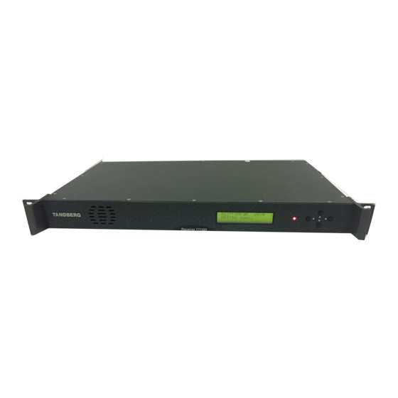
Chapter 1 Introduction Contents List of Figures 1.1 Scope of This Reference Guide........ 1-3 Figure 1.1: Front View ..............1-3 1.1.1 Who Should Use This Reference Guide..1-3 Figure 1.2: Navigating the Menus..........1-7 1.1.2 What Equipment is Covered by This Figure 1.3: Editing Values in a Menu.......... - Page 10 Introduction BLANK Page 1-2 Reference Guide: TT1222 4:2:0 Professional Receiver ST.RE.TT1222.2...
-
Page 11: Scope Of This Reference Guide
Scope of This Reference Guide 1.1.1 Who Should Use This Reference Guide This Reference Guide is written for operators/users of the TANDBERG TT1222 Professional Receiver. It describes the unit’s functions and operation. The Reference Guide is written to assist in the installation and day-to-day care and operation of the unit. -
Page 12: Summary Of Features
Introduction Summary of Features 1.2.1 Main Features The Receiver is fully compliant with the appropriate sections of the MPEG-2 and DVB-S specifications. The TT1222 offers the following features: • Signal Inputs: QPSK L-Band (Option) 1 x QPSK via F-connector ASI input (Option) 1 x ASI via BNC connector •... -
Page 13: Outputs
LCD display Single LED provides status information • Data: Low speed data: RS-232 asynchronous (up to 115.2 kbit/s) • Remote Control: RS-232, TANDBERG proprietary control solution • Control 1 Relay available 5 General Purpose Outputs 1.2.2 Outputs Video Outputs Two BNC composite video outputs are present on the rear of the unit. -
Page 14: Conditional Access
Introduction 1.2.3 Conditional Access The transport stream received by the IRD may be encrypted. The CA system is used to decrypt the required components of the transport stream so that they can be decoded. The following conditional access system is available on the TT1222 Receiver. -
Page 15: Guided Tour
Introduction Guided Tour 1.4.1 Construction The Receiver is constructed using a screened fan-ventilated chassis. All operational inputs and outputs are via the rear panel connectors. The unit may be operated freestanding on a horizontal flat surface, or mounted in a 19-inch rack. -
Page 16: Edit And Save
Introduction Edit and Save In the edit mode, when the correct value is in place, exit and save by pressing multiple times to the right, to move the cursor outside the edit area. When the cursor leaves the edit area, the new setting will be saved, and the keypad will revert to the navigation mode. - Page 17 Chapter 2 Installing the Equipment Contents 2.5.4 Connecting the Equipment to the AC 2.1 Read this First!............2-3 Power Supply..........2-8 2.1.1 Handling ............2-3 2.6 Signal Connections............2-9 2.1.2 Installing the Equipment ....... 2-3 2.6.1 Overview ............2-9 2.1.3 Lifting ............2-3 2.6.2 Input Connectors...........2-9 2.1.4 Site Requirements ........
- Page 18 Installing the Equipment Table 2.8: RS-232 Connector............2-14 Table 2.9: Conditional Access............. 2-14 Page 2-2 Reference Guide: TT1222 4:2:0 Professional Receiver ST.RE.TT1222.2...
-
Page 19: Read This First
IF THE UNIT HAS BEEN SUBJECT TO A LIGHTNING STRIKE OR POWER SURGE WHICH HAS STOPPED IT WORKING, DISCONNECT THE POWER IMMEDIATELY. DO NOT REAPPLY POWER UNTIL IT HAS BEEN CHECKED FOR SAFETY. IF IN DOUBT, CONTACT TANDBERG TELEVISION CUSTOMER SERVICES. -
Page 20: Preliminary Checks
TANDBERG Television Customer Services (see Preliminary pages). WARNING… REMOVING THE COVERS OF THIS EQUIPMENT MAY INVALIDATE ANY WARRANTIES, CAUSE A SAFETY HAZARD AND / OR AFFECT THE EMC PERFORMANCE. CHECK WITH TANDBERG TELEVISION CUSTOMER SERVICES. 2.2.2 Moving the Equipment Safely Do not place this product on an unstable cart, stand, bracket, or table. -
Page 21: Care In Positioning
Installing the Equipment Care in Positioning CAUTIONS… The fan and openings contained within this unit are not fitted with a dust / insect filter. Pay attention to the environment in which it is to be used. Do not install units so that the air intake for one unit aligns with the outlet of another. Provide baffles and adequate spacing. -
Page 22: Emc Compliance Statements
Installing the Equipment EMC Compliance Statements 2.4.1 EN 55022 and AS/NZS 3548 This is a Class A product. In a domestic environment this product may cause radio interference in which case the user may be required to take adequate measures. 2.4.2 This equipment have been tested and found to comply with the limits for a Class A digital device, pursuant to part 15 of the FCC rules. -
Page 23: Technical Earth
Installing the Equipment NOTE… There is no user-replaceable fuse in the rear of the unit. 2.5.2 Technical Earth The Technical Earth provides a suitable connection between the TT1222 and the installation to give a low impedance path at normal operating frequencies. -
Page 24: Disposal Of Moulded Plugs
Installing the Equipment Disposal of Moulded Plugs If the moulded plug fitted to the mains cable supplied with this equipment is not required, use another cable. If the supplied plug is to be changed, cut it off and dispose of it safely. WARNING…... -
Page 25: Signal Connections
Installing the Equipment Signal Connections 2.6.1 Overview Figure 2.3 shows the signal connections for the TT1222 Receiver and options. TT1222 Professional Receiver Motherboard (TT1222 / CIBAS) Conditional Access PCMCIA slot CONDITIONAL ACCESS INTERFACE 1 x Relay and 5 x General Purpose RELAY/GPO Outputs Low Speed Asynchronous Data... -
Page 26: Asi Input (Tt1222/Hwo/Asi/In)
Installing the Equipment ASI Input (TT1222/HWO/ASI/IN) See Chapter 3, Options for details. RS232 Remote The RS-232 connector labelled remote on the back of the equipment allows for connection to a PC for remote control, software upload or debug purposes. The SETUP ⇒ OUTPUTS ⇒ RS232 ⇒ REMOTE menu is used to configure the parameters for communicating with the unit. -
Page 27: Analogue/Digital Audio Outputs
NOTE… Dolby AC-3 decoding shall be enabled and disabled by licence key. For more information, please contact TANDBERG Television Customer Services. See Chapter 3 for details of Options Reference Guide: TT1222 4:2:0 Professional Receiver Page 2-11... -
Page 28: Audio Lead
Installing the Equipment Audio Lead Two audio cables are supplied with TT1222 units, as shown in Figure 2.5. These cables support analogue left and right channels and unbalanced digital audio. Figure 2.5: Audio Cable ASI Output (TT1222/HWO/ASI/OUT) See Chapter 3, Options for details. RS-232 Low-speed Asynchronous Data Output A 9-way D-type female connector is provided as the connection for low-speed data output. -
Page 29: Alarm Relay/General Purpose Output
Installing the Equipment Table 2.6: RS-232 Low-speed Data Connector Item Specification Connector type 9-way D-type, Female Connector designation RS232 DATA Output rate 75, 110, 150, 200,300, 600, 1050, 1200, 2400, 4800, 9600, 19200, 38400, 57600 or 115200 baud selectable Pin-outs Function Reserved Data Transmit (Tx) - data output... -
Page 30: Rs232 Remote
Installing the Equipment 2.6.4 RS232 Remote The RS-232 connector labelled remote on the back of the equipment allows for connection to a PC for remote control, software upload or debug purposes. The SETUP ⇒ OUTPUTS ⇒ RS232 ⇒ REMOTE menu is used to configure the parameters for communicating with the unit. - Page 31 Chapter 3 Options Contents List of Tables 3.1 Available Options ............3-3 Table 3.1: Hardware Options............3-3 3.1.1 Hardware Options......... 3-3 Table 3.2: Software Options ............3-3 3.1.2 Software Options .......... 3-3 Table 3.3: QPSK Satellite Receiver (L-band) Connector ....3-4 3.2 Hardware Enabled Input Options......
- Page 32 Options BLANK Page 3-2 Reference Guide: TT1222 4:2:0 Professional receiver ST.RE.TT1222.2...
-
Page 33: Available Options
Options Available Options 3.1.1 Hardware Options These options require extra hardware to be fitted to the unit. Contact the Customer Services Helpdesk for details (see Preliminary Pages). Table 3.1 lists all the different types of option cards that are supported in this release. -
Page 34: Hardware Enabled Input Options
Options Hardware Enabled Input Options 3.2.1 Limitations The TT1222 can not be fitted with the ASI input option and QPSK input option at the same time. 3.2.2 ASI Input (TT1222/HWO/ASI/IN) General The ASI Input card supports ASI transport stream on a single BNC connector. -
Page 35: Use Of An Attenuator
Options CAUTIONS… 1. The Receiver provides dc power via the active L-band input connector to drive an LNB (Low Noise Block Down-Converter). Do not connect equipment other than an LNB to this connector. Failure to do this may result in damage to the external equipment The F-type connector is not suitable for repeated connection and disconnection. -
Page 36: Hardware Enabled Output Options
Options Hardware Enabled Output Options 3.3.1 ASI Output (TT1222/HWO/ASI/OUT) General The TT1222 provides a single ASI output on a BNC connector. Connector Details 75 Ω BNC connector. Setting up the ASI Output The output can be set to be scrambled or descrambled. Table 3.5: Setting up the ASI Output Output Description... - Page 37 Options Output Description Field+notch Chrominance subcarrier reference signals occupying nine lines of field-blanking period on Lines 7 to 15 in Fields 1 and 3 and Lines 320 to 328 in Fields 2 and 4. Also has a luminance trap filter active in the VBI. B/W+notch No chrominance subcarrier is present (monochrome output).
- Page 38 Options BLANK Page 3-8 Reference Guide: TT1222 4:2:0 Professional receiver ST.RE.TT1222.2...
- Page 39 Chapter 4 Operating the Equipment Locally Contents List of Figures 4.1 Powering the Equipment........... 4-3 Figure 4.1: Status Display ............. 4-3 4.1.1 Switching On ..........4-3 4.1.2 Front Panel Keypad........4-3 List of Tables 4.2 Using the Local Controls........... 4-4 4.2.1 Menu Tree ............
- Page 40 Operating the Equipment Locally BLANK Page 4-2 Reference Guide: TT1222 4:2:0 Professional Receiver ST.RE.TT1222.2...
-
Page 41: Powering The Equipment
Operating the Equipment Locally Powering the Equipment 4.1.1 Switching On Connect the TT1222 to the signal inputs and the AC power supply and turn it on. There is a short boot period. After the boot period, the unit displays the default status view, showing the current condition. -
Page 42: Menu Tree
Operating the Equipment Locally Using the Local Controls 4.2.1 Menu Tree See Annex C, Section C.2. 4.2.2 Selecting a (Sub)Menu Item Selecting the Menu Item To select a menu item, navigate using the Up and Down arrow key until the desired menu is displayed in front of the cursor. Press the Right arrow to select / enter this menu item. -
Page 43: Service Configuration
Operating the Equipment Locally Service Configuration 4.4.1 Selecting a Service Setting Up a Service Each transport stream may contain a multitude of services and types. The TV service and Audio 2 service menus, located in the Setup menu, allows the user to select the services to be decoded. -
Page 44: Setting Up An Additional Audio Channel
Operating the Equipment Locally 4.4.2 Setting Up an Additional Audio Channel Configuring this output is very similar to configuring the TV output. NOTE… Audio 1 is associated with the TV Service. An additional audio is available and referred to as “Audio 2”. To set up the Audio 2 service, select the service and language according to Table 4.3. - Page 45 Chapter 5 Operating the Equipment Remotely Contents List of Tables 5.1 Remote Control............5-3 Table 5.1: Configuring the Communication Parameters ....5-3 5.1.1 Introduction........... 5-3 Table 5.2: Activating RS-232 Remote Control ......5-4 5.1.2 Remote Protocol Control Documentation ..5-3 Table 5.3: Configuring the Unit for Local Control ......
-
Page 46: Operating The Equipment Remotely
Operating the Equipment Remotely BLANK Page 5-2 Reference Guide: TT1222 4:2:0 Professional Receiver ST.RE.TT1222.2... -
Page 47: Remote Control
NOTE… The TT1222 remote control methods (listed above) are designed to be backwards compatible with the TANDBERG TT1220 receiver. This means the TT1222 can be used as a replacement product in existing TT1220 systems where remote control is used. 5.1.2 Remote Protocol Control Documentation The protocol used for remote control is the TANDBERG RS-232 control. -
Page 48: Returning The Unit To Local Control Mode
Operating the Equipment Remotely Once the communication parameters are entered correctly, set the system into remote mode for the external computer to gain control of the unit. Table 5.2: Activating RS-232 Remote Control Step Action Result Go to the Control menu, located under The display will read “SET:CONTROL”... - Page 49 Chapter 6 Alarms/GPOs Contents List of Figures 6.1 Alarm Configuration ..........6-3 Figure 6.1: Relay/GPO Connector..........6-5 6.1.1 Alarm Configuration of the TT1222 ....6-3 6.1.2 Changing the Alarm Configuration ....6-3 List of Tables Table 6.1: Alarm Categories............6-3 6.2 Front Panel Alarm Indicators........
- Page 50 Alarms/GPOs BLANK Page 6-2 Reference Guide: TT1222 4:2:0 Professional Receiver ST.RE.TT1222.2...
-
Page 51: Alarm Configuration
Alarms/GPOs Alarm Configuration 6.1.1 Alarm Configuration of the TT1222 The TT1222 has a multitude of possible error conditions. All of these error conditions generate error messages, which are user configurable, and each message may be given three different states of severity. They are Ignore, Warning, and Alarm. -
Page 52: Front Panel Alarm Indicators
Alarms/GPOs Table 6.2: Navigating the Alarm Configuration Menus Step Action Result Go to the Alarm setup menu, located The display will read “SET:SELECT ALARMS” on the under Setup ⇒ Outputs ⇒ Alarms top line. ⇒ Select Alarms. Using the up and down arrows, select Scrolling up and down will now reveal all alarm an alarm category for modification, messages associated with this alarm category. -
Page 53: Menu Driven Alarm Indications
Alarms/GPOs Menu Driven Alarm Indications Once the TT1222 is in a warned or alarmed state, the easiest way for the user to diagnose the alarm condition is via the status menu. Table 6.3: Navigating the Alarm Status Menus Step Action Result Go to the Alarm menu, located under The display will read “STAT:ALARM”... -
Page 54: Setting Up The Gpos Configuration
Alarms/GPOs The outputs are not suitable for driving general purpose 5V relays which have a coil resistance of less than 167 Ω. The GPOs can not be activated on power failure. Setting up the GPOs Configuration The TT1222 has 5 General Purpose Outputs which can be set up to trigger on one or more events. -
Page 55: Alarms/Gpos
Alarms/GPOs Table 6.6: Navigating the GPO Configuration Menus Step Action Result Go to the GPO setup menu, located The display will read “SET:GPOs” on the top line. under Setup ⇒ Outputs ⇒ GPOs. Using the up and down arrows, select a Scrolling up and down will now reveal all available GPO to be set up. - Page 56 Alarms/GPOs BLANK Page 6-8 Reference Guide: TT1222 4:2:0 Professional Receiver ST.RE.TT1222.2...
- Page 57 7.2.3 Check on Completion of Servicing ....7-4 7.3 Maintenance and Support Services ......7-4 7.3.1 Introduction........... 7-4 7.3.2 Warranty ............7-4 7.3.3 Levels of Continuing TANDBERG Television Service Support......7-4 7.3.4 Extended Warranty........7-4 7.4 Factory Default Settings..........7-5 7.5 Fault-finding ..............
- Page 58 Preventive Maintenance and Fault-finding BLANK Page 7-2 Reference Guide: TT1222 4:2:0 Professional Receiver ST.RE.TT1222.2...
-
Page 59: Routine Checks
4. If the product does not operate normally by following the operating instructions. Adjust only those controls that are covered by the operating instructions or as told by a TANDBERG Television engineer. Failure to do so may render the product in an unstable state; and may... -
Page 60: Replacement Parts
Extended Warranty NOTE… The above warranty is the basic warranty on TANDBERG Television products. This warranty might be extended through a separate deal or purchase made with TANDBERG Television. Refer to the service contract (if any) that came with your equipment or system for further information. -
Page 61: Factory Default Settings
Preventive Maintenance and Fault-finding Factory Default Settings The TT1222 is dispatched with the following factory defaults. These can be restored at any time using the Restore Def: option found in the Setup ⇒ System submenu. Table 7.1: Factory Defaults Menu Item Default SET: VIDEO... -
Page 62: Fault-Finding
Preventive Maintenance and Fault-finding Fault-finding 7.5.1 General The information contained in this chapter is intended to isolate the unit as the faulty equipment if a system failure occurs. If the following information fails to clear the abnormal condition, please contact Customer Services using the information given in the Preliminary pages of this Reference Guide. - Page 63 Annex A Glossary The following list covers most of the abbreviations, acronyms and terms as used in TANDBERG Television Limited Manuals, User and Reference Guides. All terms may not be included in this Reference Guide. µm Micrometre (former name - micron): a unit of length equal to one millionth (10 ) of a metre.
- Page 64 Glossary B3ZS Bipolar with Three Zero Substitution: A method of eliminating long zero strings in a transmission. It is used to ensure a sufficient number of transitions to maintain system synchronisation when the user data stream contains an insufficient number of 1s to do so. B3ZS is the North American equivalent of the European HDB3. Backward Compatibility Refers to hardware or software that is compatible with earlier versions.
- Page 65 Glossary Compression Reduction in the number of bits used to represent the same information. For the purposes of a broadcast system, it is the process of reducing digital picture information by discarding redundant portions of information that are not required when reconstituting the picture to produce viewing clarity. Compression allows a higher bite-rate to be transmitted through a given bandwidth.
- Page 66 Group of Pictures: MPEG video compression works more effectively by processing a number of video frames as a block. The TANDBERG Television Encoder normally uses a 12 frame GOP; every twelfth frame is an I frame. Graphical User Interface: The use of pictures rather than just words to represent the input and output of a program.
- Page 67 Glossary Interframe Coding Compression coding involving consecutive frames. When consecutive frames are compared, temporal redundancy is used to remove common elements (information) and arrive at difference information. MPEG-2 uses B and P frames, but since they are individually incomplete and relate to other adjacent frames, they cannot be edited independently.
- Page 68 MCPC Multiple Channels Per Carrier. Multiplex Element Manager: A GUI based control system, part of the range of TANDBERG Television compression system control element products. The evolution 5000 MEM holds a model of the system hardware. Using this model, it controls the individual system elements to configure the output multiplexes from the incoming elementary streams.
- Page 69 Glossary NVOD Near Video On Demand: Method of offering multiple showings of movies or events. The showings are timed to start at set intervals, determined by the broadcaster. Each showing of a movie or event can be sold to subscribers separately.
- Page 70 Random Access Memory: A volatile storage device for digital data. Data may be written to, or read from, the device as often as required. When power is removed, the data it contains is lost. Remote Authorization System: A TANDBERG TV proprietary public-key encryption system used to prevent unauthorized viewing of a TV programme or programmes.
- Page 71 Glossary Single Packet Burst Mode A burst of ASI bytes (either 188 or 204, depending on packet length) is contiguously grouped into an MPEG-2 Transport Stream packet. Stuffing data is added between the packets to increase the data rate to 270 Mbit/s. See DVB Document A010 rev.
- Page 72 Glossary Uninterruptable Power Supply: A method of supplying backup power when the electrical power fails or drops to an unacceptable voltage level. Small UPS systems provide battery power for a few minutes; enough to power down the computer in an orderly manner. This is particularly important where write back cache is used. Write back cache is where modified data intended for the disk is temporarily stored in RAM and can be lost in the event of a power failure.
- Page 73 Annex B Technical Specification Contents B.11.1 Safety............B-13 B.1 General ..............B-3 B.11.2 EMC ............B-14 B.2 Key Features.............B-3 B.11.3 CE Marking ..........B-14 B.11.4 C-Tick Mark..........B-14 B.3 Video Decoder ............B-3 B.11.5 Recommended Cable Types...... B-15 B.4 Outputs ..............B-4 List of Tables B.4.1 Analogue Video Output ........B-4 Table B.1: Video Decoder .............B-3 B.4.2 Composite 625 Lines Output ......B-4...
- Page 74 Technical Specification BLANK Page B-2 Reference Guide: TT1222 4:2:0 Professional Receiver ST.RE.TT1222.2...
-
Page 75: General
Technical Specification General The TT1222 is a 1RU single channel MPEG-2 Receiver, designed to decode DVB compliant MP@ML MPEG-2 transport streams. Key Features • Optional inputs: QPSK, ASI (refer to Chapter 3 for details) • Optional output: ASI, Russian SECAM (refer to Chapter 3 for details) •... -
Page 76: Outputs
Technical Specification Outputs B.4.1 Analogue Video Output Two BNC composite analogue video outputs are provided on the Rear Panel of the unit. Table B.2: Analogue Video Output Parameter Performance Safety status: SELV Connector type: 2 x BNC (female) 75 Ω Impedance: Chroma / Luminance gain error 100 +/- 3%... -
Page 77: Composite 525 Lines Output
Technical Specification From leading edge of line-blanking signal up to Chroma subcarrier blanking: ± µ i = 5.6 0.2 ( s) after epoch O During field-blanking interval, excluding frame identification signals, or, in countries where this is possible, during the whole of the field-blanking interval. Refer to ITU-R BT.470-6 for details Field identification lines: Lines 7 to 15 and lines 320 to 328 inclusive. -
Page 78: Vbi 625 Lines Output
Technical Specification B.4.5 VBI 625 Lines Output Table B.6: 625 Line VBI Output Parameter Line/Field Performance VITS lines specification ITU-R J.63 VITS PAL (lines) 17, 18, 330, 331 VITS SECAM (lines) 17, 18 VITC lines 16 or 22 (fields 1 SMPTE RP164, and 2) ISO 13818-2 GOP header... -
Page 79: Audio Decoder
Technical Specification B.4.7 Audio Decoder Table B.8: Audio Decoder Parameter Performance Supported formats: MPEG-1 layer 1, MPEG-1 layer 2 (MUSICAM) Dolby AC-3 Downmix Output format option: Audio 1 and Audio 2:Balanced analogue and S/PDIF B.4.8 Analogue Audio Output Table B.9: Analogue Audio Output Specification Parameter Performance Safety status:... -
Page 80: Data Communication
Technical Specification Data Communication B.5.1 Low Speed Data Table B.11: LS Data Configuration Parameter Performance Safety status: SELV Output connector: 9 pin D-sub (female) Electrical format: RS-232 Data rates: 75, 110, 150, 200,300, 600, 1050, 1200, 2400, 4800, 9600, 19200, 38400, 57600 or 115200 baud selectable Tolerance: 2.5 %... -
Page 81: Alarm Relay/General Purpose Output
Technical Specification Alarm Relay/General Purpose Output Table B.13: Alarm Relay Parameter Specification Safety status SELV Output connector Female 9 pin D-sub Electrical format Mechanical relay, contact closure Number of signals Contact resistance 50 mΩ Max switching voltage (AC/DC) 30 V / 120 V Max switching power (AC/DC) 120 VA / 24 W Surge voltage - contact coil... -
Page 82: Options
Technical Specification Options B.7.1 QPSK Input Option (TT1222/HWO/QPSK) The satellite input interface shall be compliant with the DVB specification. The LNB supply shall meet the requirements of IEC1319-1 (IEC61319-1) for European satellite receiver interfaces. Any requirements specific to Japan and USA are not included. Relevant requirements are summarized in Table B.15. -
Page 83: Asi Input Option (Tt1222/Hwo/Asi/In
Technical Specification B.7.2 ASI Input Option (TT1222/HWO/ASI/IN) The ASI interface is implemented in accordance with CENELEC EN 50083-9: ref [15], in particular Annex B and E. Table B.16: ASI Input Parameter Specification Safety status SELV 1 x BNC, female 75 Ω Input connector Sustained transport stream data rate 72 Mbit/s... -
Page 84: Russian Secam Output Option (Tt1222/Hwo/Rs
Technical Specification B.7.4 Russian SECAM Output Option (TT1222/HWO/RS) The Russian SECAM output module offers ITU-R BT470-6/GOST 7845-92 compliant Russian SECAM for systems D and K. When the module is fitted both CVBS outputs of the receiver can be configured to have field identification lines (also Known as “bottles”). Power Supply This equipment is fitted with an wide-ranging power supply. -
Page 85: Environmental Conditions
Technical Specification B.10 Environmental Conditions Table B.20: Environmental Specification Item Specification Operational Temperature 0°C to +50°C (14°F to 122°F) ambient with free air-flow Relative humidity 0% to 95% (non-condensing) Cooling requirements Cool air input from front panel, exhaust from right and left side of unit Handling/movement Designed for stationary or fixed use when in operation Storage/Transportation... -
Page 86: Emc
Technical Specification B.11.2 EMC The equipment has been designed and tested to meet the following: EN 55022 European Emission Standard Limits and methods of measurement of CISPR22 International radio frequency interference characteristics of information technology equipment - Class A. EN 61000-3-2 European Electromagnetic Compatibility (EMC), Part 3 Limits;... -
Page 87: Recommended Cable Types
Connector Recommended Cable CVBS 1 / CVBS 2 Canford 1/3 PSF (type 2 video cable) Audio 1 / Audio 2 9-Way D-Type Please contact TANDBERG Television Customer Services (see Preliminary pages). Relay/GPO 9-Way D-Type Belden 8162 CM2PR24 RS232 Data 9-Way D-Type... - Page 88 Technical Specification BLANK Page B-16 Reference Guide: TT1222 4:2:0 Professional Receiver ST.RE.TT1222.2...
- Page 89 Annex C Front Panel LCD Menus Contents C.5.13 Outputs Setup Menu ........C-19 C.1 LCD Menus ...............C-3 C.5.14 Alarms Menu..........C-19 C.1.1 Using the Menus...........C-3 C.5.15 Select Alarms Menu........C-19 C.1.2 Menu Descriptions........C-3 C.5.16 CVBS Output Menu........C-20 C.1.3 Menu Controls ..........C-3 C.5.17 GPOs Menu ..........
-
Page 90: List Of Figures
Front Panel LCD Menus C.6.11 PID Info Menu ..........C-34 Table C.39: BISS E User ID Setup Menus........C-27 Table C.40: System Setup Menu ..........C-28 C.6.12 TV Service PID Info Menu......C-34 Table C.41: Control Setup Menu..........C-28 C.6.13 Audio 2 Service PID Info Menu....C-35 Table C.42: Status Menu Items...........C-29 C.6.14 CA Module Menu ........ -
Page 91: Lcd Menus
Front Panel LCD Menus LCD Menus C.1.1 Using the Menus Detailed description of the use of menus is given in Chapter 4, Operating the Equipment Locally. C.1.2 Menu Descriptions This annex describes the front panel LCD menus. The menu is created in a tree structure, where each branch may contain items, new branches, or both. -
Page 92: Unlocking The Front Panel
Front Panel LCD Menus Unlocking the Front Panel: The unlocking sequence is required if the locked indicator is present on the top left line. The sequence is Left, Right, Left, Left, Left, Right, Right, Right. Protected Menus: Setup menus inside the menu tree may be protected for unauthorised access. -
Page 93: Menu Tree
Front Panel LCD Menus Menu Tree PRESETS PRESETS:SELECT SET:TV SERVICE MAIN MENU Select > ->P00: Program 1 Service ID > SET:TV SERVICEID SET:VIDEO SETUP SET:VIDEO 625 Presets > Add > _ P01: Not used Aud1 Type: Musicam Service ID: 625 Setup > 625 Video: Setup >... -
Page 94: Menu Pages - Main Menu
Front Panel LCD Menus Menu Pages - Main Menu The main menu is a pure branching menu. No items are selectable in this menu, it only allows access to other, lower level menus, which are described in individual sections. Table C.1: Main Menu Items Menu title: Main Menu Description Section... -
Page 95: Presets Menu
Front Panel LCD Menus Presets Menu C.4.1 Presets Menu Items Provides access to menus that allow the user to store and retrieve service selections. Table C.2: Presets Menu Menu title: PRESETS Description Section Select > Enters the service selection sub menu. C.4.2 Add >... -
Page 96: Tv Service Menu
Front Panel LCD Menus Menu title: SETUP Description Section Outputs > Enters the Outputs setup submenu. C.5.13 CA > Enters the CA (Conditional Access) setup submenu C.5.25 System > Enters the System submenu C.5.32 Control > Enters the Control submenu C.5.33 Factory >... -
Page 97: Tv Service Id
Front Panel LCD Menus Menu title: SET:TV SERVICE Description Section DVB Pref: Allows the selection of formatting the DVB subtitles in conjunction ---- with format conversion and wide screen signalling. A preferred format can be specified. If the preferred format is present in the stream in the chosen language (DVB Sub Lang), the subtitles will be displayed in the chosen format. -
Page 98: Audio 2 Service Id
Front Panel LCD Menus Table C.8: Audio2 Service Menu Menu title: SET:AUD2 SERVICE Description Section Service ID > Display or change the service ID for the decoded service. C.5.5 Track Audio 1: Audio 2 can be set to track Audio 1. ---- Off: Audio 2 can be set to decode a different audio service. -
Page 99: Video 625 Setup Menu
Front Panel LCD Menus C.5.7 Video 625 Setup Menu The Video setup 625 menu contains all the parameters that affect the 625 line Video, other than the basic selection of Video service and language. Table C.11: Video 625 Setup Menu Menu title: SET:VIDEO 625 Description Section... - Page 100 Front Panel LCD Menus Menu title: SET:VIDEO 625 Description Section WSS: Wide screen signalling. Selects decoding of the WSS information ---- into the VBI area. On (DVB) - WSS will be regenerated as sent in the WSS PID. MPEG-video - WSS will be regenerated as sent in the Video Packet header of the video stream.
- Page 101 Front Panel LCD Menus Menu title: SET:VIDEO 625 Description Section SECAM Enables the Russian SECAM subcarrier reference signal to be ---- configured. LineID - Chrominance subcarrier reference signals are inserted into the back porch of the line blanking period. Line+notch - As LineID but also has a luminance trap filter active in the Vertical Blanking Interval (VBI).
-
Page 102: Video 525 Setup Menu
Closed Cap: Activates closed caption reinsertion onto line 21. ---- Auto - Detects and decodes, if present, ATSC or TANDBERG Proprietary formatted closed captioning. Off - Closed caption VBI insertion is turned off. C-Cube - Decoding of C-Cube formatted closed captioning is turned on. -
Page 103: Default Output Menu
Front Panel LCD Menus C.5.9 Default Output Menu If the receiver losses its input signal, input lock or has decoding errors, the video output will default to a legal output. Table C.13: Default Output Setup Menu Menu title: SET:DEFAULT O/P Description Section Line Standard... -
Page 104: Audio 1 (Tv) And Audio 2 Setup Menus
Front Panel LCD Menus C.5.11 Audio 1 (TV) and Audio 2 Setup Menus The audio setup menus allows the user to configure and control each audio output. Table C.15: Audio 1 and 2 Setup Menu Menu title: SET:AUDIO 1, Description Section SET:AUDIO 2 O/p Level [dB]:... -
Page 105: Input Menu
Front Panel LCD Menus The modulation of the audio depends both on the modulation used on the encoder side, and on the decoder side. Table C.16 below lists what is output on the decoder, in correlation to the modulator setting, and what is sent from the encoder. - Page 106 Front Panel LCD Menus Table C.18: ASI Input Setup Menu Menu title: SET:INPUT Description Section ASI: No setup req. No set-up is available when the ASI input card is fitted. ---- QPSK Input The QPSK menu contains all the items that need to be set, to achieve a signal lock on an incoming QPSK transport stream.
-
Page 107: Outputs Setup Menu
Front Panel LCD Menus C.5.13 Outputs Setup Menu The number of items available in this menu is dependent on the output cards fitted inside the receiver. The items that are not standard are indicated with *. Table C.21: Output Select Setup Menu Menu title: SET: OUTPUTS Description Section... -
Page 108: Cvbs Output Menu
Front Panel LCD Menus C.5.16 CVBS Output Menu Table C.24: CVBS Output Menu Menu title: SET: CVBS OUTPUT Description Section Alarm State: Selects the format of the CVBS output if an alarm is raised. ---- Sync - The CVBS output will not be affected by an alarm condition and will continue to output a valid video signal (with sync pulse). -
Page 109: Gpo X Menu
Front Panel LCD Menus C.5.18 GPO X Menu One or more of these can be set to trigger a single GPO. The list of available triggers are the same for the each GPO. Table C.26: GPO Trigger Setup Menu Menu title: SET: GPO X Description Section No Input Lock:... -
Page 110: Remote Port Menu
The remote port menu contains the parameters that have to be configured for a remote control computer / device to work correctly. NOTE… TANDBERG Television’s remote control or software upgrade software requires the use of a null-modem (crossed) RS-232 cable. Table C.28: Remote Port Setup Menu... -
Page 111: Ls Data Menu
Selects the encoding format used by encoder/transmitter. ---- Streamed - DVB format. Piped – TANDBERG Proprietary format Format #2 - TANDBERG Proprietary format TS-Packets - The whole Transport packet payload PES Payld - The whole PES packet payload Default = Streamed. -
Page 112: Data Port Menu
Front Panel LCD Menus C.5.22 Data Port Menu The data port menu contains the controls for the physical output of the LS data. The settings configured here, need to match the settings on the device set up to receive the LS data. Table C.30: The Data Port Setup Menu Menu title: SET:DATA PORT Description... -
Page 113: Ls Output Menu
Front Panel LCD Menus C.5.23 LS Output Menu The LS data output menu controls the output format and buffering of the low speed data. Table C.31: LS Data Output Setup Menu Menu title: SET:RS232 LS O/P Description Section O/P Format: Sets the output format of the low speed data port. -
Page 114: Ca Menu
Front Panel LCD Menus C.5.25 CA Menu This menu contains all CA setup parameters. Table C.33: CA Setup Menu Menu title: SET:CA Description Section CA Mode: Sets the CA mode to be used on the receiver. ---- Standard – Uses Common Interface CA. BISS –... -
Page 115: Biss 1 Menu
Front Panel LCD Menus C.5.28 BISS 1 Menu This menu is the key entry menu for BISS 1 set-up. Table C.36: BISS 1 Setup Menu Menu title: SET:TV BISS 1 and Description Section SET:AUD2 BISS 1 Key: The 12 Digit BISS key can be entered here. ---- C.5.29 BISS E Menu Table C.37: BISS E Setup Menu... -
Page 116: System Menu
Front Panel LCD Menus C.5.32 System Menu The system options menu contains the parameters necessary to configure detailed operational aspects of the unit. Table C.40: System Setup Menu Menu title: SET:SYSTEM Description Section PSI mode: Allows the user to control the method used for component/service ---- selection. -
Page 117: Factory Menu
Front Panel LCD Menus Menu title: SET:CONTROL Description Section Menu lock: Activates or disables the menu lock. ---- On - Menu lock activated. Once activated, an 8 key combination has to be entered to allow access to the menus. (Refer to Section C.1.3 for combination.) Off - Menu lock disabled Default = Off. -
Page 118: Gpo Status Menu
Front Panel LCD Menus Menu title: STAT:ALARM Description Section DVB Subt Enters the DVB Subtitle alarm status submenu Annex D Audio1 Enters the Audio 1 alarm status submenu Annex D Audio2 Enters the Audio 2 alarm status submenu Annex D Data Enters the Data alarm status submenu Annex D... -
Page 119: Signal Status Menu
Front Panel LCD Menus ASI Input Table C.45: Input Status Menu, ASI Input Menu title: STAT:INPUT Description Section Lock: Indicate whether the input is locked. ---- Options are: Locked and Not locked QPSK Input Table C.46: Input Status Menu, QPSK Input Menu title: STATUS: INPUT Description Section... -
Page 120: Audio Status Menu
Front Panel LCD Menus Table C.49: Video Status Menu Menu title: STAT: VIDEO Description Section Hsize: Display the horizontal resolution of the video. ---- Vsize: Display the Vertical resolution of the video. ---- Eff. Rate: Shows the effective bit-rate of the video component in 188 byte ---- packet size. -
Page 121: Vbi Status Menu
Front Panel LCD Menus C.6.9 VBI Status Menu The VBI status menu displays the current status of the VBI components. Table C.51: VBI Status Menu Menu title: STAT: VBI Description Teletext: Show the current status of the Teletext. Off: Teletext is switched off in the Video set-up menu. Not sent: Teletext transmission is turned on, but there is no Teletext for the service in the transport stream. -
Page 122: Data Status Menu
Front Panel LCD Menus C.6.10 Data Status Menu The Data menu shows the current status of the data component. Table C.52: Data Status Menu Menu title: STAT:DATA Description Section Buff Use %: Shows the usage, in percent, of the data decoding buffer. ---- Type: Piped... - Page 123 Front Panel LCD Menus C.6.13 Audio 2 Service PID Info Menu Shows the Audio PID associated with the currently selected Audio2 service, if present. Table C.55: Audio2 Service PID Info Menu Menu title: STAT:AUD2 PID INFO Description Section Audio: Shows the audio PID, if present. ---- C.6.14 CA Module Menu The CA module menu shows the currently active CA system, and allows...
- Page 124 Front Panel LCD Menus C.7.2 HW Config Menu Lists the available features and hardware of the Unit. A “+” in front of the component, signifies that the component is present. A “-“ in front of the component, signifies that the component is not available. Example text is provided in Table C.59 Table C.59: HW Config Menu Menu title: PROP: HW CONFIG...
- Page 125 Annex D Alarm Categories and Conditions Contents List of Tables D.1 Alarm Conditions............D-3 Table D.1: QPSK Alarm Categories and Conditions .....D-3 D.2 Input Stage Alarms............D-3 Table D.2: ASI Alarm Categories and Conditions ......D-3 D.2.1 QPSK Input Alarms ........D-3 Table D.3: Video Alarm Categories and Conditions ......D-4 D.2.2 ASI Input Alarms...........D-3 Table D.4: Audio Alarm Categories and Conditions ......D-4 Table D.5: VBI Alarm Categories and Conditions ......D-5...
- Page 126 Alarm Categories and Conditions BLANK Page D-2 Reference Guide: TT1222 4:2:0 Professional Receiver ST.RE.TT1222.2...
- Page 127 Alarm Categories and Conditions Alarm Conditions This chapter lists the alarm conditions detected by the unit. It also lists a description for the alarm, a possible remedy, and the default state of the alarm in the alarm configuration menu. Input Stage Alarms D.2.1 QPSK Input Alarms The QPSK input alarms relate to alarms received form the DVB-S QPSK...
- Page 128 Alarm Categories and Conditions Output Stage Alarms D.3.1 Video Output Alarms The video output alarms relate to errors occurring in the video stream decoder. Table D.3: Video Alarm Categories and Conditions Alarm Category Contents Video output: Alarm Description Remedy Default No stream No stream is detected in the Check input source.
- Page 129 Alarm Categories and Conditions Alarm Category Contents Cannot obtain LipSync starvation according to PCR/PTS due to compressed bit buffer underflow. PTS overflow Cannot obtain LipSync according to PCR/PTS due to compressed bit buffer overflow. PTS resync Audio artefacts due to presentation adjustments.
- Page 130 Alarm Categories and Conditions D.3.4 Data Output Alarms The data output alarms reflect the status of the LS data (RS-232) output port and its associated functions. Table D.6: Data Output Alarm Categories and Conditions Alarm Category Contents Data output: Alarm Description Remedy Default...
- Page 131 Contents Config alarms: Alarm Description Remedy Default Init fail General initialisation failure. Contact TANDBERG Television Customer Help Desk Cfg. Not supp The configuration defined by the configuration word could not be supported. HW err. The hardware check during initialisation failed.
- Page 132 Alarm Categories and Conditions BLANK Page D-8 Reference Guide: TT1222 4:2:0 Professional Receiver ST.RE.TT1222.2...
Need help?
Do you have a question about the TT-1222 and is the answer not in the manual?
Questions and answers