
Related Manuals for TANDBERG TT1260


Summary of Contents for TANDBERG TT1260
- Page 1 ST.RE.E10100.1 Issue 1 ENGLISH (UK) REFERENCE GUIDE TT1260 Contribution Receiver TT1260/DIRBAS, TT1260/CIBAS[/48] and Options Software Version 4.0.0 (and later) TT1260 Contribution Receiver...
- Page 2 This document and the information contained in it is the property of Issue 1 first published in 2004 by: TANDBERG Television Ltd and may be the subject of patents ANDBERG ELEVISION pending and granted. It must not be used for commercial purposes...
-
Page 3: List Of Contents
Annex A: Glossary Annex B: Technical Specification Annex C: Menus Annex D: Language Abbreviations Annex E: Using the TT1260 with the TANDBERG Director System Annex F: Factory Defaults Reference Guide: TT1260 Contribution Receiver Page iii... - Page 4 Preliminary Pages About This Reference Guide This Reference Guide provides instructions and information for the installation and operation of the TT1260 Contribution Receiver and Options. This Reference Guide should be kept in a safe place for reference for the life of the equipment. It is not intended that this Reference Guide will be amended by the issue of individual pages.
- Page 5 EMC Compliance This equipment is certified to the EMC requirements detailed in Annex B, Technical Specification. To maintain this certification, only use the leads supplied or, if in doubt, contact Customer Services. Reference Guide: TT1260 Contribution Receiver Page v ST.RE.E10100.1...
-
Page 6: Contact Information
TANDBERG Television and your business. Warranty All TANDBERG Products and Systems are designed and built to the highest standards and are covered under a comprehensive 12 month warranty. Levels of Continuing TANDBERG Television Service Support For stand-alone equipment, then TANDBERG Television BASIC Advantage is the value for money choice for you. - Page 7 Preliminary Pages Technical Training Training Courses TANDBERG Television provides a wide range of training courses on the operation and maintenance of our products and on their supporting technologies. TANDBERG can provide both regularly scheduled courses and training tailored to individual needs. Courses can be run either at your premises or at one of our dedicated training facilities.
- Page 8 Preliminary Pages BLANK Page viii Reference Guide: TT1260 Contribution Receiver ST.RE.E10100.1...
-
Page 9: Table Of Contents
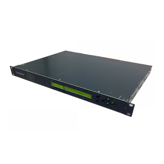
RS-232/RS-485 Port ........1-13 [Option] ............1-6 Network ............1-13 TANDBERGTV G.703 Input (Telco Receivers) [Option] ........1-6 1.5.4 TANDBERG Director NCP Control Mode..1-13 ATM AAL-1 DS3 Input (Telco Receivers) 1.6 Guided Tour.............1-14 [Option] ............1-6 1.6.1 Construction ..........1-14 ATM AAL-1 E3 Input (Telco Receivers) 1.6.2 Front Panel Controls ........1-14... - Page 10 List of Tables Table 1.1: Equipment Model Descriptions........1-3 List of Figures Figure 1.1: Front View of the TT1260..........1-3 Figure 1.2: Typical Satellite Compression System......1-9 Figure 1.3: What the Satellite Receiver Does ......1-10 Figure 1.4: Typical Download Transmission System ....1-10 Figure 1.5: Typical Compression System........1-11...
-
Page 11: Scope Of This Reference Guide
Who Should Use This Reference Guide This Reference Guide is written for operators/users of variants of the TT1260 Contribution Receiver and options. It describes the unit’s functions and operation. The Reference Guide is written to assist in the installation and day-to-day care and operation of the unit. Maintenance information requiring the covers to be removed is not included. -
Page 12: Summary Of Features
Introduction Summary of Features 1.2.1 Main Features The TT1260 is fully compliant with the appropriate sections of the MPEG-2 , DVB-S and DSNG specifications and offers the following features: · Front Panel Controls and Indications: ² A vertical split two line x 40 character back-lit dot matrix LCD... - Page 13 ² TANDBERG Television Signal Protection (option) ² DVB Common Interface (option) · TANDBERG Director system: ² Over-air remote control is available if the TT1260 is used as part of a TANDBERG Director system (Over-air software downloading, Re-start, Tuning and Retuning etc.) NOTES…...
-
Page 14: Inputs
ATM AAL-1 E3 Input (Telco Receivers) [Option] Equipped with two BNC connectors for receiving full-duplex signals over a PDH Telco network. IP Input [Option] An RJ-45 connector for receiving MPEG-2 signals over an Ethernet network. Page 1-6 Reference Guide: TT1260 Contribution Receiver ST.RE.E10100.1... -
Page 15: Remote Control
ALARM LED. There is a 25-way D-type connector on the Alarm Relay Card (TT1260/HDC/ALRM) with six relays for failure monitoring for NCP over-air. The operator can define (using the Alarm Menu pages) which alarm conditions drive the relays. This is described in Chapter 5, Alarms and Annex C, Menus. -
Page 16: Conditional Access And Scrambling
The Satellite Receiver 1.3.1 Typical Satellite System The TT1260 Satellite Receiver is a component of the MPEG-2/DVB compliant range of TANDBERG Television equipment. It is designed for use by broadcasters and distributors of video, audio and data services over satellite. -
Page 17: What The Satellite Receiver Does
Decoder circuit. The received channel may contain multiple services, therefore the Receiver’s demultiplexer is configured to select a single video service and other audio/data components and present them at the output. Reference Guide: TT1260 Contribution Receiver Page 1-9 ST.RE.E10100.1... -
Page 18: Over-Air Software Download (Tandberg Director Systems)
Over-air Software Download (TANDBERG Director Systems) The TT1260 Satellite Receiver is shipped with the appropriate software installed, but it is designed to allow replacement of this code by new versions of software transmitted over-air. The new code is downloaded as a background task in the same transport stream as used for the normal transmission of services. -
Page 19: The Telco Receiver/Decoder
1.4.1 Typical Decoder System The Decoder is a component of TANDBERG Television’s range of equipment. It is designed for use by broadcasters and distributors of video and audio services. It can be used as a transport stream monitor or to decode signals received over a telecommunications network. -
Page 20: What The Decoder Does
Receiver (dependent upon options fitted). The unit remains in the chosen control mode until another mode is requested. NOTE… Local (Front Panel) Control is the factory default if TANDBERG Director is not installed. Page 1-12 Reference Guide: TT1260 Contribution Receiver ST.RE.E10100.1... -
Page 21: Front Panel (Local) Modes
NCP control mode. NOTE… Front Panel mode is the factory default for Receivers used in a TANDBERG Director system. To switch to Director NCP mode refer to Section 3.9, Setting Up System Parameters. All Front Panel and Serial Remote commands are ignored except the operating mode. -
Page 22: Guided Tour
Bit Error Ratio Measurement Bit Error Ratio (BER) measurement is done by an LCD display representation. See the QPSK Satellite menu (Section C.5, Input Status Menu). E is also available in this way. Page 1-14 Reference Guide: TT1260 Contribution Receiver ST.RE.E10100.1... -
Page 23: Conditional Access And Scrambling Options
With the appropriate configuration, the TT1260 fully descrambles Signal Protection input transport streams. DVB Common Interface The TT1260 Common Interface version has a common interface (CI) slot at the rear. The CI module has to be inserted first, before a card can be inserted. - Page 24 Introduction BLANK Page 1-16 Reference Guide: TT1260 Contribution Receiver ST.RE.E10100.1...
- Page 25 General ............2-7 Figure 2.4: Typical Decoder Rear Panel ........2-10 Wire Colours ..........2-8 Figure 2.5: TT1260 Signal Connections ........2-11 2.5.2 Connecting the Equipment to the AC Figure 2.6: Typical Decoder Rear Panel, with ASI Input and Power Supply..........2-8 Alarm Option Fitted ............
- Page 26 Table 2.6: Analogue Output Connector ........2-13 Table 2.7: Digital Output Connector ..........2-13 Table 2.8: Frame Sync Hi-Z Connector........2-14 Table 2.9: Ethernet Pin-outs............2-14 Table 2.10: Remote Control Connector........2-15 Table 2.11: Alarm Connector............2-15 Table 2.12: RS-232 Low-speed Data Connector......2-16 Page 2-2 Reference Guide: TT1260 Contribution Receiver ST.RE.E10100.1...
-
Page 27: Read This First
Lightning Protection WARNING… IF THE TT1260 DECODER HAS BEEN SUBJECT TO A LIGHTNING STRIKE OR POWER SURGE WHICH HAS STOPPED IT WORKING, DISCONNECT THE POWER IMMEDIATELY. DO NOT REAPPLY POWER UNTIL IT HAS BEEN CHECKED FOR SAFETY. IF IN DOUBT, CONTACT TANDBERG TELEVISION CUSTOMER SERVICES. -
Page 28: Preliminary Checks
Mechanical Inspection WARNING… REMOVING THE COVERS OF THIS EQUIPMENT MAY INVAL DATE ANY WARRANTIES, CAUSE A SAFETY HAZARD OR/AND AFFECT THE EMC PERFORMANCE. CHECK WITH TANDBERG TELEVISION CUSTOMER SERVICES. Inspect the equipment for damage-in-transit. If in doubt, please contact TANDBERG Television Customer Services (see Preliminary Pages). -
Page 29: Installing The Equipment
2.3.1 Fixing The TT1260 is designed for fixed use only and has been shipped with fixing brackets suitable for a standard 19-inch rack. When installed in a rack, it should be secured using the fixing brackets. In addition, support shelves must be used to reduce the weight on the brackets. -
Page 30: Protection From Moisture
AC Supply Operating Voltage and Fusing - Safety Information The TT1260 operates from a wide-ranging mains power supply (100-120 Vac or 220-240 Vac 50/60 Hz nominal) and is designed for use in ambient air temperature in the range 0°C to +50°C. There are no links etc. -
Page 31: Ac Power Supply Cord
OVERLOAD WALL OUTLETS AND EXTENSION CORDS AS THIS CAN RESULT IN A RISK OF RE OR ELECTR C SHOCK. AC SUPPLY. THE TT1260 RANGE OF RECEIVERS AND DECODERS ARE NOT FITTED WITH AN AC POWER ON OFF SWITCH. ENSURE THE SUPPLY SOCKET OUTLET... -
Page 32: Wire Colours
As there is no mains power switch fitted to this unit, ensure the local ac power supply is switched OFF before connecting the supply cord. Connect the mains lead to the TT1260 and then to the local supply. -48 Vdc Power Supply 2.6.1... -
Page 33: Location Of The Dc Input Connector
Technical Earth terminal and a suitable point on the rack 2. Eliminate the migration of stray charges when connecting between equipment. The Technical Earth provides a suitable connection between the TT1260 and the installation to give a low impedance path at normal operating frequencies. -
Page 34: Signal Connections
Installing the Equipment Location of the Technical Earth Figure 2.3: Location of the Technical Earth Signal Connections 2.8.1 General CAUTION... It is strongly recommended that the terminal marked at the rear panel of the equipment is connected to a site Technical Earth before any external connections are made and the equipment is powered. This limits the migration of stray charges. - Page 35 COFDM nput Opt on Card (TT1260/COFDM678) COFDM In COFDM In 1 RS-422 Data Enabler Card (TT1260/HWO/HSDATA) DATA OUT High-speed Sync Data AC Mains Supply Power Supply Unit Figure 2.5: TT1260 Signal Connections Reference Guide: TT1260 Contribution Receiver Page 2-11 ST.RE.E10100.1...
-
Page 36: Tt1260 Base Unit (Tt1260/Dirbas)
Pin 3 ¾ Left + Pin 4 ¾ Right + Pin 5 ¾ Ground Pin 6 ¾ Digital audio - Pin 7 ¾ Ground Pin 8 ¾ Left - Pin 9 ¾ Right - Page 2-12 Reference Guide: TT1260 Contribution Receiver ST.RE.E10100.1... -
Page 37: Analogue Video Output
Section B.6.1, Video Outputs. SDI 1/2 Table 2.7: Digital Output Connector Item Specification Item Specification BNC 75 W socket Connector type Connector designation SDI 1 SDI 2 Pin-outs Centre Video output Shield Ground/Chassis Reference Guide: TT1260 Contribution Receiver Page 2-13 ST.RE.E10100.1... -
Page 38: Frame Synchronisation
Impedance Last unit must be terminated with 75 W 2.8.6 Ethernet/Web Browser/SNMP The TT1260 has an Ethernet remote control port for SNMP or XPO Control. This is also used for high-speed data over Ethernet output and TANDBERG engineering debug purposes. -
Page 39: Alarm Connector And Relay
#3.4. The technical specification for this connector is RS232 DATA given in Section B.6.3, Data Outputs. NOTE… Low-speed asynchronous data output is disabled when the High Speed RS-422 Data Enabler Card (TT1260/HWO/HSDATA) is fitted. Reference Guide: TT1260 Contribution Receiver Page 2-15 ST.RE.E10100.1... -
Page 40: Option Card Connectors
Pin 5 ¾ Ground Pin 6 ¾ Not used Pin 7 ¾ Not used Pin 8 ¾ Not used Pin 9 ¾ Not used Option Card Connectors Option cards are described in Chapter 6, Options. Page 2-16 Reference Guide: TT1260 Contribution Receiver ST.RE.E10100.1... - Page 41 (Menu #4.1)..........3-17 (TT1260/HWO/QPSK) ........3-7 3.8.3 TANDBERG Signal Protection (Menu QPSK/8PSK/16QAM Satellite Receiver #4.2) ............3-17 (TT1260/HWO/HM)........3-8 3.8.4 TANDBERG Director (Menu #4.3) ....3-17 QPSK/8PSK/16QAM Satellite Receiver 3.8.5 Basic Interoperable Scrambling System (TT1260/HWO/HOM) ........3-9 (BISS) (Menu #4.4) ........3-18 3.6.2 Terrestrial Receiver 3.8.6 DVB Common Interface (Menu #4).....3-18...
- Page 42 Table 3.29: System Restart Menu ..........3-22 Table 3.7: Setting Up the QPSK/8PSK/16QAM Satellite Receiver ................3-8 Table 3.30: Setting up a Preset Service ........3-22 Table 3.8: Setting Up the QPSK/8PSK/16QAM Satellite Page 3-2 Reference Guide: TT1260 Contribution Receiver ST.RE.E1O100.1...
-
Page 43: Powering The Equipment
Refer to Section 2.3.2 Ventilation. Connect the signal inputs and ac power supply to the TT1260 and power up the unit. After a short period of initialisation and the TT1260 gaining lock, the unit powers up in Navigate mode. This is the usual operating condition. -
Page 44: Front Panel Controls And Pushbuttons
Edit Mode Edit mode edits the right display area and allows the user to alter control parameters that define the TT1260 behaviour. To enter Edit mode press the Edit pushbutton when on a page containing an editable control parameter and the front panel is the controlling user interface. Edit may be entered on some special pages at all times, for example on the page defining the controlling user interface. - Page 45 Left pushbutton LED is lit it indicates there are additional editable parameters to the left of the current cursor position. There is a maximum idle period of five minutes when Edit mode times out and returns to Navigate mode. Reference Guide: TT1260 Contribution Receiver Page 3-5 ST.RE.E10100.1...
-
Page 46: Using The Local Controls
Each pushbutton has a built-in LED that turns on if the pushbutton the cursor to the required digit. function is appropriate to the displayed information. Change the value by using the arrow pushbuttons. Press Save to store the option. Page 3-6 Reference Guide: TT1260 Contribution Receiver ST.RE.E10100.1... -
Page 47: Setting Up Preset Services (Menu #1)
Using Preset Services This group allows up to 40 Services to be stored as presets. Selecting a Service from the preset list in Menu #1 automatically reconfigures the TT1260 to receive that Service with its associated parameters set as stored. 3.5.2 Setting Up a Preset Service Follow the steps in Table 3.5 to store the current Service as a preset. -
Page 48: Qpsk/8Psk/16Qam Satellite Receiver (Tt1260/Hwo/Hm)
This sets up the centre frequency Search Range for the selected SEARCH RANGE then press Save. Source in kHz. Scroll down to Menu #2.2 and select SOURCE 2. Repeat steps 2 through 8. Page 3-8 Reference Guide: TT1260 Contribution Receiver ST.RE.E10100.1... -
Page 49: Qpsk/8Psk/16Qam Satellite Receiver (Tt1260/Hwo/Hom)
This sets up the centre frequency Search Range for the selected SEARCH RANGE then press Save. Source in kHz. Scroll down to Menu #2.2 and select SOURCE 2. Repeat steps 2 through 10. Reference Guide: TT1260 Contribution Receiver Page 3-9 ST.RE.E10100.1... -
Page 50: Terrestrial Receiver (Tt1260/Hwo/Cofdm678)
Return to Input Menu # 2, it should display the current status. If status is NOT LOCKED, verify that the cable is properly connected and that all values have been entered correctly. Page 3-10 Reference Guide: TT1260 Contribution Receiver ST.RE.E10100.1... -
Page 51: 10/100Baset Ip (Tt1260/Hwo/Ip)
Set the required parameter, then press Save. Return to Input Menu #2, it should display the current status. If status is NOT LOCKED, verify that the cable is properly connected and that all values have been entered correctly. Reference Guide: TT1260 Contribution Receiver Page 3-11 ST.RE.E10100.1... -
Page 52: Service Configuration (Menu #3)
Edits the parameter for setting the video monitor aspect ratio parameter for setting the video monitor aspect and video output level. ratio (4:3, 16:9) and video output level (70 – 130%). Press Save.. Page 3-12 Reference Guide: TT1260 Contribution Receiver ST.RE.E10100.1... -
Page 53: Selecting The Audio Component
Edits the AC-3 downmix parameter. AC-3 downmix parameter (SURROUND STEREO or CONVENTIONAL STEREO) Press Save. Go to the Menu #3.3 for Audio 2 and repeat Selects the audio component. steps 2 through 5. Reference Guide: TT1260 Contribution Receiver Page 3-13 ST.RE.E10100.1... -
Page 54: Setting Up Asynchronous Data (Rs-232)
If it is not installed the unit will recover low speed data (see Section 3.7.4 The unit can recover either low speed (RS-232) data or high speed (RS-422) data but not both simultaneously. Page 3-14 Reference Guide: TT1260 Contribution Receiver ST.RE.E10100.1... -
Page 55: Setting Up Teletext
3.7.8 Setting Up the Vertical Blanking Interval (VBI) The TT1260 is compliant with EN 300 472 and DVB TM 2304 for all the VBI formats stated in Table 3.20. The TT1260 can handle VBI data transmitted as PES packets. It uses its own PID to extract the VBI PES packets from the transport stream. -
Page 56: Setting The Pcr Pid Menu
PCR PID. 3.7.10 Viewing the Network ID Menu Table 3.22: Viewing the Network ID Menu Step Action Result Go to Menu 3.9. Gains access to the Network ID and the Original Network ID. Page 3-16 Reference Guide: TT1260 Contribution Receiver ST.RE.E10100.1... -
Page 57: Setting Up The Conditional Access/Scrambling (Menu #4)
Menu #4.2 allows this protection system to be enabled/disabled. 3.8.4 TANDBERG Director (Menu #4.3) There is a single slot on the TT1260 rear panel to allow the insertion of a Smart Card for the TANDBERG Director system. The TANDBERG Director system offers premium functionality including Conditional Access, Over-Air software download and Over-Air Control. -
Page 58: Basic Interoperable Scrambling System (Biss) (Menu #4.4)
Conditional Access (CA) card for the CA system. The CAM and the CA card needs to be manufactured to host the same CA system. Please contact TANDBERG Television sales desk for the recommended CAM. Table 3.23: Setting Up the Conditional Access... -
Page 59: Setting Up The Transport Stream Output
ASI Output Mode · Spread mode in = > spread mode out (except when the TSO is set to DECRYPTED in step 2 in Table 3.24. Then the output is always bursted). Reference Guide: TT1260 Contribution Receiver Page 3-19 ST.RE.E10100.1... - Page 60 RELAY 5 ONLY, or SET RELAY 6 ONLY). Press Save. NOTE… This menu is only available with TT1260 Receivers. Decoders will supply the Transport Stream alarm first. Scroll down to Menu #5.2 and edit the Edits the Transport Stream alarms menu.
- Page 61 Displays the Firmware Version. Scroll down to Menu #6.2.2. Displays the Hardware Version. Scroll down to Menu #6.2.3. Displays the PLD Version. Scroll down to Menu #6.2.4. Displays the Electronic Serial Number. Reference Guide: TT1260 Contribution Receiver Page 3-21 ST.RE.E10100.1...
-
Page 62: Restarting The Unit
1. NOTE… It is not possible to store a service to a preset unless that service is being received (including all the required components such as video, audio, data, VBI, etc). Page 3-22 Reference Guide: TT1260 Contribution Receiver ST.RE.E10100.1... - Page 63 Overview............4-4 OAC Lockout ..........4-4 Entering the OAC Lockout PIN ..... 4-5 4.1.6 Remote Control using a Web Browser ..4-5 4.2 Returning the Unit to Local Control Mode ....4-5 Reference Guide: TT1260 Contribution Receiver Page 4-1 ST.RE.E10100.1...
- Page 64 Operating the Equipment Remotely BLANK Page 4-2 Reference Guide: TT1260 Contribution Receiver ST.RE.E10100.1...
-
Page 65: Remote Control
TANDBERG Director (over-air) · Web Browser Common for all control methods is that the TT1260 needs to be set up to accept the remote control handling. Once in remote control mode, it cannot be locally controlled unless the remote control is deactivated. -
Page 66: Configuring The Unit For Remote Control Via The Serial Remote Port
Configuring the Unit For Remote Control Over-air Overview For the unit to be controlled via over-air control (OAC), the control mode of the TT1260 needs to be set to Director NCP. Table 4.3: Activating Director NCP Remote Control Step Action Result Go to menu #6.1 SYSTEM SETUP menu... -
Page 67: Entering The Oac Lockout Pin
Operating the Equipment Remotely CAUTION… TANDBERG Television Customer Services Help Desk will not be able to provide you with the Local lockout PIN, as it is uniquely created at the time of the lockout. The user creates the PIN at lockout time. To obtain the PIN, please consult the person responsible for the administration of the unit. - Page 68 Operating the Equipment Remotely BLANK Page 4-6 Reference Guide: TT1260 Contribution Receiver ST.RE.E10100.1...
- Page 69 Contents List of Figures 5.1 Introduction ............... 5-3 Figure 5.1: Front Panel LEDs ............5-3 5.2 Location of the Alarm and Lock LEDs....... 5-3 5.3 ALARM LED and Summary Relay ......5-3 Reference Guide: TT1260 Contribution Receiver Page 5-1 ST.RE.E10100.1...
- Page 70 Alarms BLANK Page 5-2 Reference Guide: TT1260 Contribution Receiver ST.RE.E10100.1...
- Page 71 Alarms Introduction There are two Front Panel LEDs that indicate the status of the TT1260. There is also one summary alarm relay and six additional alarm relays (optional). These are used to indicate abnormal performance of the unit. Location of the Alarm and Lock LEDs The red ALARM LED is used to indicate an equipment fault condition, for example a missing or faulty input signal.
- Page 72 It is possible to signal additional alarms depending on the Transport Stream input type and optional functionality in the unit. Satellite inputs: · Bit Error Rate (BER) above (programmable) threshold. · Modulation Error Ratio (MER) above (programmable) threshold. Page 5-4 Reference Guide: TT1260 Contribution Receiver ST.RE.E10100.1...
- Page 73 6.2 Hardware Enabled Options ........6-4 6.4.1 RAS Mode 1 Conditional Access 6.2.1 ASI Input (TT1260/HWO/ASI)....... 6-4 (TT1260/SWO/RAS) ........6-8 6.2.2 QPSK Input Card (TT1260/HWO/QPSK) ..6-4 6.4.2 RAS Mode 2 Conditional Access General ............6-4 (TT1260/SWO/RAS2) ........6-8 Connector Details - L-Band Inputs....6-4 6.4.3 BISS-1 and BISS-2 (TT1260/SWO/BISS)..6-8...
- Page 74 Options BLANK Page 6-2 Reference Guide: TT1260 Contribution Receiver ST.RE.E10100.1...
-
Page 75: Available Options
Allows only 4:2:0 operation TT1260/SWO/LSYM Software key enabling low symbol-rate operation TT1260/SWO/SNMP Enable SNMP protocol for use with TANDBERG TDC and nCompass control systems. Requires software key licence option, see Table 6.2. Reference Guide: TT1260 Contribution Receiver Page 6-3 ST.RE.E10100.1... -
Page 76: Conditional Access
Options 6.1.3 Conditional Access The transport stream received by the TT1260 may be encrypted. The CA system is used to decrypt the required components of the transport stream so that they can be decoded. At Release 4.0.0, the receiver supports either DVB Common Interface or Smart Card based CA. These are selectable on ordering. -
Page 77: 16Qam/8Psk Input Card (Tt1260/Hwo/Hm)
The COFDM digital terrestrial input card demodulates COFDM signals. The board is able to be used in all RF channel bandwidths (6, 7 and 8 MHz). 6.2.5 TTV G.703 Input Card (TT1260/HWO/G703) The TTV G.703 input card receives a transport stream directly from a PDH network. -
Page 78: Ip Input Card (Tt1280/Hwo/Ip)
TS-packets are mapped in a datagram, using User Data Protocol (UDP), Internet Protocol (IP) and Ethernet. … TS packets (1 to 7) UDP datagram Information IP datagram 20 H Information Ethernet frame Information Figure 6.2: Building the Ethernet Frame Page 6-6 Reference Guide: TT1260 Contribution Receiver ST.RE.E10100.1... -
Page 79: Atm Aal-1 E3 Telco Input (Tt1260/Hwo/Atm-E3)
This card provides a complete digital front-end board for DVB-S, DSNG and other contribution applications and support 4 L-band inputs The HOM card provides a method of receiving new code via the TT1260’s debug interface, this takes the form of an FTP download into the TT1260. -
Page 80: High Speed Data Over Ethernet (Tt1260/Swo/Hsether)
6.3.6 Low Symbol-rate Operation (TT1260/SWO/LSYM) Software key enabling low symbol-rate operation. 6.3.7 SNMP Enabling (TT1260/SWO/SNMP) Enable SNMP protocol for use with TANDBERG TDC and nCompass control systems. Conditional Access 6.4.1 RAS Mode 1 Conditional Access (TT1260/SWO/RAS) This option enables RAS Mode 1 conditional access descrambling. - Page 81 7.5 Changing the Equipment Fuse........7-6 7.5.1 AC User Accessible Fuse Replacement ..7-6 7.5.2 DC User Accessible Fuse Replacement..7-7 7.6 Disposal ..............7-8 7.6.1 Moulded Plugs ..........7-8 7.6.2 Equipment............. 7-8 Reference Guide: TT1260 Contribution Receiver Page 7-1 ST.RE.E10100.1...
- Page 82 Preventive Maintenance and Fault-finding BLANK Page 7-2 Reference Guide: TT1260 Contribution Receiver ST.RE.E10100.1...
-
Page 83: Routine Checks
DO NOT ATTEMPT TO SERVICE THIS PRODUCT AS OPENING OR REMOVING COVERS MAY EXPOSE DANGEROUS VOLTAGES OR OTHER HAZARDS. REFER ALL SERVICING TO SERVICE PERSONNEL WHO HAVE BEEN AUTHORISED BY TANDBERG TELEVISION. The following is a list of conditions that may indicate the need for servicing: 1. -
Page 84: Replacement Parts
There is a customer service centre open round the clock, every day of the year, in your time zone. TANDBERG’s years of design and support experience enable it to offer a range of service options that will meet your needs at a price that makes sense. -
Page 85: Fault-Finding
CAUTION… Be sure to set the correct format and address via the front panel before attempting to use this input. The TT1260 will ignore any remote control commands if the input is not correctly set. Reference Guide: TT1260 Contribution Receiver Page 7-5 ST.RE.E10100.1... -
Page 86: Changing The Equipment Fuse
Technical Specification for details). There are no links or switches to be altered for operation from different ac supplies. The TT1260 is designed for User Accessible Fuse Replacement. In addition to the fuse in the supply cable plug (if appropriate) there is a fuse held in an integral fuse carrier at the ac power inlet at the rear of the unit. -
Page 87: Dc User Accessible Fuse Replacement
To access the fuse, ease out the notch with a small flat-blade screwdriver. Figure 7.2: Fuse Carrier If the replacement fuse also blows, do not continue. Disconnect the equipment and contact TANDBERG Customer Services (see Preliminary Pages) for advice. 7.5.2 DC User Accessible Fuse Replacement WARNING…... -
Page 88: Disposal
FE AS L VE ENDS MAY BE EXPOSED IF THE REMOVED PLUG IS INSERTED INTO A MAINS OUTLET. 7.6.2 Equipment Dispose of this equipment safely at the end of its life. Local codes and/or environmental restrictions may affect its disposal. Check with your local authority. Page 7-8 Reference Guide: TT1260 Contribution Receiver ST.RE.E1010.1... - Page 89 The following list covers most of the abbreviations, acronyms and terms used in TANDBERG Television Limited Manuals. All terms may not be included in this manual. Micrometre (former name - micron): a unit of length equal to one millionth (10 ) of a metre.
- Page 90 A TV picture subtitling system used with 525-line analogue transmissions. CODE Create Once Distribute Everywhere. Codec The combination of an Encoder and a complementary Decoder located respectively at the input and output of a transmission path. Page A-2 Reference Guide: TT1260 Contribution Receiver ST.RE.E10100.1...
- Page 91 (DVB-S), cable (DVB-C) and terrestrial (DVB-T) medium, created by the EP-DVB group and approved by the ITU. Specifies modulation, error correction, etc. (see EN 300 421 for satellite, EN 300 429 for cable and EN 300 744 for terrestrial). Reference Guide: TT1260 Contribution Receiver Page A-3 ST.RE.E10100.1...
- Page 92 Group of Pictures: MPEG video compression works more effectively by processing a number of video frames as a block. The TANDBERG Television Encoder normally uses a 12 frame GOP; every twelfth frame is an I frame. Graphical User Interface: The use of pictures rather than just words to represent the input and output of a program.
- Page 93 Low Noise Block Down-Converter: The component of a subscriber satellite transmission receiving dish which amplifies the incoming signal and down-converts it to a suitable frequency to input to the IRD (typically 950 MHz - 1600 MHz). Reference Guide: TT1260 Contribution Receiver Page A-5 ST.RE.E10100.1...
- Page 94 MCPC Multiple Channels Per Carrier. Multiplex Element Manager: A GUI based control system, part of the range of TANDBERG Television compression system control element products. The evolution 5000 MEM holds a model of the system hardware. Using this model, it controls the individual system elements to configure the output multiplexes from the incoming elementary streams.
- Page 95 A picture / frame produced using forward prediction. It contains predictions from either previous I frames or previous P frames. The P frame is used as a reference for future P or B frames. Parts per million. Reference Guide: TT1260 Contribution Receiver Page A-7 ST.RE.E10100.1...
- Page 96 Random Access Memory: A volatile storage device for digital data. Data may be written to, or read from, the device as often as required. When power is removed, the data it contains is lost. Remote Authorization System: A TANDBERG TV proprietary public-key encryption system used to prevent unauthorized viewing of a TV programme or programmes.
- Page 97 The data structure is defined in ISO/IEC 13818-1 [1] and is the basis of the ETSI Digital Video Broadcasting standards. Transport Stream Packet A data structure used to convey information about the transport stream payload. Header Transport Stream. Reference Guide: TT1260 Contribution Receiver Page A-9 ST.RE.E10100.1...
- Page 98 World System Teletext: System B Teletext. Used in 625 line / 50 Hz television systems (ITU-R 653). XILINX A type of programmable Integrated Circuit. Y (Luminance) Defines the brightness of a particular point on a TV line. The only signal required for black and white pictures. Page A-10 Reference Guide: TT1260 Contribution Receiver ST.RE.E10100.1...
-
Page 99: Technical Specification
Video Performance ........B-4 B.5.4 COFDM Terrestrial Receivers Vertical Blanking Signals ......B-4 (TT1260/HWO/COFDM678) ...... B-16 SDI..............B-5 B.5.5 TTV G.703 Input (TT1260/HWO/G703) ..B-17 B.5.6 ATM AAL-1 E3 Telco Input B.2 Audio Decoding and Output Stage......B-5 (TT1260/HWO/ATM-E3) ......B-18 B.2.1 General............B-5 B.5.7 ATM AAL-1 DS3 Telco Input B.2.2 MPEG Audio ..........B-6... - Page 100 Table B.38: Relay Alarm Output Specification (TT1260/HWO/ALARM) ..........B-24 Table B.7: Supported Audio Data Bit-rates (MPEG-2) ....B-8 Table B.39: Alarm Relay Card (TT1260/HWO/ALRM) Pin-outs .. B-24 Table B.8: Maximum User Bit-rates..........B-9 Table B.40: Environmental Conditions ........B-25 Table B.9: QPSK Satellite Receiver Input Specification ..... B-10 Table B.41: Physical Parameters ..........
-
Page 101: Output
The equipment supports decoding of non-encrypted compressed video at rates of up to 50 Mbit/s. B.1.3 Supported Video Resolutions The IRD supports 4:2:0 MP@HL and 4:2:2P@ML with video resolutions described in Table B.3. Reference Guide: TT1260 Contribution Receiver Page B-3 ST.RE.E10100.1... -
Page 102: Performance Figures
-55 dBrms Luminance freq. response 0-5 MHz: ±0.2 dB; 5.8 MHz: -2+0 dB Vertical Blanking Signals The TT1260 range of Receivers and Decoders support the following VBI reinsertion and signalling: · Video Programming System (VPS)/Programme Delivery Control (PDC) data and pass through ·... -
Page 103: Sdi
There is no requirement for specific selection behaviour where a service contains two or more audio components of the same coding type and language. The TT1260 is not required to support dynamic changes in the audio coding type once the initial selection has been made. Provision is made in the User Interface and remote interfaces for user override of default audio selection by language and audio coding type, or by PID. -
Page 104: Mpeg Audio
B.2.3 Dolby Digital AC-3 Audio The TT1260 is able to decode and output the primary stereo pair of a Dolby Digital AC-3 encoded audio stream. When there is data encoded on the audio surround channels, the Decoder applies downmixing, so that either a surround encoded stereo pair (LtRt downmix) or a conventional stereo pair (LoRo downmix) is available at the output. -
Page 105: Analogue Audio
Technical Specification B.3.2 Analogue Audio The TT1260 supports level control of the audio outputs. Independent control of each output of each stereo pair is provided via the User Interface and remote interfaces. Audio output connector type: 2 x 9 way female D-type Output level: +18 dBm nominal clipping level. -
Page 106: Audio Routing
Generic Coding of Moving Pictures and Associated Information: (MPEG-2) Audio. ATSC A-52 Digital Audio Compression Standard (Dolby Digital). SMPTE 302M Linear Audio (TANDBERG Television’s interpretation of the specification). B.3.8 Supported Audio Bit-rates Table B.7: Supported Audio Data Bit-rates (MPEG-2) Mono kbit/s... -
Page 107: Digital Audio Outputs
Audio output: balanced 2 – 7 volts. Internal Decoder The TT1260 contains an internal Decoder. A packet demultiplexer selects audio, video and ancillary services from the stream received from the digital demodulator. A service filter reduces the incoming data rate (max 160 Mbit/s) to that suitable for demuxing/decryption. -
Page 108: Input Option Specifications
EN 300 421: Digital broadcasting systems for television, sound and data services; Framing structure, channel coding and modulation for 11/12 GHz satellite services. These specifications apply in the presence of thermal noise at the threshold Eb/N ratio given in Table B.10. Page B-10 Reference Guide: TT1260 Contribution Receiver ST.RE.E10100.1... -
Page 109: Lnb Power And Control
Eb/No ratio is referred to user bit-rate Ru188. See EN 300 421 specification. For more detailed specification information and advice on performance in specific applications, please contact TANDBERG Television Customer Services. Table B.11: QPSK Bit-rate R188 Limits (Mbit/s) R188min R188max 1.000000... -
Page 110: 16Qam/8Psk Satellite Receivers
The displayed frequency is either L-band or SHF dependent on the LNB frequency and the SHF carrier frequency set in the satellite receiver input menu. Subject to minimum search range 0.1*Rs (QPSK, 16QAM), 0.05*Rs (8PSK) Page B-12 Reference Guide: TT1260 Contribution Receiver ST.RE.E10100.1... - Page 111 11/12 GHz satellite services. EN 301 210: Digital Video Broadcasting (DVB); Framing structure, channel coding and modulation for Digital Satellite News Gathering (DSNG) and other contribution applications by satellite. Reference Guide: TT1260 Contribution Receiver Page B-13 ST.RE.E10100.1...
-
Page 112: 16Qam/8Psk Lnb Control
Receive Polarisation: As specified in ETS 300 784: Satellite Earth Station and Systems (SES); Television Receive only (TVRO) earth stations operating in the 11/12 GHz frequency bands. These specifications apply in the presecence of thermal noise at the threshold Eb/no ratio given in Table B.16. Page B-14 Reference Guide: TT1260 Contribution Receiver ST.RE.E10100.1... -
Page 113: 16Qam/Qpsk Satellite Receivers (4-Input) (Tt1260/Hwo/H0M
+25 dBm min low gain Pin =-20 dBm +10 dBm min high gain Pin = -35 dBm Third-order intercept point 13dBm typical low gain Pin =-20 dBm -2dBm typical high gain Pin =-35dBm Reference Guide: TT1260 Contribution Receiver Page B-15 ST.RE.E10100.1... -
Page 114: Cofdm Terrestrial Receivers (Tt1260/Hwo/Cofdm678
Safety Status SELV 75 W Input connector Input level -20 to – 80 dBm Frequency range 48 – 860 MHz (depending on model) 6, 7 or 8 MHz depending on model Channel bandwidth Page B-16 Reference Guide: TT1260 Contribution Receiver ST.RE.E10100.1... -
Page 115: Ttv G.703 Input (Tt1260/Hwo/G703
Network Type Network Specification CCITT (ITU-T) G.703 Reed-Solomon On/Off, Not available in 188-packet mode De-Interleaver On/Off, Not available in 188-packet mode Status LED Green: Lock, Red: No Lock Output Connector Not in use Reference Guide: TT1260 Contribution Receiver Page B-17 ST.RE.E10100.1... -
Page 116: Atm Aal-1 E3 Telco Input
Technical Specification B.5.6 ATM AAL-1 E3 Telco Input (TT1260/HWO/ATM-E3) This provides reception of MPEG-2 transport stream packets (respectively RS coded MPEG-2 TS packets) over PDH links using ATM cells, this particular version uses E3 style PDH framing. This input is designed to be compliant with prETS 300813 DVB Interfaces to PDH Networks. -
Page 117: Dvb-Asi Input (Tt1260/Hwo/Asi
Data rate range 0.350 - 160 Mbit/s Error decoding None B.5.9 10/100BaseT IP Input (TT1260/HWO/IP) This allows transport streams to be piped to the TT1260 over an Ethernet network. Table B.27: 10/100BaseT IP Input Specifications Input Specification Safety status SELV... -
Page 118: Output Options
RJ-45 Ethernet port. This is enabled through the licence key (TT1280/SWO/HSETHER). The TT1260 extracts data from the MPEG-2 TS stream and output it in IP/Ethernet frames. The de-encapsulation complies with open encapsulation standards described in ETSI EN 301 192 v.1.2.1 (1999-06), and ATSC document A90 (26 July 00). -
Page 119: Frame Sync Connector
PAL – I, B, G, D PAL – N Combination PAL - N PAL - M NTSC-M (with and without pedestal) (set on Video Menu, #3.1) 1000 mV ± 30 mV video level (luminance) Reference Guide: TT1260 Contribution Receiver Page B-21 ST.RE.E10100.1... -
Page 120: Digital Video
SELV Connector type 9-Way D-type Connector designation RS232/RS422 DATA OUT Data-rates (bit/s) 1200; 2400; 4800; 9600; 19 200; 38 400 Standards EIA RS-232C / ITU-T BT. V.24/V.28 Line length < 15 metres Page B-22 Reference Guide: TT1260 Contribution Receiver ST.RE.E10100.1... -
Page 121: Rs-232/Rs-485 Remote Control Connector
Technical Specification NOTE… If the High-speed option (TT1260/HWO/HSDATA) is fitted, the Low-speed output is not available. B.8.4 RS-232/RS-485 Remote Control Connector Table B.35: RS232/485 Control Connector Item Specification Safety status SELV Connector type 9-way D-type, male Connector designation RCTRL RS-232/485... - Page 122 Technical Specification B.8.7 Alarm Connector (TT1260/HWO/ALRM) [Option] This is an optional card. Table B.38: Relay Alarm Output Specification (TT1260/HWO/ALARM) Item Specification Safety status SELV Connector type 25-way D-type female Connector designation: ALARM RELAY Contact Configuration SPDT (Change-over) All volt-free contacts, fully isolated.
- Page 123 Do not use reversible plugs with this equipment. Class of equipment Class I Equipment (EN 60950 para 1.2.4): electric shock protection by basic insulation and protective earth. Rated voltage 100-120/220-240 Vac (single phase) Reference Guide: TT1260 Contribution Receiver Page B-25 ST.RE.E10100.1...
- Page 124 45 W typical (NO options fitted) 180 W maximum B.10.2 DC Supply Input (-48 Vdc Version) NOTES... Only models TT1260/CIBAS/48 and TT1260/DIRBAS/48 use a DC power supply. Ensure correct polarity is maintained. The unit must have a protective earth. Table B.43: DC Power Supply Specification...
- Page 125 Technical Specification B.11 Cable Types The signal cable types (or similar) in Table B.44 are those recommended by TANDBERG Television in order to maintain product EMC compliance. Table B.44: Suitable Signal Cable Types Signal Type Connector Cable RS-232/RS-422 Data Out...
- Page 126 The CE mark was first affixed to this product in 2002. The EMC tests were performed with the Technical earth attached, and configured using recommended cables. Applies only to models of the Product using ac power sources. Page B-28 Reference Guide: TT1260 Contribution Receiver ST.RE.E10100.1...
- Page 127 The C-Tick mark is affixed to denote compliance with the Australian Radiocommunications (Compliance and Labelling – Incidental Emissions) Notice made under s.182 of Radiocommunications Act 1992. NOTE... The C-Tick mark was first affixed to this product in 2002. Reference Guide: TT1260 Contribution Receiver Page B-29 ST.RE.E10100.1...
- Page 128 Technical Specification BLANK Page B-30 Reference Guide: TT1260 Contribution Receiver ST.RE.E10100.1...
- Page 129 C.5.3 QPSK Satellite Option C.7.6 Satellite BER Alarm Setup Menu ....C-18 (TT1260/HWO/QPSK) ........C-6 C.7.7 MER Alarm Setup Menu ......C-19 C.5.4 ASI Input Option (TT1260/HWO/ASI) ...C-6 C.7.8 Satellite EBNO Alarm Setup Menu .... C-19 C.5.5 TTV G.703 Input Option (TT1260/HWO/G703) ........C-7 C.8 System Menu (Menu #6) ........
- Page 130 Table C.30: MER Alarm Setup Menu .......... C-19 Table C.31: EBNO Alarm Setup Menu........C-19 Table C.32: Setup Menu ............. C-20 Table C.33: IRD Details Menu............. C-21 Table C.34: System Restart Menu ..........C-21 Page C-2 Reference Guide: TT1260 Contribution Receiver ST.RE.E10100.1...
-
Page 131: Lcd Menus
Input Enters the Input menu. Service Enters the Service menu. C.5.6 The Conditional Access menu is not available in software version 1.0. Alarms Enters the Alarms menu. System Enters the System menu. Reference Guide: TT1260 Contribution Receiver Page C-3 ST.RE.E10100.1... -
Page 132: The Menu Structure
4.5 CA Provider Lock 3.7.8 ITS Insertion 4.6 CA Transport Stream Output 3.7.9 NTSC Pedestal Insertion 3.8 PCR Selection Dependen on model type. 3.9 Network ID/Original Network ID Figure C.1: Menu Structure Page C-4 Reference Guide: TT1260 Contribution Receiver ST.RE.E10100.1... -
Page 133: Presets Menu Items (Menu #1
The Input Selection menu allows the user to select the Transport Stream source. Table C.4: Input Selection Menu Display Title: Input Description Select XXXX XXXX is the editable input source selection (any option cards). Reference Guide: TT1260 Contribution Receiver Page C-5 ST.RE.E10100.1... -
Page 134: Qpsk Satellite Option
When a QPSK Input interface is used, the Input menu allows the user to edit the QPSK parameters. Table C.6: ASI IP Menu Display Title: Input Description Select Source X is the editable input source selection 1, 2 or auto. Select Source X Page C-6 Reference Guide: TT1260 Contribution Receiver ST.RE.E10100.1... -
Page 135: Ttv G.703 Input Option
Menus C.5.5 TTV G.703 Input Option (TT1260/HWO/G703) When a TTV G.703 input interface is used, the Input menu allows the user to edit the set-up parameters Table C.7: TTV G.703 Menu Display Title: Input Description STATUS PDH Rate XXXXX is the framing mode of the TTV G.703 input module (None, C-Bit, M13) -
Page 136: Atm Aal-1 E3 Input Option
Menus C.5.7 ATM AAL-1 E3 Input Option (TT1260/HW0/ATM-E3) When an ATM AAL-1 E3 input interface is used, the Input menu allows the user to edit the set-up parameters Table C.9: ATM AAL-1 E3 Input Menu Display Title: Input Description STATUS... -
Page 137: Cofdm Input Option
WW is the SPECTRUM SENSE (NORMAL, INVERTED or AUTO) LNB Power XX XX is the LNB POWER (ON, OFF or BOOSTED) LNB 22 kHz YY YY is ENABLE/DISABLE Search Range ZZ ZZ is the SEARCH Range in kHz Reference Guide: TT1260 Contribution Receiver Page C-9 ST.RE.E10100.1... -
Page 138: Service Menu (Menu #3
The Async Data submenu allow status monitoring and C.6.5 configuration of the low and high speed data. The High-speed sync option is only available when option TT1260/HWO/HSDATA is purchased. Low-speed data isnot available in this instance. Ethernet Data The Ethernet Data sub menu allows status monitoring and C.6.6... -
Page 139: Video Menu
YYYYYY is the editable NTSC framesync offset range –199999 to +199999 Framesync NTSC Offset YYYYYY pixels Monitor Aspect Ratio Output Level Embedded Audio DID Channel Start Line 525: Line 22/23 Enable/Disable EDH Active Format Descriptor Reference Guide: TT1260 Contribution Receiver Page C-11 ST.RE.E10100.1... -
Page 140: Audio 1 Menu
Clipping Level XX dB XX is the editable Audio 2 clipping value (12 – 24 dB) AC3 Downmix Method XXXXXXXXXXXXX is the editable Dolby Digital AC-3 downmix parameter (SURROUND STEREO, CONVENTIONAL STEREO) XXXXXXXXXXXXX Page C-12 Reference Guide: TT1260 Contribution Receiver ST.RE.E10100.1... -
Page 141: Async Data Menu
YYYY is the number of frames Lost Frame Lost Forward to Gateway XXX XXX is the editable Gateway option (ON, OFF) When XXX is set to ON, the destination Gateway can be set. Gateway YYY.YYY.YYY.YYY Reference Guide: TT1260 Contribution Receiver Page C-13 ST.RE.E10100.1... -
Page 142: Teletext
The PCR PID submenu displays the Program Clock Reference packet identifier and its status. Table C.22: PCR PID Menu Display Title: PCR PID Description PCR PID XXXX XXXX is the PCR PID YYYYYYYYYY is (PRESENT, NOT PRESENT) YYYYYYYYYY Page C-14 Reference Guide: TT1260 Contribution Receiver ST.RE.E10100.1... -
Page 143: C.6.11 Network Id Menu
XXXXX is the network ID from the current SDT (or ----- when SDT not available) Network ID XXXXX YYYYY is the original network ID from the current SDT (or ----- when SDT not Original Network ID YYYYY available) Reference Guide: TT1260 Contribution Receiver Page C-15 ST.RE.E10100.1... -
Page 144: Alarms Menu (Menu #5
SET ALARM AND RELAY 1 SET ALARM AND RELAY 2 SET ALARM AND RELAY 3 SET ALARM AND RELAY 4 SET RELAY 1 ONLY SET RELAY 2 ONLY SET RELAY 3 ONLY SET RELAY 4 ONLY Page C-16 Reference Guide: TT1260 Contribution Receiver ST.RE.E10100.1... - Page 145 SET ALARM AND RELAY 1 SET ALARM AND RELAY 2 SET ALARM AND RELAY 3 SET ALARM AND RELAY 4 SET RELAY 1 ONLY SET RELAY 2 ONLY SET RELAY 3 ONLY SET RELAY 4 ONLY Reference Guide: TT1260 Contribution Receiver Page C-17 ST.RE.E10100.1...
- Page 146 SET ALARM AND RELAY 1 SET ALARM AND RELAY 2 SET ALARM AND RELAY 3 SET ALARM AND RELAY 4 SET RELAY 1 ONLY SET RELAY 2 ONLY SET RELAY 3 ONLY SET RELAY 4 ONLY Page C-18 Reference Guide: TT1260 Contribution Receiver ST.RE.E10100.1...
-
Page 147: Mer Alarm Setup Menu
SET ALARM AND RELAY 1 SET ALARM AND RELAY 2 SET ALARM AND RELAY 3 SET ALARM AND RELAY 4 SET RELAY 1 ONLY SET RELAY 2 ONLY SET RELAY 3 ONLY SET RELAY 4 ONLY Reference Guide: TT1260 Contribution Receiver Page C-19 ST.RE.E10100.1... -
Page 148: System Menu (Menu #6
XXXXXXXX is the editable parameter for setting automatic service selection (ENABLED, DISABLED) XXXXXXXX SI Mode XXX is the editable parameter for SI detection (AUTO, ATSC, DVB) Customisation Key XXXXXXXXXXXXXXXXXXXXXX is the editable parameter for entering customisation keys XXXXXXXXXXXXXXXXXXXXXX Page C-20 Reference Guide: TT1260 Contribution Receiver ST.RE.E10100.1... -
Page 149: Ird Details Menu
Table C.34: System Restart Menu Display Title: System Restart Description Restart Software restart. Press Edit to cancel and Save to activate. Activate Reference Guide: TT1260 Contribution Receiver Page C-21 ST.RE.E10100.1... - Page 150 Menus BLANK Page C-22 Reference Guide: TT1260 Contribution Receiver ST.RE.E10100.1...
-
Page 151: Language Abbreviations
ARABIC JAPANESE BASA JAVANESE BENGALI KOREAN CHINESE MALAY CZECH NORWEGIAN DANISH PORTUGESE DUTCH ROMANIAN ENGLISH RUSSIAN FINNISH SPANISH FRENCH SWEDISH GERMAN THAI GREEK TURKISH GUJARATI URDU HEBREW VIETNAMESE HINDI HUNGARIAN ICELANDIC INDONESIAN Reference Guide: TT1260 Contribution Receiver Page D-1 ST.RE.E10100.1... - Page 152 AUDIO 3 AUDIO 4 AUDIO 5 AUDIO 6 AUDIO 7 AUDIO 8 AUDIO 9 AUDIO 10 AUDIO 11 AUDIO 12 AUDIO 13 AUDIO 14 AUDIO 15 AUDIO 16 International Standards Organisation. Page D-2 Reference Guide: TT1260 Contribution Receiver ST.RE.E10100.1...
- Page 153 Annex E Using the TT1260 with the TANDBERG Director System Contents E.1 Configuring the TT1260 for Use With Director ..E-3 E.1.1 Getting Started..........E-3 E.1.2 Using the TT1260 in the Over-air Mode ..E-3 E.2 Response to Over-air Commands......E-4 E.2.1 Scope of This Section........E-4 E.2.2 Display On-screen Display (OSD)
- Page 154 Using the TT1260 with the TANDBERG Director System BLANK Page E-2 Reference Guide: TT1260 Contribution Receiver ST.RE.E10100.1...
- Page 155 E.1.2 Using the TT1260 in the Over-air Mode This section describes the behaviour of the TT1260 when it is controlled over-air using the Receiver Control part of the Director PC GUI. It is assumed that the Receiver is entitled to receive Director commands.
- Page 156 Sets the Receiver power-up service. If the Emergency Channel has not been set, it is set to this service. If neither the Emergency nor Power-up Channel have been set, the TT1260 will be in an indeterminate state at power-up. NOTE...
- Page 157 Using the TT1260 with the TANDBERG Director System E.2.6 Force Service Selection Forces the Receiver to decode a different service or stored channel (which may require a retune). The command is generally used to hop between services. The Director system has to be informed of the frequency, FEC-rate and symbol-rate for each stream.
- Page 158 Using the TT1260 with the TANDBERG Director System BLANK Page E-6 Instruction Manual: TT1260 Standard Definition Professional Receiver/Decoder ST.TM.E10100.4...
-
Page 159: Factory Defaults
TIME OUT 2.5 Sec CHANNEL FREQUENCY 722.0 MHz 2.3.1 BAND PLAN NONE 2.3.2 CHANNEL SPACE 8 MHz HIERARCHY STREAM #2 Input REED- SOLOMON DISABLED TTV G.703 2.2.1 INTERLEAVER DISABLED 2.2.2 SIGNAL LEVEL NORMAL Reference Guide: TT1260 Contribution Receiver Page F-1 ST.RE.E10100.1... - Page 160 VITC 525 LINE 14 and 16 3.6.4 VITC 625 LINE 19 and 21 3.6.5 VIDEO INDEX ENABLED 3.6.6 AMOL 1 and 2 ENABLED 3.6.7 CLOSED CAPTION ENABLED 3.6.8 ITS INSERTION (CCIR) ENABLED PCR PID Page F-2 Reference Guide: TT1260 Contribution Receiver ST.RE.E10100.1...
- Page 161 SERIAL REMOTE CONTROL RS-232 TTV 6.1.3 IP ADDRESS 155.155.155.201 6.1.4 SUBNET MASK 255.255.255.000 6.1.6 SERVICE HUNT MODE ENABLED 6.1.7 CUSTOMISATION KEY UNAFFECTED SW VERSION/ FW VERSION/ HW VERSION/ UNAFFECTED PLD VERSION/ ELECTRONIC SERIAL NUMBER Reference Guide: TT1260 Contribution Receiver Page F-3 ST.RE.E10100.1...
- Page 162 Factory Defaults BLANK Page F-4 Reference Guide: TT1260 Contribution Receiver ST.RE.E10100.1...
Need help?
Do you have a question about the TT1260 and is the answer not in the manual?
Questions and answers