
Related Manuals for Falcon DOMINATOR PLUS G3860F


Summary of Contents for Falcon DOMINATOR PLUS G3860F
- Page 1 User, Installation and Servicing Instructions GAS FRYERS G3860F & G3865F Read these instructions before use. DATE PURCHASED: MODEL NUMBER: SERIAL NUMBER: DEALER: SERVICE PROVIDER: T101116 Rev No: 1 Published: 20/08/2024...
- Page 2 Dear Customer Thank you for choosing Falcon Foodservice Equipment. This manual can be downloaded from www.falconfoodservice.com or scan here: IMPORTANT: Please keep this manual for future reference. Falcon Foodservice Equipment HEAD OFFICE Wallace View, Hillfoots Road, Stirling. FK9 5PY. Scotland.
-
Page 3: Table Of Contents
CONTENTS SYMBOLS & LABELS ....................5 SAFETY GUIDANCE ....................6 GENERAL SAFETY ....................6 INSTALLATION SAFETY ..................7 ELECTRICAL SAFETY ................... 8 GAS SAFETY ......................8 FIRE SAFETY ......................8 MAINTENANCE SAFETY ..................10 APPLIANCE INFORMATION ................... 12 OPERATION AND CULINARY GUIDANCE ............13 G3860F COMPONENT PARTS. - Page 4 COMMISSIONING ....................31 CONVERSATION ....................32 GAS CONVERSION CHECK LIST ............... 32 10.0 SERVICING ......................33 10.1 CONTROL PANEL .................... 34 10.2 SAFETY THERMOSTAT ................... 35 10.3 PIEZO IGNITER AND SPARK ELECTRODE ............ 37 10.4 GAS VALVE ...................... 38 10.5 PILOT ASSEMBLY ....................
-
Page 5: Symbols & Labels
1.0 SYMBOLS & LABELS SCREWDRIVER SPANNER COOKING OIL GREASE WARNING SPARK IGNITION FLAME VIEWPORT ALLEN KEY IGNITER C SPANNER REMOVE DEVICE PLUG WARNING READ MANUAL FIRE RISK REMOVER ELECTRICITY... -
Page 6: Safety Guidance
2.0 SAFETY GUIDANCE 2.1 GENERAL SAFETY 2.1.1 These instructions are only valid if the country code appears on the appliance. If the code does not appear on the appliance, refer to the technical instructions for adapting the appliance to the conditions for use in that country. -
Page 7: Installation Safety
2.1.12 Training and Competence: To help ensure the safe use of this appliance there is a requirement for you to provide whatever information, instruction, training, and supervision as is necessary to ensure, so far as is reasonably practicable, the health and safety of all users. 2.1.13 For further help and information on training and competence we refer you to the Health &... -
Page 8: Electrical Safety
2.2.4 Put a documented system in place for periodic inspections, testing and maintenance of our gas/ electrical appliances. Check that the fixed electrical installation has been inspected and tested by a competent electrical contractor (e.g. NICEIC-approved or ECA member) as prescribed in BS7671, within the last 5 years. - Page 9 Operator Competency and Training 2.5.1 Ensure you are trained in the safe and proper use of the fryer and know how to turn it off and switch the power or gas off at the mains. 2.5.2 Ensure you are familiar with the kitchen fire safety procedures and the location and proper use of correct fire safety equipment.
-
Page 10: Maintenance Safety
2.5.10 Do not operate the fryer with no or low oil levels. 2.5.11 We do not recommend using Solid Fat with these fryers as control does not have a Fat Melt Cycle. 2.5.12 Regularly change your cooking oil. Use colour charts to check on oil quality. - Page 11 2.6.10 If the thermostats or capillaries are damaged, then do not turn the appliance on. Contact Falcon or you approved service provider to undertake the necessary repairs. 2.6.11 To obtain maximum performance from this unit regular servicing of the appliance should be undertaken to ensure correct operation, it is functioning as intended, and safe to use.
-
Page 12: Appliance Information
3.0 APPLIANCE INFORMATION This appliance has been CE-marked on the basis of compliance with the UKCA/ Product Safety and Metrology Regulations/Gas Appliance Regulations, Electrical/LVD and for the heat inputs, gas Electromagnetic Compatibility (EMC) Regulations/Directives pressures and voltages stated on the data plate. -
Page 13: Operation And Culinary Guidance
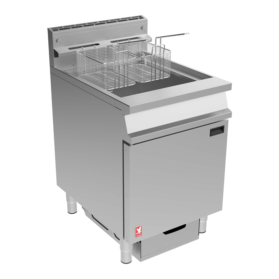
4.0 OPERATION AND CULINARY GUIDANCE 4.1 G3860F COMPONENT PARTS. Dust Cover Filtration Basket & Mesh Filter Basket Drain Valve Fry Plates Basket Hanger Crumb Catcher Oil Return Pipe Oil Bucket... -
Page 14: G3865F Component Parts
4.2 G3865F COMPONENT PARTS. Dust Cover Filtration Baskets & Mesh Filters Baskets Drain Valves Fry Plates Basket Hanger Crumb Catchers Oil Return Pipes Oil Buckets... -
Page 15: Controls
4.3 CONTROLS. Pump Switch Gas Control Safety Thermostat Reset Button Piezo Igniter Temperature Control... -
Page 16: Using The Appliance
4.4 USING THE APPLIANCE 4.4.1 Always clean the appliance before use. See section 5.0. PARTICULAR ATTENTION MUST BE PAID TO CLEANING THE THERMOSTAT BULB AND CAPILLARIES. ENSURING FOOD DEBRIS DOES NOT BUILD UP, WHICH COULD DETRIMENTALLY AFFECT THE PERFORMANCE AND SAFETY OF THE APPLIANCE. - Page 17 NEVER ALLOW OIL TO GO ABOVE MAX LEVEL WHEN UNLOADED AS THIS MAY CAUSE THE OIL TO OVERFLOW FROM THE PAN WHEN FOOD IS DROPPED IN. SUITABLE PROTECTIVE CLOTHING AND ALL CARE NECESSARY MUST BE USED WHEN TOPPING UP A HOT FRYER. IT IS RECOMMENDED THAT REPLENISHMENT OF THE OIL TAKES PLACE WHEN THE FRYER IS COOL.
- Page 18 4.4.6 When ready to cook, turn the gas control to the ON4 position. Set the temperature control5 as required between 140°C and 190°C. APPLIANCES THAT ARE IN USE MUST BE SUPERVISED AT ALL TIMES. OIL SHOULD NOT BE OVERHEATED AS THIS WILL INCREASE THE RISK OF FIRE FRYER IS FITTED WITH A THERMAL SAFETY DEVICE.
-
Page 19: Filtration
THE DRAIN VALVE MUST ONLY BE OPERATED WHEN THE GAS CONTROL IS SET TO OFF. NOT FOLLOWING THIS PART OF THE PROCEDURE WILL LEAD TO THE RESIDUAL OIL IN THE FRYER CATCHING FIRE. ENSURE OIL BUCKET IS IN POSITION. THE OIL BUCKET MAY BE HOT AND HEAVY WHEN FULL OF OIL. -
Page 20: Safety Reset
4.5.2 Ensure gas control is in the OFF 1 position and allow oil to cool for 15 to 20 minutes. Drain the oil into the oil buckets and switch on the filtration system using the pump switch 2. Let the oil cycle through the provided filtration basket and mesh filter to clear the debris within the oil. -
Page 21: Culinary Guidance
4.7 CULINARY GUIDANCE CARE MUST BE TAKEN WHEN INTRODUCING FROZEN OR WET PRODUCT INTO HOT OIL TO PREVENT SURGE BOILING. OLD OIL WILL HAVE A REDUCED FLASH-POINT AND BE PRONE TO SURGE BOILING. WATER MUST NEVER BE INTRODUCED INTO HOT OIL. OVERLOADING THE BASKETS WILL AFFECT THE FRYER PERFORMANCE. -
Page 22: Cleaning And Maintenance
• Fresh oil is best. Replace oil regularly, as old oil has a lower flash point which will lead to eventual surge boiling. • Using old oil further affects performance and adversely affects food quality, fry times and food output. •... - Page 23 BEFORE ANY CLEANING IS UNDERTAKEN, ISOLATE APPLIANCE FROM GAS SUPPLY AND MAINS POWER SUPPLY AT ISOLATOR SWITCH. SUITABLE PROTECTIVE CLOTHING MUST BE WORN WHEN CLEANING THIS APPLIANCE. NEVER PUMP WATER THROUGH THE FILTRATION PUMP AT ANY TIME. OIL MUST BE ALLOWED TO COOL TO A SAFE TEMPERATURE BEFORE DRAINING.
- Page 24 DAMAGE TO THE THERMOSTAT SENSORS OR THEIR CAPILLARIES CAN INCREASE THE RISK OF OVERHEATING OR FIRE. IF THE THERMOSTATS OR CAPILLARIES ARE DAMAGED THEN DO NOT TURN THE APPLIANCE ON. CONTACT FALCON OR YOU APPROVED SERVICE PROVIDER TO UNDERTAKE THE NECESSARY REPAIRS. SAFETY...
-
Page 25: Specification
6.0 SPECIFICATION 6.1 APPLIANCE WEIGHT TABLE APPLIANCE UNIT WEIGHT (kg) PACKED WEIGHT (kg) G3860F G3865F These fryer models have no heavy lift-off components. The oil buckets will be heavy when containing oil. 6.2 ELECTRICAL DATA TABLE CURRENT POWER MIN (A) @ MAX (A) @ ACTUAL (A) (kW) @... -
Page 26: Heat Input Table
6.4 HEAT INPUT TABLE HEAT INPUTS (NATURAL GAS AND PROPANE) APPLIANCE Btu/hr gross G3860F 112,600 G3865F 2 x 16.7 2 x 62,700 7.0 DIMENSIONS / CONNECTION LOCATIONS 7.1 G3860F FRYER. -
Page 27: G3865F Fryer
7.2 G3865F FRYER. 8.0 INSTALLATION Electrical Safety and Advice Regarding Supplementary Electrical Protection Commercial kitchens and foodservice areas are environments where electrical appliances may be located close to liquids, or operate in and around damp conditions, or where restricted movement for installation and service is evident. The installation and periodic inspection of the appliance should only be undertaken by a qualified, skilled and competent electrician;... -
Page 28: Siting / Clearances
8.1 SITING / CLEARANCES UNLESS OTHERWISE STATED, PARTS WHICH HAVE BEEN PROTECTED BY THE MANUFACTURER ARE NOT TO BE ADJUSTED BY THE INSTALLER. CAUTION: WALLS CLOSER THAN 150mm TO THE APPLIANCE MUST BE NON COMBUSTABLE. IF SUITING THE NECESSARY CLEARANCES TO ANY CUMBUSTIBLE WALL MUST BE THE LARGEST FIGURE GIVEN FOR INDIVIDUAL APPLIANCES INSTRUCTIONS. -
Page 29: Assembly
8.3 ASSEMBLY 8.3.1 Position the appliance and level using feet adjusters as shown below. TAKE CARE WHEN MOVING AN APPLIANCE FITTED WITH CASTORS. 8.3.2 Connect appliance to gas supply and test for gas tightness (see section 8.4) This appliance is also provided with a terminal for connection of an external equipotential conductor. -
Page 30: Gas Supply & Connection
8.4 GAS SUPPLY & CONNECTION 8.4.1 Installation pipe work should be fitted in accordance with local / national standards such as IGEM/UP/2. The pipework must not be smaller than unit gas inlet connection. If using flexible hosing, the hose must be sized to conform to BS 6173 and the length must not exceed 1.5m. -
Page 31: Commissioning
8.6 COMMISSIONING Refer to section 2.2 Installation Safety and 4.0 for operation. If safety thermostat is activated, refer to section 4.6 Safety Reset Carry out the following operation: 8.6.1 Turn the main gas supply on to the appliance. BURNER MANIFOLD PRESSURE TEST POINT 8.6.2 Connect a suitable pressure gauge to the pressure test point on the burner manifold... -
Page 32: Conversation
8.6.8 Switch appliance off. Disconnect pressure gauge and replace sealing screw and check for gas tightness. If the appliance does not operate correctly, please refer to section 10.0 and rectify the problem. PLEASE FILL OUT THE INFORMATION TABLE ON THE FRONT COVER AFTER COMMISSIONING. -
Page 33: Servicing
2. Serial number – found on data plate 3. Brief description of the issue To contact Falcon for a warranty issue dial (UK only) 01786 455 200 and select Warranty Issues from the menu. BEFORE ATTEMPTING ANY MAINTENANCE, ISOLATE THE APPLIANCE AT THE MAINS SWITCH AND TAKE STEPS TO ENSURE THAT IT IS NOT INADVERTENTLY SWITCHED ON. -
Page 34: Control Panel
10.1 CONTROL PANEL 10.1.1 Remove the control panel to gain access to the control components. WHEN RE-FITTING, MAKE SURE MAIN BURNER PIPE IS BENT TOWARDS THE REAR TO CREATE SPACE FOR SAFETY THERMOSTAT TERMINAL CONNECTIONS. -
Page 35: Safety Thermostat
10.2 SAFETY THERMOSTAT 10.2.1 To remove the safety thermostat – first step, remove cover panel then loosen phial capillary pan seal: SAFETY THERMOSTAT PAN SEAL... - Page 36 10.2.2 Second step, remove the sleeve nuts holding the phial cover then unclip the phial from the cover. Use a screwdriver to knock the sealing gland out within the pan boss to withdraw the phial from the pan. SAFETY THERMOSTAT PHIAL 10.2.3 When replacing the phial, apply an appropriate oil and temperature rated sealant on the pan sealing nut to fix it in place.
-
Page 37: Piezo Igniter And Spark Electrode
10.2.4 To remove safety thermostat body, remove spindle nut that secures thermostat to control panel: 10.3 PIEZO IGNITER AND SPARK ELECTRODE To remove piezo igniter, pull electrode and earth leads off at rear before removing fixing nut holding the igniter to the control panel. The spark electrode is attached to the pilot assembly. -
Page 38: Gas Valve
10.4 GAS VALVE 10.4.1 First step - remove cover panel then loosen phial capillary pan seal: GAS VALVE THERMOSTAT PAN SEAL... -
Page 39: Operating Thermostat Phial
10.4.2 Second step, remove the screws holding the operating thermostat phial cover then unclip the phial from the cover. Use a screwdriver to knock the sealing gland out to remove the phial. OPERATING THERMOSTAT PHIAL 10.4.3 When replacing the phial, apply an appropriate oil and temperature rated sealant on the pan sealing nut to fix it in place. - Page 40 10.4.4 To remove the gas valve from the gas pipework first undo main burner pipe compression fitting. Remove the 4 screws that hold the gas valve to bracket and bracket to appliance structure to allow valve to be pulled forward and give better access to rear pipework and thermocouple connections.
-
Page 41: Pilot Assembly
10.5 PILOT ASSEMBLY 10.5.1 Remove the fixings holding the pilot assembly to the underside of burner and drop the entire assembly including bracket down to gain access to fixing screws. BURNER PILOT ASSEMBLY 10.5.2 Pilot gas pipe/injector, thermocouple and electrode can now be removed. WHEN RE-FITTING THE PILOT ASSEMBLY, THE ELECTRODE CABLE AND THERMOCOUPLE MUST BE ROUTED ALONG THE PILOT PIPE AND NOT LOOPING INSIDE THE UNIT. -
Page 42: Burner
10.6 BURNER 10.6.1 Remove fixings that secure pilot and cross-lighter assemblies to main burner and drop the assemblies slightly. 10.6.2 Disconnect the compression joints above manifold. 10.6.3 Undo burner bracket fixings that retain burner assembly front cross strap to side runners. -
Page 43: Pump Switch
10.7 PUMP SWITCH 10.7.1 Remove the control panel as shown in 10.1. 10.7.2 Remove the wire from the pump switch noting their position. 10.7.3 Depress retaining clips and remove switch. -
Page 44: Pump
10.8 PUMP 10.8.1 Remove the rear access panel. electrical box cover. 10.8.2 Remove electrical box cover to gain access to the pump timer and electrical components. - Page 45 10.8.3 Disconnect the filtration flexi hose from the pump.
- Page 46 10.8.4 Disconnect the electrical coupling plug located inside the electrical box. 10.8.5 Remove the nut securing the pump capacitor. 10.8.6 Remove pump mounting bolts and lift pump clear taking the capacitor with it. 10.8.7 Replace pump in reverse order. 10.8.8 Check for leaks before replacing any panels. Note: The G3865F is fitted with two pumps.
-
Page 47: Pump Timer Setting
10.9 PUMP TIMER SETTING 10.9.1 Set top function to “0.8”. 10.9.2 Set middle function to “10” minutes 10.9.3 Set base function set to “Wu”. 10.10 GOVERNOR Natural Gas Appliance only – Adjust Governor as shown. 10.10.1 1 – Gas in 2 –... -
Page 48: Wiring Diagrams
10.11 WIRING DIAGRAMS 10.11.1 G3860F Circuit diagram. - Page 49 10.11.2 G3865F Circuit diagram.
- Page 50 10.11.3 G3860F Wiring diagram.
- Page 51 10.11.4 G3865F Wiring diagram.
-
Page 52: Accessories
11.0 ACCESSORIES 11.1 SPLASHGUARD 11.1.1 Remove basket hanger and place splashguard on top of the hob. Refit the basket hanger in front of the splashguard to secure them in place. -
Page 53: Fault Finding
12.0 FAULT FINDING FAULT POSSIBLE CAUSES REMEDY USER *ENG Burner/Pilot will not No gas to the unit. Check main gas is light/stay lit. turned on. Safety thermostat has Reset safety thermostat activated. as per section 2.5 If activates again call service engineer. -
Page 54: Spare Parts
13.0 SPARE PARTS PART DESCRIPTION Dust Cover Basket Fry Plate Crumb Catcher Basket Hanger Drain Tube Front Facia Door Assembly Piezo Igniter Safety Thermostat Gas Valve When ordering spare parts please quote the following: Model Number Serial number Gas type This information will be found on data plate attached to the appliance Visit our website for further spares information.
Need help?
Do you have a question about the DOMINATOR PLUS G3860F and is the answer not in the manual?
Questions and answers