Advertisement
Table of Contents
- 1 Table of Contents
- 2 Important Information
- 3 Installation
- 4 Assembly and Commissioning
- 5 Servicing
- 6 Spare Parts
- 7 Critical Dimensions
- 8 Operating Instructions
- 9 Changing/Filtering Oil
- 10 Cleaning and Maintenance
- 11 Preparation of Solid Fats/Oil
- 12 Cooking Hints
- 13 Wiring Diagrams
- 14 Wiring Diagrams
- 15 Circuit Diagrams
- 16 Circuit Diagrams
- Download this manual
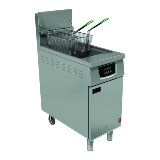
G401F/G402F FRYERS
INSTALLATION, SERVICING
and USER INSTRUCTIONS
These appliances must be installed and serviced by a qualified person as stipulated by the Gas Safety
(Installation & Use) Regulations.
IMPORTANT
The installer must ensure that the installation of the appliance is in conformity with these instructions
and National Regulations in force at the time of installation. Particular attention MUST be paid to -
Gas Safety (Installation & Use) Regulations I.E.E. Regulations for Electrical Installations
Health And Safety At Work etc. Act
Local and National Building Regulations
Fire Precautions Act
Detailed recommendations are contained in Institute of Gas Engineers published documents :
IGE/ UP/ 1, IGE/ UP/ 2, BS6173 and BS5440
These appliances have been CE-marked on the basis of compliance with the Gas Appliance Directive
for the Countries, Gas Types and Pressures as stated on the data plate.
WARNING -
TO PREVENT SHOCKS, ALL APPLIANCES, GAS OR ELECTRIC, MUST BE EARTHED.
On completion of the installation, these instructions should be left with the Engineer-in-Charge for
reference during servicing. Further to this, the user instructions should be handed over to the user,
having had a demonstration of the operation and cleaning of the appliance.
PREVENTATIVE MAINTENANCE CONTRACT
In order to obtain maximum performance from this unit we would recommend that a Maintenance
Contract be arranged with SERVICELINE. Visits may then be made at agreed intervals to carry out
adjustments and repairs. A quotation will be given upon request to the SERVICELINE contact
numbers below.
WEEE Directive Registration No. WEE/DC0059TT/PRO
At end of unit life, dispose of appliance and any replacement parts in a safe manner, via
a licenced waste handler. Units are designed to be dismantled easily and recycling of all
material is encouraged whenever practicable.
This equipment is ONLY FOR PROFESSIONAL USE, and shall be operated by QUALIFIED persons.
It is the responsibility of the supervisor or equivalent to ensure that users wear SUITABLE
PROTECTIVE CLOTHING and to draw attention to the fact that some parts will, by necessity, become
VERY HOT and will cause burns if touched accidentally.
Falcon Foodservice Equipment
HEAD OFFICE AND WORKS
Wallace View, Hillfoots Road, Stirling. FK9 5PY. Scotland.
SERVICELINE CONTACT
Phone: 01438 363 000
Fax: 01438 369 900
Electricity at Work Regulations
T100745 Ref. 9
Advertisement
Table of Contents

Related Manuals for Falcon G402F


Summary of Contents for Falcon G402F
- Page 1 G401F/G402F FRYERS INSTALLATION, SERVICING and USER INSTRUCTIONS These appliances must be installed and serviced by a qualified person as stipulated by the Gas Safety (Installation & Use) Regulations. IMPORTANT The installer must ensure that the installation of the appliance is in conformity with these instructions and National Regulations in force at the time of installation.
-
Page 2: Table Of Contents
IMPORTANT INFORMATION Warranty Policy Shortlist Warranty does not cover :- • Correcting faults caused by incorrect installation of a product. • Where an engineer cannot gain access to a site or a product. • Repeat commission visits. • Replacement of any parts where damage has been caused by misuse. •... -
Page 3: Installation
Model (mm) (mm) (mm) (kg) G401F Fryer 1200 1.3 VENTILATION G402F Fryer 1200 The appliance ventilation requirements requirements should be in line with national and local regulations. regulations. Pan oil capacity: The ventilation rate for these these models is 26m³/min. -
Page 4: Assembly And Commissioning
Ensure flexible cable does not come into contact with any hot parts. The fuse rating should be 13A. Rated Voltage Rated Current G401F/G402F 230V~ 3.55amps The colour coding of power supply cables are as follows: Live - Brown, Neutral - Blue, Earth - Green/Yellow THE APPLIANCE MUST BE EARTH BONDED. - Page 5 2.4.1 G401F Fryer Control Panel (See Figure 2) Figure 2 – G401F Control Panel 2.4.2 G402F Fryer Control Panel (See Figure 3) Figure 3 – G402F Control Panel 1. ON/OFF and Temperature Control Knob 1. Four Digit LED Display Temperature Selection (130 - 190°C). (Unit is off when control is in position indicated).
- Page 6 (Unit will only lock out after 2nd attempt). Figure 4 – G401F & G402F - Additional Additional Controls 8. The neon next to burner burner switch inside door will 3.
-
Page 7: Servicing
3.3 ACCESS PROCEDURES d) Turn burner and temperature controls ON/OFF switch to ON position. Before removal of any fryer components: e) Reselect temperature. a) Ensure appliance electrical and gas supply has been f) If limit thermostat reactivates carry out fault finding on shut off and cannot be accidentally turned back on. -
Page 8: Spare Parts
3.7 BURNER RESET SWITCH, ON/OFF SWITCH 3.12 FILTRATION PUMP and FILTRATION PUMP SWITCH a) Remove back panel and flexi-hose at filtration pump. a) Remove control panel by undoing fixings at top and b) Disconnect electrical coupling plug and connections bottom of control panel and unplug control panel. from start. -
Page 9: Critical Dimensions
Timer Timer Pump 24 min Settings Settings 26 max Set for 230V Operating thermostat probe Set to 0.8 Set to 10 minutes Safety thermostat probe Set to F Operating and Safety Thermostat Pilot to Burner Dimension Dimension... -
Page 10: Operating Instructions
Before operation, pan requires to be G401F - Manual control model with built-in filtration. thoroughly cleaned and dried. G402F - Four product key electronic control model Discolouration of heated parts is caused by factory with built-in filtration. - Page 11 See Section 6.3 for a worst case scenario, ignite the liquefied oils. instructions on how to display actual or set (ii) G402F only - Factory preset for a temperature of temperature). 180⁰C (See Section 6.3 for instructions on how to 4) Before carrying out any cooking operations, controller change set temperature).
- Page 12 Section 6.3). If temperature key is not pressed again 6.3.2 Programming a Product Cycle Time within 5 seconds, display returns to idle or timer mode. and Action Alarm a) Press and hold P key for 3 seconds. “Prog” will 6.3 PROGRAMMING THE G402F display. Note: Programming mode...
-
Page 13: Changing/Filtering Oil
OFF position before operation of filter pump SECTION 7 - can begin. CHANGING/FILTERING THE OIL 7.2 G401F and G402F MODELS Warning After filtering, wait 30 seconds before removing bucket. 1. Press filtration pump switch to turn on pump. -
Page 14: Cleaning And Maintenance
SECTION 8 - CLEANING and MAINTENANCE RECOMMENDATION 8.1 CLEANING THE APPLIANCE Personal protective equipment (PPE's) should be used 1) Carry out actions detailed in Sections 8 and 9. when cleaning or handling medium within this appliance. 2) Unit should be switched OFF and fry pot drained of oil. WARNING - NEVER PUMP WATER THROUGH THE 3) Remove baskets, fish plate and crumb catcher. -
Page 15: Preparation Of Solid Fats/Oil
SECTION 9 - PREPARATION OF SOLID FATS/SHORTENING WARNING: It is dangerous to use shortening that is too COOKING HINTS old. Such shortening has a reduced flash point Allow approximately 10 minutes for unit to heat up from temperature and is prone to surge boiling. cold to required operating temperature. -
Page 16: Wiring Diagrams
SECTION 11 – WIRING DIAGRAM for G401... - Page 17 SECTION 11 – WIRING DIAGRAM for G401F...
- Page 18 SECTION 11 – WIRING DIAGRAM for G402...
-
Page 19: Wiring Diagrams
SECTION 11 – WIRING DIAGRAM for G402F... -
Page 20: Circuit Diagrams
SECTION 11 – CIRCUIT DIAGRAM for G401... - Page 21 SECTION 11 – CIRCUIT DIAGRAM for G401F...
- Page 22 SECTION 11 – CIRCUIT DIAGRAM for G402...
-
Page 23: Circuit Diagrams
SECTION 11 – CIRCUIT DIAGRAM for G402F...
Need help?
Do you have a question about the G402F and is the answer not in the manual?
Questions and answers