Table of Contents
Advertisement
Quick Links
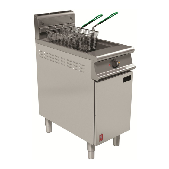
G3840/G3840X/G3840F/G3840FX
FRYERS
INSTALLATION, SERVICING and USER INSTRUCTIONS
CAUTION: Read the instructions before using the appliance
These appliances must be installed and serviced by a qualified person as stipulated by the Gas Safety
(Installation & Use) Regulations.
IMPORTANT
The installer must ensure that the installation of the appliance is in conformity with these instructions
and National Regulations in force at the time of installation. Particular attention MUST be paid to –
Gas safety (Installation & Use) regulations
Health & Safety at work, etc Act
Local and National Building Regulations
Detailed recommendations are contained in DW172 Institute of Gas Engineers published documents:
IGE/ UP/ 1, IGE/ UP/ 2, IGE/ UP/ 4, BS6173 and BS5440
These appliances have been UKCA/CE-marked based on compliance with the Gas Appliance
Regulations/Product Safety and Metrology Regulations, Electrical and Electromagnetic Compatibility
(EMC) Regulations/Directives for the Countries, Gas Types and Pressures as stated on the data plate
WARNING - TO PREVENT SHOCKS, ALL APPLIANCES, GAS OR ELECTRIC, MUST BE EARTHED.
On completion of the installation, these instructions should be left with the Engineer-in-Charge for
reference during servicing. Further to this, the user instructions should be handed over to the user,
having had a demonstration of the operation and cleaning of the appliance.
PREVENTATIVE MAINTENANCE CONTRACT
To obtain maximum performance from this unit regular servicing of the appliance should be undertaken to ensure
correct operation, it is functioning as intended, and safe to use. We recommend servicing in accordance with SFG20
Maintenance Schedules and as a minimum, after 2,500 hours of use, or annually, whichever comes first and that a
maintenance contract be arranged with an appointed service contact. Visits may then be made at agreed intervals
to carry out adjustments and repairs.
We recommend that the oil level sensor (
model should be serviced annually.
WEEE Directive Registration No. WEE/DC0059TT/PRO
At end of unit life, dispose of appliance and any replacement parts in a safe
manner, via a licenced waste handler. Units are designed to be dismantled
easily and recycling of all material is encouraged whenever practicable.
This equipment is ONLY FOR PROFESSIONAL USE, and shall be operated by QUALIFIED
persons. It is the responsibility of the supervisor or equivalent to ensure that users wear SUITABLE
PROTECTIVE CLOTHING and to draw attention to the fact that some parts will, by necessity,
become VERY HOT and will cause burns if touched accidentally.
Falcon Foodservice Equipment
Wallace View, Hillfoots Road, Stirling, FK9 5PY, Scotland
Phone: 01786 455200
I.E.E. Regulations for Electrical Installations
Electricity at Work Regulations
Fire precaution Act
UK Patent Serial No. GB2584184
)
in the G3840X/G3840FX
T100806 Ref.17
.
1
Advertisement
Table of Contents

Related Manuals for Falcon G3840


Summary of Contents for Falcon G3840
- Page 1 It is the responsibility of the supervisor or equivalent to ensure that users wear SUITABLE PROTECTIVE CLOTHING and to draw attention to the fact that some parts will, by necessity, become VERY HOT and will cause burns if touched accidentally. Falcon Foodservice Equipment Wallace View, Hillfoots Road, Stirling, FK9 5PY, Scotland Phone: 01786 455200...
- Page 2 IMPORTANT INFORMATION ELECTRICAL SAFETY AND ADVICE REGARDING SUPPLEMENTARY ELECTRICAL PROTECTION Commercial kitchens and foodservice areas are environments where electrical appliances may be located close to liquids, or operate in and around damp conditions or where restricted movement for installation and service is evident. The installation and periodic inspection of the appliance should only be undertaken by a qualified, skilled and competent electrician;...
- Page 3 Training and competence To help ensure the safe use of this appliance there is a requirement for you to provide whatever information, instruction, training and supervision as is necessary to ensure, so far as is reasonably practicable, the health and safety of all users. For further help and information on training and competence we would refer you the Health and Safety Executive website;...
-
Page 4: Table Of Contents
G3840/F Fryer Control Panel (See Figure 2) ................. 10 2.4.2 G3840X/G3840FX Fryer Control Panel (See Figure 3) ............11 2.4.3 G3840 & G3840F - Additional Controls - (See Figure 4) ............11 2.4.4 G3840 and G3840F Controller Diagnostic Indicators ............. 12 PRE-COMMISSIONING CHECK .......................... 12 2.5.1... - Page 5 PREPARATION OF SOLID FATS / SHORTENING ..................... 28 10.0 COOKING HINTS ..............................29 11.0 WIRING DIAGRAMS .............................. 30 11.1 G3840 WIRING DIAGRAM ..........................30 11.2 G3840X WIRING DIAGRAM ..........................31 11.3 G3840F WIRING DIAGRAM ..........................32 11.4 G3840FX WIRING DIAGRAM ..........................33 11.5...
-
Page 6: Installation
Discolouration of heated parts is caused by factory testing to ensure a satisfactory unit. It does not affect quality or performance. MODEL NUMBERS, NETT WEIGHTS & DIMENSIONS. Model Width (mm) Depth (mm) Height (mm) Weight (kg) G3840 Fryer 1090 G3840X Fryer 1090 G3840F Fryer 1090 G3840FX Fryer 1090 Pan oil capacity: 18 litres cold, good quality oil (to –MIN- mark) -
Page 7: Clearances
Installer must consult any additional local / national regulations. The fresh air requirement for this appliance at a rate of 2M³/hour per kW is 44 M³ is as follows: COMBUSTION AIR REQUIREMENTS APPLIANCE VENTILATION RATE G3840 44 m G3840X 44 m G3840F... -
Page 8: Electrical Supply
Supply pressure Burner pressure at manifold Natural Gas (I 20mbar 14mbar Propane Gas (I 37mbar 34mbar The incoming service must be of sufficient size to supply full rate without excessive pressure drop. A gas meter is connected to service pipe by gas supplier. Any existing meter should be checked preferably by gas supplier to ensure that it is adequate to deal with rate of gas supply required. -
Page 9: Total Rated Heat Inputs
Rated Voltage Rated Current G3840/G3840X/G3840F/G3840FX 230V~ 3.55amps TOTAL RATED HEAT INPUTS Appliance BTU/Hr (gross) Pilot G3840 / G3840X / G3840F / G3840FX *0.29kw 21.5kW 80,700 btu/h Nat (I *Ignites with main burners G3840 / G3840X / G3840F / G3840FX *0.26kw 22kW... -
Page 10: Connection To An Electrical Supply
Refer to Section 9. G3840X/G3840FX It is recommended that fat is pre-melted before pouring it in to the G3840X/G3840FX for the first time. G3840/F Fryer Control Panel (See Figure 2) Figure 2 – G3840 Control panel 1. ON/OFF and Temperature Control Knob Temperature Selection (140 - 190°C). -
Page 11: G3840X/G3840Fx Fryer Control Panel (See Figure 3)
Indicates when the oil has dropped to the same level as the temperature probe (approximately 80mm below MIN mark). G3840 & G3840F - Additional Controls - (See Figure 4) The following additional controls are located behind cabinet door. 1. Burner and Temperature Controls ON/OFF Switch Cuts power to burner and temperature controls. -
Page 12: G3840 And G3840F Controller Diagnostic Indicators
(Unit will only lock out after 2nd attempt). Neon next to burner switch inside door will illuminate to indicate lockout has occurred and that no burner flame is present. G3840 / G3840F Additional controls - Item 2 on Figure 4. Turn gas supply on. -
Page 13: Checking Controller Operation
If lockout should occur, repeat Steps 9 -10 until air is bled from supply and burner lights. When burner flame is established, check for gas leaks. Care should be taken because mains voltage is present. Isolate after gas checks. Checking Controller Operation To check operation of controls, refer to Using the Controller - Section 6.2.3. -
Page 14: Servicing And Conversion
2. Serial number – found on data plate 3. Brief description of the issue To contact Falcon for a warranty issue dial (UK only) 01786 455 200 and select Warranty Issues from the menu. BEFORE ATTEMPTING ANY SERVICING, TURN OFF GAS SHUTOFF VALVE AND ELECTRICAL SUPPLY. -
Page 15: Gas Conversion
Moving the fryer with hot or cold oil in fry pot can be dangerous. Scalding could occur. Spilled oil or fat on the kitchen floor could cause slipping accidents and any such deposit should be cleaned up straight away. To prevent any such hazard, caution must be observed when moving fryer. GAS CONVERSION (Natural to propane or propane to natural) This model is suitable for field conversion. -
Page 16: Burner
BURNER Remove pilot/igniter/sensor assembly as Section 3.5. Remove drain handle. Split incoming gas connection to manifold. Undo two middle mounting bolts and remove two front burner retention bolts and slide burner forward until it clears rear retention mountings. Carefully drop burner. Re-connect in reverse order. -
Page 17: Mains On And Heat Demand Neons
3.11 MAINS ON and HEAT DEMAND NEONS Remove control panel by undoing fixings at top and bottom of control panel. Disconnect control panel. Remove electrical connections from neon. Undo neon retention nut. Carefully replace in reverse order. 3.12 DRAIN VALVE a) Remove burner as detailed in Section 3.6 b) Ensure fry pot is empty. -
Page 18: Oil Level Sensor (G3840X/G3840Fx Only, Figure 5)
3.16 OIL LEVEL SENSOR (G3840X/G3840FX only, Figure 5) a) Ensure fry pot is empty b) Remove back panel. c) Disconnect oil sensor wires (blue & red BNC connectors) from the evaluation unit. d) Remove LH side panel. e) Remove control panel. f) Carefully feed oil sensor wires (blue &... -
Page 19: Spares
Figure 5 – Oil level sensor circuit components 4.0 SPARES When ordering spare parts, always quote appliance type and serial number. This information will be found on unit data plate, located inside the fryer door on LH leg support face. Operating Controller Operating Controller Knob Operating Controller Temperature Sensing Probe... -
Page 20: Critical Dimensions
5.0 CRITICAL DIMENSIONS thermi stor Figure 7 – Critical dimensions... -
Page 21: Operating Instructions
PARTS WHICH HAVE BEEN PROTECTED BY THE MANUFACTURER ARE NOT TO BE ADJUSTED BY THE USER. The fryers are of single pan type. G3840 - Manual control model. G3840X - Manual control model with oil level sensor. G3840F - Manual control model with inbuilt filtration. - Page 22 Cold Medium - when filling with cold medium (see Figure 7), DO NOT FILL MEDIUM PAST -MIN- LEVEL MARK (Maximum cold fill mark) also, for Solid Medium - See Section 9. -MIN- Level Mark: Medium should NEVER be allowed to drop below this mark. Should this occur, top up immediately or switch fryer OFF.
-
Page 23: Appliance Controls
Turn burner and temperature controls to ON position. Reselect temperature. If limit thermostat reactivates, an investigation to determine the reason must be carried out by a qualified technician. APPLIANCE CONTROLS Refer to Sections 2.4.1 and 2.4.2 for controls layout and description. LIGHTING and OPERATION Safety Precautions The installer must fit a gas shut-off valve in the gas pipe that supplies the unit. -
Page 24: Changing/Filtering The Oil
Warning Do not select any setting other than FMC when using solid fats as this will trip the Temperature Limit (safety) thermostat or in a worst case scenario, ignite the liquefied oils. Fat or oil temperature will then be governed by controller to desired set temperature, selected by user on the control knob. -
Page 25: G3840F Model
Please Note – Warning Do not handle filter components or adjacent surfaces when pump is operating. Components will remain hot for a period after filter. Allow cooling. Use of PPE's is recommended. Note: Burner and temperature controls ON/OFF switch must be in OFF position before operation of filter pump can begin. -
Page 26: Cleaning And Maintenance
8.0 CLEANING and MAINTENANCE BEFORE ANY CLEANING IS UNDERTAKEN, ISOLATE APPLIANCE FROM MAINS POWER SUPPLY AT ISOLATOR SWITCH. SUITABLE PROTECTIVE CLOTHING MUST BE WORN WHEN CLEANING THIS APPLIANCE. NEVER PUMP WATER THROUGH THE FILTRATION PUMP AT ANY TIME ! WATER AND HOT OIL ARE AN EXPLOSIVE MIXTURE. - Page 27 CAPILLARIES CAN INCREASE THE RISK OF OVERHEATING OR FIRE. IF THE THERMOSTATS OR CAPILLARIES ARE DAMAGED THEN DO NOT TURN THE APPLIANCE ON. CONTACT FALCON OR YOUR APPROVED SERVICE PROVIDER TO UNDERTAKE THE NECESSARY REPAIRS. Location of Safety and Operating Thermostat Probes Slide up the oil level sensor guard (G3840X/G3840FX only).
-
Page 28: Preparation Of Solid Fats / Shortening
Oil level sensor guard lowered for normal operation Remove oil bucket by pulling forward then upward. Use handles and lift oil bucket to sink. Pour away soiled water. Note – All spills onto this product and on the floor should be cleaned up immediately. Thoroughly wash, rinse and dry oil bucket and oil suction pipe. -
Page 29: Cooking Hints
Solid Fat G3840X/G3840FX Only – For first use it is recommended that the solid fat is pre-melted before being added to the fry pot. If solid fat is to be used, remove fish plate and cut fat into small pieces. Place 17kg in fry pot and pack it down. -
Page 30: Wiring Diagrams
11.0 WIRING DIAGRAMS 11.1 G3840 WIRING DIAGRAM... -
Page 31: G3840X Wiring Diagram
11.2 G3840X WIRING DIAGRAM... -
Page 32: G3840F Wiring Diagram
11.3 G3840F WIRING DIAGRAM... -
Page 33: G3840Fx Wiring Diagram
11.4 G3840FX WIRING DIAGRAM... -
Page 34: G3840 Circuit Diagram
11.5 G3840 CIRCUIT DIAGRAM... -
Page 35: G3840X Circuit Diagram
11.6 G3840X CIRCUIT DIAGRAM... -
Page 36: G3840F Circuit Diagram
11.7 G3840F CIRCUIT DIAGRAM... -
Page 37: G3840Fx Circuit Diagram
11.8 G3840FX CIRCUIT DIAGRAM...
Need help?
Do you have a question about the G3840 and is the answer not in the manual?
Questions and answers