Falcon F900 SERIES User, Installation And Servicing Instructions
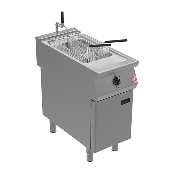
Electric single well fryer
Hide thumbs
Also See for F900 SERIES:
- User, installation and servicing instructions (58 pages) ,
- User, installation and servicing instructions (38 pages) ,
- User, installation and servicing instructions (26 pages)
Table of Contents


Need help?
Do you have a question about the F900 SERIES and is the answer not in the manual?
Questions and answers