
Related Manuals for Falcon Dominator Plus G3845


Summary of Contents for Falcon Dominator Plus G3845
- Page 1 User, installation and servicing instructions GAS TWIN PAN FRYER G3845, G3845F Read these instructions before use DATE PURCHASED: MODEL NUMBER: SERIAL NUMBER: DEALER: SERVICE PROVIDER: T101003 Rev No: 2 Published: 20/01/2019...
- Page 2 Dear Customer Thank you for choosing Falcon Foodservice Equipment. This manual can be downloaded from www.falconfoodservice.com or scan here: IMPORTANT: Please keep this manual for future reference. Falcon Foodservice Equipment HEAD OFFICE Wallace View, Hillfoots Road, Stirling. FK9 5PY. Scotland.
- Page 3 SYMBOLS SCREWDRIVER SPANNER COOKING OIL GREASE WARNING SPARK IGNITION FLAME VIEWPORT ALLEN KEY IGNITER C SPANNER REMOVE DEVICE PLUG REMOVER...
- Page 4 Ensure the supply cord is routed free from the appliance to avoid damage. The appliance has been designed and approved to use Falcon kick plates; non Falcon kick plates could potentially adversely affect the performance of the appliance by restricting the air to the appliance.
- Page 5 Training and competence To help ensure the safe use of this appliance there is a requirement for you to provide whatever information, instruction, training and supervision as is necessary to ensure, so far as is reasonably practicable, the health and safety of all users. For further help and information on training and competence we would refer you the Health and Safety Executive website;...
-
Page 6: Table Of Contents
CONTENTS 1.0 APPLIANCE INFORMATION ..................1 2.0 OPERATION ........................ 2 2.1 COMPONENT PARTS ..................... 2 2.2 CONTROLS ......................3 2.3 USING THE APPLIANCE ..................4 2.4 FILTRATION ......................7 2.5 SAFETY RESET ....................... 8 3.0 CLEANING AND MAINTENANCE ................9 4.0 ... - Page 7 8.11 PUMP ........................26 8.12 PUMP TIMER SETTING ..................27 8.13 CIRCUIT DIAGRAMS ..................28 8.14 WIRING DIAGRAMS ..................29 9.0 ACCESSORIES ......................30 9.1 SPLASHGUARD ....................30 10.0 FAULT FINDING ......................30 11.0 SPARE PARTS ......................32 12.0 SERVICE INFORMATION ..................33 ...
-
Page 8: Appliance Information
1.0 APPLIANCE INFORMATION This appliance has been CE-marked on the basis of compliance with the relevant EU directives for the heat inputs, gas pressures and voltages stated on the data plate. -
Page 9: Operation
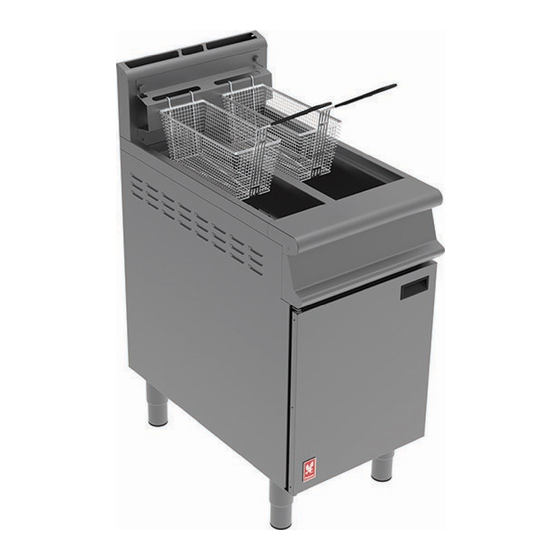
2.0 OPERATION 2.1 COMPONENT PARTS Dust Cover Oil Buckets (G3845F only) Baskets Filtration Basket & Mesh Filter Fry Plate (G3845F only) Crumb Catcher Oil Return Pipe Drain Pipe (G3845 only) Basket Hanger Drain Cleaning Rod (G3845F only) -
Page 10: Controls
2.2 CONTROLS Temperature Control Pump Switch (G3845F only) Piezo Igniter Safety Thermostat Reset Button Gas Control Drain Valve (G3845 Style) Drain Valve (G3845F Style) -
Page 11: Using The Appliance
2.3 USING THE APPLIANCE 2.3.1 The appliance must be as clean as possible before use as an appliance left with debris in or around its heating area can lead to fire. NEVER ADD COOKING OIL TO A FRYER WITHOUT ENSURING IT IS COMPLETELY DRY OF WATER. DOING SO CAN LEAD TO VERY HOT COOKING OIL BEING EJECTED FROM THE FRYER AS THE WATER UNDERNEATH IT BOILS AND EXPANDS INTO STEAM. - Page 12 2.3.3 Turn gas control to the LOW/LIGHT 1 position then push the button in as shown in the image below. 2.3.4 While still holding the gas control in the LOW/LIGHT 2 position, repeatedly press the piezo igniter 3 until the pilot burner lights. 2.3.5 Once the pilot flame can be seen 4, hold the gas control for a further 20 seconds 5 and when released the main burner will light at the LOW flame position.
- Page 13 2.3.8 To turn the burner off, turn the gas control to OFF position. 2.3.9 G3845 Draining – Draining old oil must be done after the oil has been allowed to cool. Ignoring this advice may lead to burns. Connect the supplied drain pipe onto the drain valve 1 as shown below.
-
Page 14: Filtration
2.4 FILTRATION 2.4.1 G3845F Only - Ensure gas control is in the OFF 1 position and allow oil to cool for 15 to 20 minutes. Drain the oil into the oil buckets and switch on the filtration system using the pump switch 2. Let the oil cycle through the provided filtration basket and mesh filter to clear the debris within the oil. -
Page 15: Safety Reset
2.5 SAFETY RESET 2.5.1 The safety thermostat is to prevent fire in the event of an operating thermostat failure and will prevent the main burners from working. If the burners don’t turn on, it may be due to the safety cut-out and the safety thermostat will need to be reset. 2.5.2 To reset the safety thermostat, first ensure the gas control is turned OFF and wait at least half an hour for the oil to cool. -
Page 16: Cleaning And Maintenance
3.0 CLEANING AND MAINTENANCE When removing heavy items to aid cleaning or maintenance particular care should be taken. A manual handling risk assessment is the best way to determine the level of risk to anyone using or maintaining this equipment. To help with such an evaluation we have included the weights of individual components that may present significant risk. - Page 17 It should be noted that certain scouring pads including nylon types can easily mark stainless steel. Care should be exercised during cleaning process. When rubbing stainless steel with a cloth, always rub in grain direction. 3.1.1 Turn appliance off and cool down. 3.1.2 Drain oil as stated in section 2.3.9 or 2.3.10.
-
Page 18: Specification
4.0 SPECIFICATION 4.1 APPLIANCE WEIGHT TABLE APPLIANCE UNIT WEIGHT (kg) PACKED WEIGHT (kg) G3845 G3845F 4.2 ELECTRICAL DATA TABLE CURRENT POWER MIN (A) @ MAX (A) @ ACTUAL (A) (kW) @ APPLIANCE PHASE 230V 230V @ 230V 230V G3845 G3845F 2.79 3.26 0.58... -
Page 19: Dimensions / Connection Locations
5.0 DIMENSIONS / CONNECTION LOCATIONS... -
Page 20: Installation
6.0 INSTALLATION Electrical Safety and Advice Regarding Supplementary Electrical Protection Commercial kitchens and foodservice areas are environments where electrical appliances may be located close to liquids, or operate in and around damp conditions, or where restricted movement for installation and service is evident. The installation and periodic inspection of the appliance should only be undertaken by a qualified, skilled and competent electrician;... -
Page 21: Ventilation
6.2 VENTILATION This appliance must be installed with sufficient ventilation to prevent the occurrence of unacceptable concentrations of substances harmful to health in the room in which they are installed. Installer must consult any additional local / national regulations. COMBUSTION AIR REQUIREMENTS APPLIANCE G3845 26 m... -
Page 22: Gas Supply & Connection
6.4 GAS SUPPLY & CONNECTION 6.4.1 Installation pipe work should be fitted in accordance with local / national standards. The pipe work must not be smaller than unit gas inlet connection. If using flexible hosing, the hose must be sized to conform to BS 6173 and the length must not exceed 1.5m. -
Page 23: Commissioning
6.6 COMMISSIONING Refer to section 2.0 for operation. If safety thermostat is activated, refer to section 2.5 to reset it. Carry out the following operation: 6.6.1 Turn the main gas supply on to the appliance. 6.6.2 Remove front facia as stated in section 8.1. Connect a suitable pressure gauge to the test points on the gas valve shown below and ensure the gas pressures are correct (see section 4.3 for gas pressures). -
Page 24: Conversion
7.0 CONVERSION BEFORE INSPECTION, SERVICING OR CONVERSION, TURN OFF GAS AT ISOLATOR. 7.1 GAS CONVERSION CHECK LIST Change injectors in burner(s) and pilots(s) (see 8.7 & 8.8). Change gas type label. For natural gas (G20) an appliance governor is required For Propane (G31) an appliance governor is not required 8.0 SERVICING BEFORE ATTEMPTING ANY MAINTENANCE, ISOLATE THE... -
Page 25: Front Fascia
8.1 FRONT FASCIA 8.1.1 Removal of the front fascia allows access to the pressure test points. 8.2 INNER CONTROL PANEL 8.2.1 Remove the inner control panel to gain access to the control parts. -
Page 26: Piezo Igniter, Safety Thermostat, Pump Switch
8.3 PIEZO IGNITER, SAFETY THERMOSTAT, PUMP SWITCH 8.3.1 To remove the safety thermostat phial, see section 8.5. 8.4 GAS VALVE 8.4.1 To gain access to the gas valve, remove the 4 screws that hold the gas valve bracket. The valve is secured to the bracket with nuts and screws. To remove the thermostat phial see section 8.6. -
Page 27: Safety Thermostat Phial
8.5 SAFETY THERMOSTAT PHIAL 8.5.1 To remove the phial, loosen the safety thermostat phial nut located behind the front fascia. 8.5.2 Remove the nuts holding the phial cover then unclip the phial form the cover. Use a screwdriver to knockout the graphite sealant to remove the phial. 8.5.3 When replacing the phial, apply an appropriate oil and temperature rated sealant on the nut to fix it in place. -
Page 28: Operating Thermostat Phial
8.6 OPERATING THERMOSTAT PHIAL 8.6.1 Remove the phial guard then unclip the phial out of its holder. Remove the two nuts to pull the phial out of the pan. 8.6.2 When replacing the phial, apply an appropriate oil and temperature rated sealant on the nut to fix it in place. -
Page 29: Pilot Assembly
8.7 PILOT ASSEMBLY 8.7.1 Remove the fixings holding the pilot mounting panel and drop the entire pilot assembly down to gain access to it. 8.7.2 Remove the pilot assembly from the mounting panel to access fittings easier for the pilot gas pipe, pilot injector, thermocouple and electrode. The pilot injector is removed using a 10mm spanner... -
Page 30: Burner
8.8 BURNER 8.8.1 Disconnect the compression fitting on both burners to remove the gas pipes. 8.8.2 Remove the fixings retaining the burner tray and slide the entire burner tray assembly out to gain access to the burner fittings. - Page 31 8.8.3 Now the burner injector can be accessed. Use a 13mm spanner to remove. 8.8.4 To remove burner from the burner tray, remove the two fixing screws at the front and remove the injector holder nut. Slide the burner out of the tray.
-
Page 32: Governor
8.9 GOVERNOR 8.9.1 Natural Gas Appliance only – Adjust Governor as shown. 1 – Gas in 2 – Gas out 3 – Direction of flow GOVERNOR SUPPLIED IS MAINTENANCE FREE. ENSURE THE BLUE DUST CAP COVERING THE VENT IS FITTED AND IN GOOD CONDITION. -
Page 33: Pump
8.10.2 G3845F only – Unplug 9 pin connector and push remaining part through electrical box. Remove two screws and lift electrical box away from unit. 8.11 PUMP 8.11.1 Remove pipe fixing on pump head. Remove the bottom pump access bracket by removing the two fixing screws. -
Page 34: Pump Timer Setting
8.11.2 From the front of the appliance, loosen the screws slightly that holds the pump. Remove the pump by lifting it out of the keyway and dropping it out of the appliance. 8.12 PUMP TIMER SETTING 8.12.1 Set top function to “0.8”. 8.12.2 Set middle function to “10”... -
Page 35: Circuit Diagrams
8.13 CIRCUIT DIAGRAMS 8.13.1 G3845F Circuit Diagram... -
Page 36: Wiring Diagrams
8.14 WIRING DIAGRAMS 8.14.1 G3845F Wiring Diagram... -
Page 37: Accessories
9.0 ACCESSORIES 9.1 SPLASHGUARD 9.1.1 Remove basket hanger and place splashguard on top of the hob. Refit the basket hanger in front of the splashguard to secure them in place. 10.0 FAULT FINDING FAULT POSSIBLE CAUSES REMEDY USER *ENG Burner/Pilot will not No gas to the unit. - Page 38 Pump not working. No electrical power to Check mains power is unit connected and turned Fuse has blown. Investigate and solve the cause then replace fuse at the rear of the unit. Pump overheating. Allow unit to cool for 15 minutes.
-
Page 39: Spare Parts
11.0 SPARE PARTS PART DESCRIPTION SPARES NUMBER Dust Cover 535620003 Basket 536430126 Fry Plate 535620002 Crumb Catcher 535620001 Basket Hanger 535620005 Drain Pipe 535710015 Oil Bucket 535620007 Fine Mesh Filter Wire Support 535580039 Fine Mesh Filter 535580038 Filter Basket 535580037 Oil Pick Up Pipe 535620006 Suction Pipe Filter... -
Page 40: Service Information
12.0 SERVICE INFORMATION It is recommended to have an annual maintenance contract with a local service provider. SERVICELINE CONTACT: (UK only) Phone: +441438 363 000 Warranty Policy Shortlist For our warranty policy please go to www.falconfoodservice.com...
Need help?
Do you have a question about the Dominator Plus G3845 and is the answer not in the manual?
Questions and answers