Table of Contents
Advertisement
Quick Links
S C A N F O R T H E
L A T E S T V E R S I O N
I N S T A L L A T I O N A N D O P E R A T I O N S M A N U A L
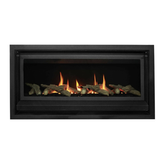
The Real Flame Inspire space heater is suitable to be installed into a frame out installation. Designed
to operate on Natural gas and LPG
Approval no. GMK 10528
Consumer safety information: please read this manual before installing and operating this appliance.
Failure to follow these instructions may result in a possible fire hazard and/or injury and will void the
warranty.
Ve rsi on 2
I N S P I R E M K 2 S P A C E H E A T E R
A L L F L U E C O N F I G U R A T I O N S
Advertisement
Table of Contents

Related Manuals for Real Flame INSPIRE MK2


Summary of Contents for Real Flame INSPIRE MK2
- Page 1 I N S T A L L A T I O N A N D O P E R A T I O N S M A N U A L The Real Flame Inspire space heater is suitable to be installed into a frame out installation. Designed to operate on Natural gas and LPG Approval no.
-
Page 2: Table Of Contents
C O N T E N T S WELC OME S PE CIFICAT IONS O P E R A T I O N I N S T R U C T I O N S USER INST R U C TIO NS TR OUB LESHO OT I NG F O R YO U R F I R EP LACE I N S T A L L A T I O N I N S T R U C T I O N S UNIT D IM ENSI ON S... -
Page 3: Welc Ome
W E L C O M E Congratulations on your selection of the elegant Real Flame Inspire fireplace. Enjoy mesmerising flame patterns in a truly efficient gas fireplace. Designed and developed in Australia for Australia, this fireplace is sure to be the centre piece of your home . Difference sizes for each design inspiration. We hope you create endless memories in front of this warm and cosy fireplace. - Page 4 I MP OR TAN T SA FE T Y NOT ICE Do not place articles on or against this appliance. Do not use or store flammable materials in or near this appliance. Do not spray aerosols in the vicinity of this appliance whilst it is in operation. Care must be taken to ensure that any return air register or exhaust system does not adversely affect the operation of the appliance or draught of chimney or flue.
-
Page 5: S Pe Cificat Ions
S P E C I F I C A T I O N S O F I N S P I R E 70 0 Appliance Type High Efficiency Gas Fireplace Star Rating Up to 4. 1 stars Maximum Heating Output Up to 5. - Page 6 S P E C I F I C A T I O N S O F I N S P I R E 9 0 0 Appliance Type High Efficiency Gas Fireplace Star Rating Up to 4. 1 stars Maximum Heating Output Up to 5.4 kW Heats Room up to approx.
- Page 7 S P E C I F I C A T I O N S O F I N S P I R E 110 0 Appliance Type High Efficiency Gas Fireplace Star Rating Up to 4.6 stars Maximum Heating Output Up to 6.9 kW Heats Room up to 100m...
-
Page 8: O P E R A T I O N I N S T R U C T I O N S
O P E R A T I O N I N S T R U C T I O N S Page... -
Page 9: User Inst R U C Tio Ns
U S E R I N S T R U C T I O N S • Do not operate if you smell gas. Turn appliance off, occur, turn off remote - wait 2 minutes before reattempting extinguish any open flame. Contact your installer or a to light the fire. - Page 10 AT T ENT I ON : REMOT E F LA ME C ON T RO L • Turn off the main gas supply of the appliance during The proflame has six (6) flame levels. With the system installation or maintenance of the receiver device. ON, and the flame level at the maximum in the appliance, pressing the down arrow key once will reduce the flame •...
- Page 11 C O N T I N U O U S P I LOT / I N T E R M I T T E N T P I LOT ( C P I / I P I ) S E L E C T I O N N OT E - Fire operation requires the system to be on IPI mode.
- Page 12 B AT T E RY P OW E R D E T E C T I O N T EAC HI NG RF C O DE – Rep ro grammi n g T R A N S M I T T E R re mo t e to hea te r (To be done by qualified personnel) The life span of the remote control batteries depends on...
-
Page 13: Tr Oub Lesho Ot I Ng F O R Yo U R F I R Ep Lace
• Turn off appliance and then have door seal inspected by service personnel or Real Flame agent. Room air fan is noisy or not working Faulty or dirty fan • Fan to be inspected and cleaned •... -
Page 14: I N S T A L L A T I O N I N S T R U C T I O N S
I N S T A L L A T I O N I N S T R U C T I O N S Page... -
Page 15: Unit D Im Ensi On S
U N I T D I M E N S I O N S UNIT INS700 1 12 INS9 00 1 12 INS1100 1084 1010 UNIT INS700 INS9 00 INS1100 1 105 Page... -
Page 16: Minimum Fr A Meou T Di Men S I On S
M I N I M U M F R A M E O U T D I M E N S I O N S W I T H P I N E F R A M E Gas supply hole Electrical cable hole 400mm min depth of frameout without cladding... - Page 17 M I N I M U M F R A M E O U T D I M E N S I O N S W I T H A P P L I A N C E A N D P I N E F R A M E 25mm min clearance to combustibles (Timber framing) from...
- Page 18 M I N I M U M F R A M E O U T D I M E N S I O N S H O R I Z O N T A L T E R M I N A T I O N W A L L C U T O U T Recommended opening 265mm W X 225mm H 75mm ID Flue Connections...
-
Page 19: Installing El Ec Tr I C Eq U I Pmen T A B Ove Firep Lace
I N S T A L L I N G E L E C T R O N I C E Q U I P M E N T A B O V E Y O U R F I R E P L A C E *Electronics can be installed in this Zone. -
Page 20: Installing Fi R Ep L Ac E I N A S O F Fi T D Es Ign
I N S T A L L I N G F I R E P L A C E I N A S O F F I T D E S I G N Soffit material 50-200 Non-combustible & temperature rated 50-200* 300* Non-combustible &... - Page 21 I N S T A L L I N G F I R E P L A C E I N A S O F F I T D E S I G N O P T I O N 2 - A N A LT E R N AT E I N STA L L AT I O N M E T H O D TV/other electronic appliances 10.0 Material failure point to be...
-
Page 22: I N S T A L L A T I O N I N S T R U C T I O N S
I N S T A L L A T I O N I N S T R U C T I O N S LO C AT I ON Do not modify the appliance. Select a location where the fire can be supervised during operation. -
Page 23: 0 - 5 M F L U E C O N F I G U R A T I O N
0 - 5 M F L U E C O N F I G U R A T I O N Page... -
Page 24: Ex T Ernal Wa L L Mou N Ted Fa N Mo D Ule In Stallatio N
Revision 1 / 1 This drawing and the information contained herein is the sole property of real flame pty ltd. Deburr and break All Sharp Corners It is to be treated as confidential, it is to be returned upon request and is not to be copied or comunicated to any other person without the written consent of real flame pty ltd. - Page 25 S e t u p wi t h ext e rn al f a n mo dul e w ith w al l Apply an 8mm silicon t e r m i n at i on bead fully around the Maximum flue length of 5m inside of the flue end (heater connection end)
- Page 26 Cut flue exhaust tube (hot tube) length Feed air intake flue pipe (Approximately flush with through location spigot wall exit). Connection and fit retaining screw. plate will sit against wall. Mount flue terminal to Cut Air intake flue. wall. Ensure ends are burr free and round, test fit flue will slide over connection.
-
Page 27: Rooftop T Er Mi N Ati On W I T H Ext Er N A L Moto R
SCALE 1000mm over +/-1.0 Machine finsh 3.2 Drawing No Rooftop term assy IOM INSPIRE MK2 ole property of real flame pty ltd. Deburr and break All Sharp Corners request and is not to be copied or comunicated to any other... - Page 28 Slide flue onto connection Se t u p w it h ext ernal ro of top ter min a tion spigot fully. Tighten clamp Maximum 5m flue length fully. Wipe excess silicon, visually check connection to ensure connection is fully sealed. Ro o f to p t erm i nat i on 1.
- Page 29 On the termination end - Fit clamp loosely & apply silicon inside the pipes. Apply an 8mm silicon bead fully around the inside of the flue and on the flue spigot. Smear smoothly around the surfaces. Recommended Silicon – Non-acetic, neutral cure 200°C or higher temperature rated.
- Page 30 Flex collar and fit around the access panel. Socket the collar all the way up close to the air intake slots Ensure there is a rubber seal top and bottom of the collar. Use only the screws provided to tightly fit the collar to seal the access panel.
-
Page 31: 5 - 8 . 5 M I N S U L A T E D F L U E C O N F I G U R A T I O N
5 - 8 . 5 M I N S U L A T E D F L U E C O N F I G U R A T I O N Page... -
Page 32: Ex T Ernal Wa L L Mou N Ted Fa N Mo D Ule In Stallatio N
Revision 1 / 1 This drawing and the information contained herein is the sole property of real flame pty ltd. Deburr and break All Sharp Corners It is to be treated as confidential, it is to be returned upon request and is not to be copied or comunicated to any other person without the written consent of real flame pty ltd. - Page 33 S e t u p wi t h ext e rn al f a n mo dul e w ith w al l Recommended Silicon t e r m i n at i on – Non-acetic, neutral Maximum 8.5m flue length cure 200°C or higher temperature rated.
- Page 34 Apply an 8mm silicon bead fully around the inside of the flue end (heater connection end) Fit flue clamp over flue (loosely). Slide flue onto connection spigot fully. Tighten clamp fully. Remove cover from fan terminal. Wipe excess silicon, visually check connection to ensure connection is fully sealed.
- Page 35 Connect power cable connector. Insulation to be fully closed and sealed along length. Fit cable clamp to cable. Bends where practical should be insulated, by Fit front cover. cutting the insulation into segments taping together. Joins taped together using aluminum foil self adhesive tape.
-
Page 36: Rooftop T Er Mi N Ati On W I T H Ext Er N A L Moto R
5 M - 8 . 5 M R O O F T O P T E R M I N A T I O N W I T H E X T E R N A L M O T O R Page... - Page 37 Se t u p w it h ext ernal ro of top ter min a tion On the heater connection Maximum 8.5m flue length end - Fit clamp loosely & apply silicon inside the pipes. Apply an 8mm Ro o f to p t erm i nat i on silicon bead fully around 1.
- Page 38 Fit the access panel to the roof penetration. Use the screw holes fix the access panel to the roof Fit the termination on to the access panel and match the penetration. rivet holes to rivet the termination to the access panel. Use only the rivets provided.
- Page 39 Insulation must start as close to the gas space heater as possible (Only exhaust flue is to be insulated) Insulation to be fully closed and sealed along length. Slide flue onto connection spigot fully. Tighten clamp fully. Bends were practical Wipe excess silicon, visually check connection to ensure should be insulated, by connection is fully sealed.
- Page 40 Flex collar and fit around the access panel. Socket the collar all the way up close to the air intake slots Ensure there is a rubber seal top and bottom of the collar. Use only the screws provided to tightly fit the collar to seal the access panel.
-
Page 41: Commissio Nin G P R Oc Edu R E
C O M M I S S I O N I N G P R O C E D U R E O n c e t he f ire is i nst a ll ed : 1. Install media. 2. -
Page 42: Med Ia Instal L Ati On
M E D I A I N S T A L L A T I O N P L E AS E NOTE: not all media options shown are available for sale. Refer to Glen Dimplex Australia for available options. G E N ER AL I NSTAL L ATIO N NOT E Lay media in a random arrangement along the entire length of the burner. - Page 43 Pebb le s Media must be laid out from corner to corner of the firebox. Media should be placed behind and infront of the media channel. Avoid smothering the burner. • Appliance is supplied with default aeration setting for the Driftwood media. If fitting Pebbles media, aeration setting will need to change as per size and specification.
- Page 44 Dr if t wood Arra ng emen t Instruction Media must be laid out from corner to corner of the firebox. Start media placement from a corner by placing the first log over the side cover plate. • Start media placement from a corner with logs over side plate.
- Page 45 Arran g e m en t I n st r u ct io n IN S 70 0 Place the log on the bracket as shown. Place the bracket as indicated to lift the logs. Place the log on the bracket as shown. Place coals on the side and infront of the logs as shown.
- Page 46 Arra ng e m ent I nst r u ctio n IN S 90 0 and INS 110 0 Place the bracket as indicated to lift the logs. Place the log on the bracket as shown. Place the bracket as indicated to lift the logs. Place the log on the bracket as shown.
- Page 47 10 1 1 12 13 Place the log on the bracket as shown. Logset inorder of placement for INS1 100 Place coals on the side and infront of the logs as shown. Do not place any coals on the burner channel. Logset inorder of placement for INS900 Page...
- Page 48 Snow Gum Me dia Ar ra ngement I nstr uct ion I NS 70 0 • Appliance is supplied with default aeration setting for the Driftwood media. If fitting Snow Gum media, aeration setting will need to change as per size and specification.
- Page 49 A rra ng em ent Instr uction I N S9 0 0 Place log 1 as indicated. Make note of the placement as per above. Please note how the two logs are spaced against the firebox walls as above. Log 2 can be identified by the marking as indicated by the blue circle above.
- Page 50 Ar ra ng ement I nstr uction I NS 110 0 Place log 1 as indicated. Make note of the placement as per above. Please note how log 1 and 2 is palced in the centre of the firebox. Measure as above the distance from the firebox wall if required.
- Page 51 Please note how the 4th log is arranged in between log 1 and 2. Please note how Log 7 is placed over Log 3. Page...
-
Page 52: Conv Ersion D Eta I L S
C O N V E R S I O N D E T A I L S Refer to the detailed steps shown in each section relevant to 4. Remove door gas conversion- • Trim removal • Inner door removal •... - Page 53 RE F IT T I N G D OO R Refit earth wire to trim and refit trim to appliance. Ensure glass seal is fully bonded to metal frame (check entire perimeter of glass). Ensure door seal is sitting on glass and held in place. Ensure glass is sitting firm against seal with no gaps or bows.
- Page 54 Par t B - GAS VA LV E RE M OVA L Remove pilot tube from pilot assembly (undo 10mm brass nut) – CARE MUST BE TAKEN TO PREVENT Turn main power supply off to appliance. (Isolate DAMAGE TO SPARK ROD appliance) Turn gas isolation valve to off Mark air pressure switch hoses to enable correct...
- Page 55 Disconnect electrical tray earth eyelet 1 1. Disconnect valve wires from valve Undo tray holding wingnuts (2 off) Remove valve from electrical tray (3 retaining screws) Disconnect gas pipe from valve outlet. Page...
- Page 56 Remove gas pipe connections from valve and fit to Refit tray assembly and holding wingnuts correct gas type valve. Reconnect burner gas pipe to the valve outlet and Reattach valve to mounting plate. tighten Reconnect valve wires from ignition pack. Connect gas pipe to isolation valve and tighten.
- Page 57 Connect pilot tube and tighten Connect air pressure switch hoses Connect sparker wire Ensure all connections are tight. Connect gas and leak test connections upto the gas valve. Adjust pilot pressure adjustment screw as per the specific instructions above Nat Gas - 3/4 turnout LPG - 1 turnout Connect flame rod sensor Screw fully in and then wind out (anti clockwise) to...
- Page 58 Pa r t C - PI LO T AND P ILO T I NJ E CTOR Remove front media support CH A N GE Remove trim and door as per above instructions Remove media from firebox. Remove burner side covers. Remove lower front media support (screws / nuts from underneath firebox) Page...
- Page 59 Using 4mm Allen key unscrew pilot injector Pilot assembly can now be removed. – If removed a bead of silicon is to be applied to base of pilot assembly when refitting to ensure airtight seal. Replace injector with correct gas type and tighten FOR CONVERSION - PILOT ASSY DOES NOT NEED NAT GAS (No groove) LPG (groove on lower TO BE REMOVED...
- Page 60 1 1. Refit pilot head – NOTE location notch on pilot head Refit clip Refit pilot shield (to sit flush against burner Fit front media supports back into place. Fit burner side covers. Page...
- Page 61 Pa r t D - BUR N E R, BUR NER A ERAT ION A ND Remove front media support M A IN IN JEC TOR R E PL ACEMENT Remove trim and door as per above instructions Remove media from firebox. Remove burner side covers.
- Page 62 Remove bracket retaining screws and lift / slide Remove injector from holder. burner out. Replace aeration cap with correct cap to suit gas type and media type. Fit new injector – push firmly fully into holder. Page...
- Page 63 Fit olive onto injector, fit nut and push injector firmly back onto socket and tighten. Injector should protrude from nut by approx. 7mm. 1 1. Unclip pilot head and lift off. Refit burner – Rotate burner to ensure burner is in its location slot. Replace holding nut at end of burner and tighten to secure the burner.
- Page 64 Pa r t E - AE R ATI ON CA P CHA NGE Remove trim and door as per above instructions Remove media from firebox. Remove burner side covers. Loosen retaining nut from end of burner Remove front media support Page...
- Page 65 Remove bracket retaining screws and lift / slide Refit burner – Rotate burner to ensure burner is in its location slot. Replace holding nut at end burner out. of burner and tighten to secure the burner. Burner sits on and approximate angle of 15deg tilted forward.
-
Page 66: Pa Rts List 6
P A R T S L I S T Pa r ts P i c t u re Valve SIT Pilot assembly Injector Burner Remote control SIT Ignition pack/gas control Page... -
Page 67: Ap Pe Ndix 1- Fl U E Ter M I N Ati On
A P P E N D I X 1 - F L U E T E R M I N A T I O N Page... - Page 68 Page...
-
Page 69: Ap Pe Ndix 2- W I R I N G Di Agr A
A P P E N D I X 2 - W I R I N G D I A G R A M S SI T G as Cont rol Mod els INSPIRE - WIRING DIAGRAM 230VAC 50Hz 0.8A WARNING - ISOLATE POWER BEFORE SERVICING Page... -
Page 70: Wa Rra Nt Y Info R Mati On
W A R R A N T Y I N F O R M A T I O N The benefits provided to you under the following warranty are in Supplier Name___________________________________ addition to any other rights and remedies available to you under the law. - Page 71 Website: Telephone: www.realflame.com.au AU: 1300 554 155 Glen Dimplex. All rights reserved. Material contained in this publication may not be reproduced in whole or in part, without prior permission in writing from Glen Dimplex.
Need help?
Do you have a question about the INSPIRE MK2 and is the answer not in the manual?
Questions and answers