Table of Contents
Advertisement
Quick Links
S C A N F O R T H E
L A T E S T V E R S I O N
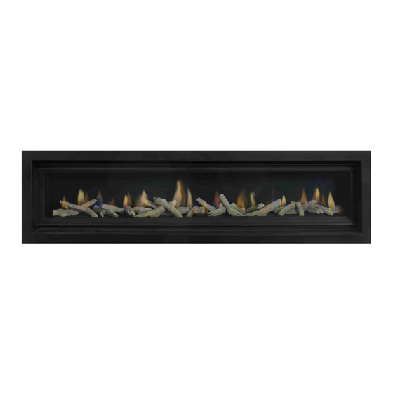
E L E M E N T 12 0 0 M A R K 2 & 18 0 0 M A R K 2
I N S T A L L A T I O N A N D O P E R A T I O N S M A N U A L
The Real Flame Element space heater is suitable to be installed into a frame out installation. Designed
to operate on Natural gas, LPG and ULPG
Approval no. GMK 10441
Consumer safety information: please read this manual before installing and operating this appliance.
Failure to follow these instructions may result in a possible fire hazard and/or injury and will void the
warranty.
Ve rsi on M2 .3
S P A C E H E A T E R S
A L L F L U E C O N F I G U R A T I O N S
Advertisement
Table of Contents

Related Manuals for Real Flame Element 1200 MARK 2


Summary of Contents for Real Flame Element 1200 MARK 2
- Page 1 I N S T A L L A T I O N A N D O P E R A T I O N S M A N U A L The Real Flame Element space heater is suitable to be installed into a frame out installation. Designed to operate on Natural gas, LPG and ULPG Approval no.
-
Page 2: Table Of Contents
C O N T E N T S WELC OME S PE CIFICAT IONS O P E R A T I O N I N S T R U C T I O N S USER INST R U C TIO NS WiFi D EV IC E C ON T R O L I N ST R U C T I O N S TR OUB LESHO OT I NG F O R YO U R F I R EP LACE I N S T A L L A T I O N I N S T R U C T I O N S... -
Page 3: Welc Ome
W E L C O M E Congratulations on your selection of the elegant Real Flame Element MK2 Fireplace. Enjoy mesmerising flame patterns in a truly efficient gas fireplace. The Element Range is simply breathtaking with its clean lines, beautiful flame pattern and multiple media options. We hope you create endless memories in front of this warm and cosy fireplace. -
Page 4: S Pe Cificat Ions
S P E C I F I C A T I O N S O F E L E M E N T 12 0 0 M K 2 Appliance Type High Efficiency Gas Fireplace Star Rating Up to 4.8 stars Maximum Heating Output Up to 8.7kW Heats Room up to... - Page 5 S P E C I F I C A T I O N S O F E L E M E N T 18 0 0 M K 2 Appliance Type High Efficiency Gas Fireplace Star Rating Up to 4.7 stars Maximum Heating Output Up to 9.1kW Heats Room up to...
- Page 6 O P E R A T I O N I N S T R U C T I O N S Page...
-
Page 7: User Inst R U C Tio Ns
U S E R I N S T R U C T I O N S • Do not operate if you smell gas. Turn appliance off, to light the fire. extinguish any open flame. Contact your installer or a licensed gasfitter. - Page 8 P ro gram mi ng • When the fire shuts off on auto mode or is shut off in Each day of the week can be programmed individually manual mode, the fan will continue to operate for up for 4 periods P1, P2, P3 and P4, making a total of 28 to 15 minutes.
- Page 9 similarly, using button. continually turn on and off. Press ‘OK’ to accept. • If leaving the house for an extended period, the RF Se t t in g t he t em p era t ure thermostat should be turned “OFF”. The temperature setting will now flash.
-
Page 10: Wifi D Ev Ic E C On T R O L I N St R U C T I O N S
St ep 2 W iF i S et -u p Download the Real Flame Fire MKII App from the App store or play store if you’re an Android user. From Factory settings the Fireplace will broadcast an Access Point for the Mobile App to join with, the Access... - Page 11 S te p 3 St ep 5 Open the App and click on Set up if you are a new user and have not Go to the WiFi setting on your phone and select your fireplace when established connection to your fireplace prior to this. the device prompts you to choose a network.
- Page 12 St ep 7 S tep 9 Once the fireplace is connected click on the information button and Congrats you have connected to the fireplace. Sit back, relax and select auto join for ease of connection in the future. increase or decrease the temperature as you please. S te p 8 S tep 10 Open the App and click on NO when this pops up.
- Page 13 S e t t i n g re m o t e a c c e ss S te p 11 f i re p l a c e Click OK when the option to rename appears and input the new (eg: Using the phone or tablet remotely to activate the fire when not name.
- Page 14 S te p 14 S tep 15 Subject to operating system the following should occur - Once the Clicking Yes will open the registration section which once completed connection is established, the system will transport you to the screen will allow you to access your fireplace from anywhere. Put in the below.
- Page 15 P u sh i n g t he Fi re p l a c e t o a di f f e re n t St ep 17 ho m e or l o c a l n e t wo rk a f t e r i n i ti a l Using device turn off fireplace.
- Page 16 AN DRO ID D EVICE I NST RUCT IO NS S te p 1 Ste p 3 Open Google play store on your device and search for the ‘Real Before you open the Fireplace app, open your WiFi setting and Flame Fire MKII”...
- Page 17 S te p 5 St ep 8 Once you click yes, this screen will appear. You have to now connect Congratulations your fire place is now connected! the fireplace to your WiFi network. Select your network and enter the Once you open the app once again, you’ll get a prompt to control password.
- Page 18 Ste p 12 S te p 10 To rename the fireplace and personalise it, go to settings and rename Congratulations! You can now access your fireplace remotely without as per your liking. the need to connect to your personal WiFi network. S te p 11 Now you can regulate the temperature of the fireplace as per your liking.
-
Page 19: Tr Oub Lesho Ot I Ng F O R Yo U R F I R Ep Lace
T R O U B L E S H O O T I N G F O R Y O U R F I R E P L A C E P rob le m Po ssi b l e C a u se Su g g e st e d So l u t i o n When the remote is activated nothing Gas supply is turned off or low... -
Page 20: I N S T A L L A T I O N I N S T R U C T I O N S
I N S T A L L A T I O N I N S T R U C T I O N S Page... -
Page 21: Unit D Im Ensi On S
U N I T D I M E N S I O N S UNIT E1200 452 74.5 74.5 1291 1 186 364 1400 E1800 1052 452 74.5 74.5 1891 1786 364 2000 UNIT E1200 E1800 Page... -
Page 22: Minimum Fr A Meou T Di Men S I On S
M I N I M U M F R A M E O U T D I M E N S I O N S 5 0MM TRIM UNIT E1200 1420 E1800 2020 460 combustible cladding to run beyond stud NOT E : and behind trim The appliance is to be installed prior to wall cladding and finishes. -
Page 23: Tr Im D Ime Ns Io Ns
12 0 0 T R I M D I M E N S I O N S 5 0MM T RIM 1 187 1291 18 MM TRI M FL A NG E K I T 1226 1376 18 MM LOW PROF IL E T R IM 10.0 1 187 1223... - Page 24 18 0 0 T R I M D I M E N S I O N S 5 0MM T RIM 1891 1787 18 MM TRI M FL A NG E K I T 1823 1787 18 MM LOW PROF IL E T R IM 1976 1826 Page...
-
Page 25: Installing El Ec Tr I C Eq U I Pmen T A B Ove Firep Lace
I N S T A L L I N G E L E C T R O N I C E Q U I P M E N T A B O V E Y O U R F I R E P L A C E Electronics can be installed in this Zone.* Keep clear of electronics... -
Page 26: 0 - 5 M F L U E C O N F I G U R A T I O N
0 - 5 M F L U E C O N F I G U R A T I O N Page... -
Page 27: Installat Io N In St R U C T I On S
I N S T A L L A T I O N I N S T R U C T I O N S LO C AT IO N Do not exceed maximum rated pressures. Select a location where the fire can be supervised during operation. - Page 28 F lu e r u n s 0m t o 5m l e ng th ( exclu di ng 0 - 5 m ro of t op t er mi na ti o n) External wall mount outlet with integrated flue fan (0-5m Flue run model) External wall mount terminal (Flue fan installed above appliance internally) (0-5m Flue run model) Page...
- Page 29 F lu e r u n s 0m t o 5m l e ng th ro of to p ter mi na ti o n on ly Vertical roof termination (S/Steel rooftop termination) affected. FL U E T ERMI NATIO N LO CAT IONS This section is used to determine where your Balanced •...
- Page 30 F lu e r u n s 0m t o 5m l e ng th ro of to p ter mi na ti o n w i th e x t e rna l mo t or Page...
-
Page 31: Ex T Er Nal Wa L L Mo U N Ted Fa N M Odule In Stall Atio N
E X T E R N A L W A L L M O U N T E D F A N M O D U L E I N S T A L L A T I O N Apply an 8mm silicon bead fully around the inside of the flue end... - Page 32 Feed air intake flue pipe through location spigot and fit retaining screw. Remove wall mount plate Push connection plate into from flue connection plate. approximate position. Cut flue exhaust tube (hot tube) length (Approximately flush with wall exit). Connection plate will sit against wall. Locate wall mounting...
- Page 33 Assemble main body assembly onto wall mounting bracket, feed power cable through grommet hole prior to fitting. (refit 5 screws as shown and tighten) Main body assembly must sit flush up against the mounting bracket and seal. Connect power cable connector.
-
Page 34: Int E Rna L Fan A N D Wa L L Ter M I N Ati On In Sta Llat Io N
0 M - 5 M F L U E I N T E R N A L F A N A N D W A L L T E R M I N A T I O N I N S T A L L A T I O N Page... - Page 35 Se t u p wi t h in t er na l f an modul e with w a l l t e r mi n at i on – appl ian ce mo un ted Apply an 8mm thick Maximum 5m flue length silicon bead fully around the lower fan connection...
- Page 36 Slide flue onto connection Locate 2nd clamp onto lower connection and tighten spigot fully. clamp fully. Tighten clamp fully. Wipe excess silicon, visually check connection to ensure connection is fully sealed. Wipe excess silicon, visually check connection to ensure connection is fully sealed.
- Page 37 7. Connection to wall terminal Apply an 8mm silicon Loose fit connections (wall termination connections) bead fully around the inside of the flue end (heater connection end) Fit flue clamp over flue (loosely). Slide flue onto connection spigot fully. Tighten clamp fully. Wipe excess silicon,...
- Page 38 Feed hot exhaust flue into connection, ensure inserted 50mm. Fit retaining screw from below. Feed intake flue into connection, ensure inserted 50mm. Fit retaining screw from below. Push terminal into approximate position and affix onto wall. Page...
- Page 39 S e t u p w it h i nt ern al fa n mod ule with w al l Cut tube to length where te r m i n at i on – m i d f l u e mou nted required.
- Page 40 Slide flue onto connection spigot fully. Tighten clamp fully. Wipe excess silicon, visually check connection to ensure connection is fully sealed. Repeat for connection to underside of fan module. 6. Connect power lead to fan module. Ensure lead is clipped support where required.
- Page 41 Locate terminal on wall and predrill mounting holes where required. Cut flue exhaust tube (hot tube) to length (Flue must extend a minimum of 50mm past the exit face of wall.) It is recommended that the tubes are cut slightly longer and pushed back into wall upon fixing of wall terminal.
-
Page 42: Int E Rna L Fan A N D R O O F Ter M I N At I On
I N T E R N A L F A N & R O O F T E R M I N A T I O N Page... - Page 43 Se t u p w it h i nt ernal f an module w ith ro of to p Run flue from appliance t e r mi n at i on – mi d f lu e mo unte d to bottom entry on fan Maximum 5m flue length module.
- Page 44 Slide flue onto connection spigot fully. Tighten clamp fully. Wipe excess silicon, visually check connection to ensure connection is fully sealed. Repeat for connection to underside of fan module. 5. Connect power lead to fan module. Repeat for air intake flue Ensure lead is clipped connection.
- Page 45 Cut rooftop penetration to length if required. IMP O RTAN T- Apply silicon bead between Install in to roof penetration. inner connection of cowl and flue pipe to seal Install supports for base of penetration kit. inner flue to cowl. Outer does not require sealing.
-
Page 46: Rooftop T Er Mi N Ati O N W I Th Ext Er N A L Moto R
R O O F T O P T E R M I N A T I O N W I T H E X T E R N A L M O T O R Page... - Page 47 Se t u p w it h ext ernal ro of top ter min a tion Slide flue onto connection Maximum 5m flue length spigot fully. Tighten clamp fully. Wipe excess silicon, visually check connection to ensure connection is Ro o f to p t erm i nat i on fully sealed.
- Page 48 Connect the fan power cable from the appliance Fit the termination on to the to the termination. access panel and match the rivet holes to rivet the Ensure cable termination to the access clamped only to the intake panel. pipe to secure the cable from hanging loose &...
-
Page 49: 5 - 10 M I N S U L A T E D F L U E C O N F I G U R A T I O N
5 - 10 M I N S U L A T E D F L U E C O N F I G U R A T I O N Page... -
Page 50: Installat Io N In St R U C T I On
I N S T A L L A T I O N I N S T R U C T I O N S LO C AT IO N Do not exceed maximum rated pressures. Select a location where the fire can be supervised during operation. - Page 51 F lu e r u n s 5m t o 10m le ng th ( exclu di ng 5 - 10 m roo f t op t er mi na ti o n) External wall mount outlet with integrated flue fan (5-10m Flue run model) External wall mount terminal (Flue fan installed above appliance internally) (5-10m Flue run model) Page...
- Page 52 F lu e r u n s 5m t o 10m le ng th ro of to p termi nati o n o nl y Vertical roof termination (S/Steel rooftop termination) affected. F L UE T ERMI N ATIO N LO CAT IONS This section is used to determine where your Balanced •...
- Page 53 F lu e r u n s 5m t o 10m le ng th ro of to p termi nati o n w it h ex te rn al m ot o r AIR INTAKE 75MM ALUMINUM FLUE MAXIUMUM RUN 10M WITH 6 BENDS SUPPLIED AS 10M LENGTH EXHUST FLUE 75MM ALUMINUM FLUE MAY BE CUT TO LENGTH...
-
Page 54: Ex T Er Nal Wa L L Mo U N Ted Fa N M Odule In Stall Atio N
E X T E R N A L W A L L M O U N T E D F A N M O D U L E I N S T A L L A T I O N Recommended Silicon –... - Page 55 5. Repeat above with air intake flue pipe to heater Cut flue exhaust tube connection. (hot tube) length (Approximately flush with 6. Clip flues as required to provide adequate support. wall exit). Connection 6. Connection to wall mounted fan terminal. plate will sit against wall.
- Page 56 Fit flue exhaust insulation Locate wall mounting bracket into position and Insulated with 25mm foil affix to wall. faces glasswool pipe insulation within 0.3m of each end of flue, as supplied by Glen Dimplex Australia. Insulation must start as close to the gas space heater as possible Assemble spigot (Only exhaust flue is to be insulated)
- Page 57 Insulation must be fitted prior and after the inline powerflue fan. Failure to fit insulation on the exhaust flue may result in condensation failures with the appliance. Connect power cable connector. Fit cable clamp to cable. Fit front cover. Page...
-
Page 58: Int E Rna L Fan A N D Wa L L Ter M I N Ati On In Sta Llat Io N
5 M - 10 M F L U E I N T E R N A L F A N A N D W A L L T E R M I N A T I O N I N S T A L L A T I O N 10MFAFX2 10MFAFX2 Exhaust flue must be insulated using 25mm... - Page 59 Se t u p wi t h in t er na l f an modul e with w a l l Check 75mm flue piece t e r mi n at i on – appl ian ce mo un ted for correct shape and Maximum 10m flue length fitment onto appliance...
- Page 60 Turn fan assembly upside Fit hot exhaust flue pipe down and slide 65mm flue from outlet termination to section fully onto spigot. fan outlet connection. Fit flue clamp and tighten Cut tube to length where clamp fully. required. Wipe excess silicon, Ensure ends are burr free visually check connection...
- Page 61 Fit air intake flue pipe to heater connection. Cut tube to length where Clip flues as required to required. provide adequate support. Ensure ends are burr free and round, test fit flue will slide over connection. 7. Connection to wall terminal Loose fit connections (wall termination connections) Apply an 8mm thick silicon bead fully around...
- Page 62 Push terminal into approximate position and affix onto wall. Locate terminal on wall and predrill mounting holes where required. Cut flue exhaust tube (hot tube) to length (Flue must extend a minimum of 50mm past the exit face of wall.) It is recommended that the tubes are cut slightly longer and pushed back into wall upon fixing of wall terminal.
- Page 63 Bends were practical should be insulated, by cutting the insulation into segments taping together. Joins taped together using aluminum foil self adhesive tape. Insulation must be fitted prior and after the inline powerflue fan. Failure to fit insulation on the exhaust flue may result in condensation failures with the appliance.
- Page 64 S e t u p w it h i nt ern al fa n mod ule with w al l 5. Insulation Instructions- te r m i n at i on – m i d f l u e mou nted Maximum 10m flue length Exhaust flue must be insulated using 25mm glass wool pipe insulation as supplied by Glen Dimplex Australia.
- Page 65 Apply an 8mm thick silicon Slide flue onto connection bead fully around heater spigot fully. connection approx. 10mm from the top. Tighten clamp fully. Apply an 8mm silicon Wipe excess silicon, bead fully around the visually check connection inside of the flue end to ensure connection is (heater connection end) fully sealed...
- Page 66 Connection to wall terminal Feed hot exhaust flue Loose fit connections (wall termination connections) into connection, ensure inserted 50mm. Fit retaining screw from below. Feed intake flue into connection, ensure inserted 50mm. Fit retaining screw from below. Fit flue exhaust insulation Insulated with 25mm foil faces glasswool...
- Page 67 Bends were practical should be insulated, by cutting the insulation into segments taping together. Joins taped together using aluminum foil self adhesive tape. Insulation must be fitted prior and after the inline powerflue fan. Failure to fit insulation on the exhaust flue may result in condensation failures with the appliance.
-
Page 68: Int E Rna L Fan A N D R O O F Ter M I N At I On
I N T E R N A L F A N & R O O F T E R M I N A T I O N 10MFAFX2 10MFAFX2 Exhaust flue must be insulated using 25mm glass wool pipe insulation as supplied by Glen Dimplex Australia. - Page 69 Se t u p w it h i nt ernal f an module w ith ro of to p Run flue from appliance t e r mi n at i on – mi d f lu e mo unte d to bottom entry on fan Maximum 10m flue length module.
- Page 70 Slide flue onto connection spigot fully. Tighten clamp fully. Wipe excess silicon, visually check connection to ensure connection is fully sealed. Repeat for connection to underside of fan module. 5. Connect power Repeat for air intake flue lead to fan module. connection.
- Page 71 IM P O RTA NT- Apply Cut rooftop penetration to length if required. silicon bead between Install in to roof penetration. inner connection of cowl and flue pipe to seal Install supports for base of penetration kit. inner flue to cowl. Outer does not require sealing.
- Page 72 Bends were practical should be insulated, by cutting the insulation into segments taping together. Joins taped together using aluminum foil self adhesive tape. Insulation must be fitted prior and after the inline powerflue fan. Failure to fit insulation on the exhaust flue may result in condensation failures with the appliance.
-
Page 73: Rooftop T Er Mi N Ati O N W I Th Ext Er N A L Moto R
R O O F T O P T E R M I N A T I O N W I T H E X T E R N A L M O T O R 5 T O 10 m F L U E R U N AIR INTAKE 75MM ALUMINUM FLUE MAXIUMUM RUN 10M WITH 6 BENDS SUPPLIED AS 10M LENGTH... - Page 74 Se t u p w it h ext ernal ro of top ter min a tion On the heater connection Maximum 10m flue length end - Fit clamp loosely & apply silicon inside the pipes. Apply an 8mm silicon bead fully around the inside of the flue and Ro o f to p t erm i nat i on on the heater spigot.
- Page 75 Fit the access panel to the roof penetration. Use the screw holes fix the access panel to the roof penetration. On the termination end - Fit clamp loosely & apply silicon inside the pipes. Apply an 8mm silicon bead fully around the inside of the flue and on the flue spigot.
- Page 76 Connect the fan power cable from the appliance to the termination. Joins taped together using aluminum Ensure cable foil self adhesive tape. clamped only to the intake pipe to secure the cable from hanging loose & touching the hot flue gases pipe.
-
Page 77: P O L Y P R O P Y L E N E F L U E C O N F I G U R A T I O N
10 - 13 . 5 M P O L Y P R O P Y L E N E F L U E C O N F I G U R A T I O N Page... -
Page 78: Installat Io N In St R U C T I On S
I N S T A L L A T I O N I N S T R U C T I O N S LO C AT IO N Do not exceed maximum rated pressures. Select a location where the fire can be supervised during operation. - Page 79 F L U E TE RMI NATIO N LO CATION P O L Y P R O G E N E R A L I N S T A L L A T I O N This section is used to determine where your flue R E Q U I R E M E N T S termination will be located.
- Page 80 Duravent and other certain clamp styles, 1/4˝ or greater All-thread may be used as an extension. 6. Vertical installations must be supported every 3 meters or less. 7. Elbows and tees are sufficiently supported when a bracket is fixed at the female end of the connected straight section.
- Page 81 Page...
-
Page 82: S Et Up Wit H Exte R N A L Wa L L Mou N T Ed Fa N T Ermin A L
S E T U P W I T H E X T E R N A L W A L L M O U N T E D F A N T E R M I N A L Maximum 13.5m flue length Instructions are in 3 sections 1. - Page 83 I MP OR TAN T IN STAL L AT IO N NOT E S · Flexi flue must be fully extended to length. 5m for exhaust flue and 2 x 7m for inlet. · 5m of flexi flue on the exhaust side MUST be used before prior to converting to polypropylene. Failure to do this will result in appliance shutdown.
- Page 84 IN TA K E P I P E CON N ECTIO N TO APPLIAN CE In t a ke pi p e j oi ne r c o n ne ct i o n Flexi flue is provided for air intake.
- Page 85 Assemble spigot connection plate assembly to wall mounting bracket. (4 screws) Slide each flue halfway onto connection joiner. Tighten clamp fully. Wipe excess silicon, visually check connection to ensure connection is fully sealed. O UTL E T CON N E C TI O N F RO M H E ATE R Note: The full 5m of flexi In ta ke conn ec t ion to wall m ounte d fan termi nal flue must be used.
- Page 86 1 / 1 joiner connection. n contained herein is the sole property of real flame pty ltd. Deburr and break All Sharp Corners al, it is to be returned upon request and is not to be copied or comunicated to any other ent of real flame pty ltd.
- Page 87 Po ly Pro t o Pol y Pro f lue co n nec tion Verify gasket is sitting correctly. Apply a light soapy water film to the gasket and tube end. Insert pipe fully into end fitting, Pipe will push in smoothly and evenly, should this not occur remove pipe and reset gasket.
- Page 88 Remove cover from fan terminal Assemble spigot Remove main assembly connection plate assembly from rear wall to wall mounting bracket. mounting plate assembly. (4 screws) Remove the 5 screws as shown. (Do not remove fan plate screws) Lift off main fan terminal assembly.
- Page 89 Connect power cable connector. Fit cable clamp to cable. Fit front cover. Page...
-
Page 90: Int E Rna L Fan A N D Wa L L Ter M I N Ati On In Sta Llat Io N
S E T U P W I T H A P P L I A N C E M O U N T E D F A N O R I N L I N E M O U N T E D F A N A N D W A L L T E R M I N A L Maximum 13.5m flue length Instructions are in 3 sections... - Page 91 Apply an 8mm thick silicon bead fully around heater connection approx. 10mm from the top. I MP OR TAN T IN STAL L AT IO N NOT E S Flexi flue is in 7m lengths. A maximum of 2 lengths can Flexi flue must be fully extended to length.
- Page 92 Ai r i nt ake p ip e - In take co nn e ct io n t o w al l mo un te d fa n t e rm in al Ensure ends are burr free and round, test fit flue will slide over connection joiner.
- Page 93 Fit 2nd flue clamp loosely Recommended Silicon – Non-acetic, neutral cure onto the 65mm section of 150degc or higher temperature rated. flue. Bostik RTV 926 or similar. Lift fan assembly into Apply an 8mm thick silicon bead fully around heater appliance and locate onto connection approx.
- Page 94 Revision 1 / 1 on contained herein is the sole property of real flame pty ltd. Deburr and break All Sharp Corners al, it is to be returned upon request and is not to be copied or comunicated to any other sent of real flame pty ltd.
- Page 95 Fit flue clamp over flue (loosely). Slide flue onto connection spigot fully. Tighten clamp fully. Wipe excess silicon, visually check connection to ensure connection is fully sealed. Apply soapy water to ring in Poly Pro flue and dampen surface of connector.
- Page 96 Po l y P ro t o Poly P ro fl ue con n ectio n Verify gasket is sitting correctly. Apply a light soapy water film to the gasket and tube end. Insert pipe fully into end fitting, Pipe will push in smoothly and evenly, should this not occur remove pipe and reset gasket.
- Page 97 Assemble condensate drain and attach to pipe exiting wall. PVC pressure pipe cement must be used. 40mm PVC pipe must be fitted (not shown) to drain to waste Components supplied loose. 15mm PVC Elbow or 15mm STRAIGHT CONNECTOR 15mm PVC class 18 tube 15mm PVC to 15mm threaded union 15mm to 20mm union 20mm to 40mm union...
- Page 98 10 - 13 . 5 M R O O F T O P P O L Y P R O P Y L E N E F L U E C O N F I G U R A T I O N Page...
-
Page 99: Installat Io N In St R U C T I On
I N S T A L L A T I O N I N S T R U C T I O N S LO C AT IO N Do not exceed maximum rated pressures. Select a location where the fire can be supervised during operation. - Page 100 F L U E TE RMI NATIO N LO CATION P O L Y P R O G E N E R A L I N S T A L L A T I O N This section is used to determine where your flue R E Q U I R E M E N T S termination will be located.
- Page 101 Duravent and other certain clamp styles, 1/4˝ or greater All-thread may be used as an extension. 6. Vertical installations must be supported every 3 meters or less. 7. Elbows and tees are sufficiently supported when a bracket is fixed at the female end of the connected straight section.
- Page 102 Page...
-
Page 103: S Et Up Wit H Inl I N E Or A P Pl I A Nc E Mo U N T Ed Fa N
S E T U P W I T H I N L I N E O R A P P L I A N C E M O U N T E D F A N Page... - Page 104 IN TA K E P I P E CON N ECTIO N TO APPLIAN CE In t a ke pi p e j oi ne r c o n ne ct i o n Flexi flue is provided for air intake.
- Page 105 Apply an 8mm thick silicon bead fully around heater connection approx. 10mm from the top. Slide each flue halfway onto connection joiner. Tighten clamp fully. Wipe excess silicon, visually check connection to ensure connection is fully sealed. Apply an 8mm silicon bead fully around the inside of the flue end (heater connection end)
- Page 106 D.F. Treatment Drawing No Revision 1 / 1 n contained herein is the sole property of real flame pty ltd. Scoresby Victoria 3179 Material Finish Deburr and break All Sharp Corners al, it is to be returned upon request and is not to be copied or comunicated to any other by Victoria 3179 1.0MM M/STEEL...
- Page 107 Co n d ens at e d rai n - P trap f it ti ng NOTE – DRAINAGE MUST FALL TOWARDS CONDENSATE TRAP LOCATED AT THE END OF THE ALUMINUM FLUE SECTION A P-TRAP MUST BE INSTALLED AS SHOWN Ins t all at i on Connect 90deg elbow to Aluminum adapter facing downwards...
- Page 108 Po l y P ro t o Roof t e rmi na tio n Ensure termination is supported. Join Poly flue to rooftop termination Ensure clip is fixed to prevent flue pipes from separating. Support flues. W IR IN G – F LUE T E MP ER ATURE L IM IT ING D EV I C E The flue temperature limiting device is inbuilt into the extension wiring and the flue adapter.
-
Page 109: Commissio Nin G P R O C Edu R E
C O M M I S S I O N I N G P R O C E D U R E O n c e t he f ire is i nst a ll ed : 1. Install media. 2. -
Page 110: Me Dia Instal L Ati O N
M E D I A I N S T A L L A T I O N P L E AS E NOTE: not all media options shown are available for sale. Refer to Glen Dimplex Australia for available options. G E N ER AL I NSTAL L ATIO N NOT E Lay media in a random arrangement along the entire length of the burner. - Page 111 D ri f t wo od Ar ra ngement I nstr uct ion Media must be laid out from corner to corner of the • Start media placement from a corner with logs over firebox. Start media placement from a corner by placing side plate.
- Page 112 Lo g s a nd Co al Ar ra ngement I nstr uct ion C R I T I C A L A R R A N G E M E N T S T O A V O I D •...
- Page 113 Redgum w ith ass o r te d co als Ar ra ngement I nstr uct ion Media must be laid out from corner to corner of the Spread coals randomly on and along the burner, avoid firebox. Start media placement from a corner by placing blocking the burner channel.
- Page 114 Coa ls only Pe bb le s • Lay coal media in a random arrangement along the • Lay large pebble media in a random arrangement entire length of the burner. along the entire length of the burner. • Avoid smothering the burner channel. Apply coals •...
-
Page 115: Conv Er Sion D Eta I L S
C O N V E R S I O N D E T A I L S / I N J E C T O R – P I L O T A N D B U R N E R R E M O V A L N at u ra l ga s / P rop a ne /UL PG Remove air deflector and air intake grate... - Page 116 Remove side panels and liners to access burner locating Lift burner and gently support. wingnuts. Undo gas connection pipe at end of burner. (15mm and 16mm spanner required) Remove burner fixing screws (2 off at ends of burner) Detach the burner Undo wingnuts to remove burner and lift burner from position.
- Page 117 The media may be carefully lifted out and placed flat to store until refitting. The media can be repainted using an approved high temperature paint, contact Real Flame for details. Turn burner over gently. AVOIDING DAMAGING THE INSULATION Loosen gas pipe nuts form injectors and move gas pipe away.
- Page 118 TAKE CARE – where the burner has been previously used the hard insulation is easily cracked. The insulation media can be repainted using an approved high temperature paint, contact Real Flame for details. Page 1 18...
- Page 119 Remove spark lead Remove spark probe (10mm spanner required) PILOT Remove pilot pipe fitting from pilot assembly. Re m ove pi lot c ove r scre en. Remove pilot orifice from pilot or replace whole pilot Gently lift pilot assembly up to enable access to pipe assembly with correct gas type.
- Page 120 PILOT RE-FITMENT BURNER RE-FITMENT Replace pilot orifice with correct gas type. Carefully place burner into firebox, supporting LH end of Refit pilot gas pipe and tighten the burner. Refit spark probe and gently tightly Tighten gas pipe connection to the end of the burner. Refit spark lead Burner can now be lowered fully into the firebox.
- Page 121 Check appliance for correct flame operation, Check pilot flame, Check main burner is not smothered and flames are even along burner with correct colour and not excessively yellow or sooty. (Note it takes upto 10minutes of operation for the flame to achieve full colour.) Remove manometer and tighten test point.
-
Page 122: Pa Rts L Ist
P A R T S L I S T Pa r ts P i c t u re Valve SIT Pilot assembly- refer gas type Injector Natural gas- refer gas type Millenium receiver Millennium remote control Techrite Ignition System Page... -
Page 123: Ap Pe Ndix 1- Fl U E Ter Mi N Ati O N
A P P E N D I X 1 - F L U E T E R M I N A T I O N Page... -
Page 124: Ap Pe Ndix 2- W I R I N G Di Ag R A Ms
A P P E N D I X 2 - W I R I N G D I A G R A M S Techr ite Ig nit ion Pa ck GLEN DIMPLEX AUSTRALIA PTY LTD - ELEMENT 1200-1800 WIRING CP-R160-D5 IGNITION WARNING - ISOLATE POWER BEFORE SERVICING Page... -
Page 125: Wa Rra Nt Y I Nfo R Mati O N
W A R R A N T Y I N F O R M A T I O N The benefits provided to you under the following warranty are in Supplier Name___________________________________ addition to any other rights and remedies available to you under the law. - Page 126 Website: Telephone: www.realflame.com.au AU: 1300 554 155 www.realflame.co.nz NZ: +64 9 274 8265 Glen Dimplex. All rights reserved. Material contained in this publication may not be reproduced in whole or in part, without prior permission in writing from Glen Dimplex.
Need help?
Do you have a question about the Element 1200 MARK 2 and is the answer not in the manual?
Questions and answers