Real Flame 700 Installation & Operating Manual
Inspire flame effect space heater
Hide thumbs
Also See for 700:
- Installation & operating manual (40 pages) ,
- Installation & operating manual (8 pages)
Table of Contents

Related Manuals for Real Flame 700


Summary of Contents for Real Flame 700
- Page 1 INSPIRE FLAME EFFECT SPACE HEATER MODELS 700/900/1100 INSTALLATION & OPERATING MANUAL The Inspire space heater is suitable to be installed into a frame out installation. Designed to operate on Natural gas and LPG gas. Approval no.GMK 10528 Version 10A...
- Page 2 Model / Serial Number _______________________ This warranty does not cover the cost of claiming under the warranty or transporting the Real Flame Gas Burner to and from the supplier Our goods come with guarantees that cannot be excluded under the Australian Consumer Law. You are entitled to a replacement or refund for a major failure and for compensation for any other reasonably foreseeable loss or damage.
- Page 3 WARNING The Inspire space heater has a primary safety glass fitted in front of the glass door. This safety glass is fitted to this appliance to reduce the risk of injury from burns and at no time should this glass be permanently removed. For protection of young children or the infirm, a secondary guard is required.
-
Page 4: Table Of Contents
TROUBLESHOOTING ............................42 WIRING DIAGRAM ............................. 44 AERATION ADJUSTMENTS and BURNER SIZES ....................45 CONVERSION DETAILS - Natural gas /LPG ......................46 INSPIRE 700 MODEL ............................46 INSPIRE 900 MODEL ............................47 INSPIRE 1100 MODEL ............................ 48 PARTS LIST ................................. 49... -
Page 5: Data Plate
DATA PLATE (Affixed to the base of the unit for reference to gas pressure & consumption) Inspire 700 GAS TYPE INJECTOR SIZE N.G.C. (MJ/hr) 0.88kPa High Natural Gas 1 X 2.30mm 22.0 High/16.0 Low 0.40kPaLow 2.48kPa High 1 X 1.35mm 22.0 High/17.0 Low... -
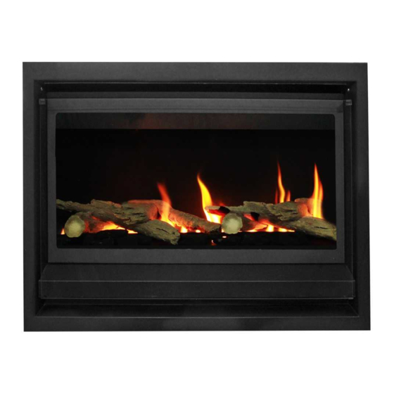
Page 6: Inspire 700
Inspire 700 Inspire 900 P a g e... -
Page 7: Inspire 1100
Inspire 1100 Power Flue P a g e... -
Page 8: Location
LOCATION Select a location where the fire can be supervised during operation. An electrical isolation switch must be fitted at the appliance or on an adjacent wall to allow for emergency shutdown and maintenance. Installation must meet Australian gas codes AS/NZS 5601. INSTALLATION CLEARANCES –... -
Page 9: Flue Termination Location
Flue must be clipped and supported support. Connections must be sealed with silicon and clamped where advised. Recommended Silicon – Non acetic, neutral cure 200degrees or higher temperature rated. Bostik RTV 926 or similar. U style flue runs must not be installed FLUE TERMINATION LOCATION •... - Page 10 INSPIRE FLUE TERMINAL LOCATION P a g e...
-
Page 11: Setup With External Wall Mounted Fan Terminal
SETUP WITH EXTERNAL WALL MOUNTED FAN TERMINAL Wall mounted fan module – terminal must be installed with clearances as specified by AS/NZS 5601.1 Clause 6.9.3 Run exhaust flue and air intake flue as required Maximum run 5mts. Flues can be run next to each other. - Page 12 Recommended Silicon – Non-acetic, neutral cure 150degc or higher temperature rated. Bostik RTV 926 or similar. Apply an 8mm thick silicon bead fully around heater connection approx. 10mm from the top. Apply an 8mm thick silicon bead fully around the lower fan connection spigot approx.
- Page 13 Cut flue exhaust tube (hot tube) to length (approximately flush with wall exit). Wall termination will sit against wall. Pull flue tube through approx. 100mm further (will be pushed back once terminal fitted). Feed power cable through wall and into wall terminal.
- Page 14 Push fan terminal into position. And affix to wall. Uneven or rough surfaces may require sealant along top and side gaps. Connect power cable connector. Fit cable clamp to cable. Fit front cover 13 | P a g e...
-
Page 15: Rooftop Powerflue Termination
ROOFTOP POWERFLUE TERMINATION Insulation requirements for flue runs NOTE: Insulation is used for rooftop termination installations only The insulation supplied is in lengths of 1000mm The termination must be installed at a minimum height of 350mm from the lowest point of the termination to closest point on the roof (Refer image above) ... - Page 16 Example: For a flue run of 8.5mts Flue run length N = 8.5mts Minimum insulation required X = N - 1 mts = 8.5 - 1 = 7.5 mts Insulation is supplied in lengths of 1000mm. Initial 300mm from appliance exit may remain uninsulated (Refer image below) Last 700mm from rooftop termination down may remain uninsulated.
- Page 17 Instructions: Rooftop fan module – Terminal must be installed with clearances as specified by AS/NZS 5601.1 Clause 6.9.3 Run exhaust flue and air intake flue as required Maximum run 8.5mts. Flues can be run next to each other. Maintain the required clearances to combustibles.
- Page 18 42mm 42mm 112mm Insulation cut pattern for 90° bend 112mm 112mm 42mm For 90° and 45° bends the corners must be insulated. For a 90˚ bend with a minimum bend radius is 150mm. Cut the insulation diagonally into 3 pieces in a cone shape.
- Page 19 Insert the roof penetration and fix firmly to the roof structure using appropriate supports. The roof penetration flue is a 250mm rigid flue. Fit the access panel to the roof penetration Use the screw holes fix the access panel to the roof penetration.
- Page 20 Slide flue onto connection spigot fully. Tighten clamp fully. Wipe excess silicon, visually check connection to ensure connection is fully sealed. Ensure that the pipes are connected correctly and are not inverted. Use the labels to identify exhaust and intake spigots Connect the fan power cable from the appliance to the termination.
-
Page 21: Timber Frame Installation
TIMBER FRAME INSTALLATION Frame out Dimensions (in mm) 1500 1110 * Indication only. Can be smaller or larger. Notes: 1. At frame stage the builder shall provide a 10amp GPO to the rear back corner of the frame out with an isolation switch fitted at the appliance or on an adjacent wall within the room where the fire can be seen. - Page 22 TIMBER FRAME INSTALLATION - PRE HANDOVER OPTION (continued) Notes (continued): 2. Pre plastering, the installer shall install the termination (vertical or horizontal) run the twin 75mm ID flues from the termination to inside the frame out (label them exhaust and intake) and terminate 500mm from the base.
-
Page 23: Media Installation
1. Driftwood 2. Pebbles Refer to correct section for media set up. Driftwood Media – Inspire 700 Model a) Place branch log 1 supports as shown. b) Place No 2. Long log across branch log, using location grooves to locate. - Page 24 c) Place No 3 log short crossover log over the long log, use location groove to locate. d) Place log No 4 over log 3, use groove to locate. e) Place the second branch log 1 onto support. 23 | P a g e...
- Page 25 f) Place 2nd log No. 2 log onto branch log, use location grooves to locate. g) Place 2 log No 3 onto long log, use location groove to locate. Place mixed coals around logs along front section, DO NOT PLACE ON BURNER. 24 | P a g e...
- Page 26 Pebbles Media - INSPIRE 700 Model Locate side trays on either side of the firebox. Ensure that they are sitting flush against the side walls and screw them in from the front (if the trays do not sit flat then use the rear screw holes to screw them down).
- Page 27 Driftwood media - Inspire 900 Model a) 900 MODEL - Place Log 5 as shown in the image below. Near LH end. b) Place log 6 across log 5 using location grooves to locate. c) Place log 1 as shown in the image below. 26 | P a g e...
- Page 28 d) Place log 2 across log 1, using location grooves to locate. e) Place log 3 (short crossover) across log 2, using location groove to locate. f) Place log 4 over log 3, using groove to locate. 27 | P a g e...
- Page 29 g) Place Log 1 as shown in the image below. h) Place Log 2 across Log 1, using location grooves to locate. i) Place Log 3 (short crossover) over log 2, using location groove to locate. 28 | P a g e...
- Page 30 j) Place Log 4 over log 3, use groove to locate. Place mixed coals around logs along front section, DO NOT PLACE ON BURNER. 29 | P a g e...
- Page 31 Driftwood media - Inspire 1100 model a) Place Log 5 as shown in the image below b) Place log 6 across log 5 using location grooves to locate. c) Place log 1 as shown in the image below. 30 | P a g e...
- Page 32 d) Place log 2 across log 1, using location grooves to locate. e) Place log 3 (short crossover) across log 2, using location groove to locate. f) Place log 4 over log 3, using groove to locate. 31 | P a g e...
- Page 33 g) Place Log 1 as shown in the image below. h) Place Log 2 across Log 1, using location grooves to locate. i) Place Log 3 (short crossover) over log 2, using location groove to locate. 32 | P a g e...
- Page 34 j) Place Log 4 over log 3, use groove to locate. k) Place Log 8 as shown in the image below. l) Place log 9 across log 8 as shown 33 | P a g e...
- Page 35 m) Place Log 3 over log 9, use locating groove to locate. n) Place assorted coals (random placing) on the front plate as shown in the image below. 34 | P a g e...
- Page 36 Pebble media a) Ensure the rear media support is firmly located in position b) Place pebbles in random colors / size along back support. c) Place front pebbles in random colors / size along front - DO NOT PLACE ANY MEDIA ON BURNER 35 | P a g e...
-
Page 37: Commissioning Procedure
COMMISSIONING PROCEDURE Once the fire is installed. • Install media. • Connect to gas and power. • Fit firebox door. • Check for gas leaks. • Connect powerflue module loom to fan control unit. • Carry out the lighting procedure. •... -
Page 38: Remote Control Operation
REMOTE CONTROL OPERATION Note • Not all remote control functions are available. • In the event of loss of power, the appliance will shut down safely. The appliance may automatically resume operation once power is restored, pending the operation mode of the remote control. Transmitter LCD display TECHNICAL DATA Remote Control... - Page 39 Temperature indication display With the system in the OFF position, press the thermostat key and the mode key at the same time. Look at the LCD screen on the transmitter to verify that a C or F is visible to the right of the room temperature display.
- Page 40 Room thermostat (Transmitter Operation) The remote control can operate as a room thermostat. The thermostat can be set to a desired temperature to control the comfort level in a room. To activate this function, press the thermostat key. The LCD display on the transmitter will change to show that the room thermostat is “ON”...
- Page 41 Continuous pilot/intermittent pilot (CPI/IPI) selection With the system in “OFF” position, press the mode key to index to the CPI mode icon. Pressing the Up arrow key will activate the Continuous Pilot Ignition mode (CPI). Pressing the Down arrow key will return to IPI. A single “beep” will confirm reception of the command. NOTE: This fire is designed to run in IPI mode (Intermittent Pilot).
- Page 42 Remote auxiliary relay control - this function is not supported on this fire. Changes to the remote settings will not affect or change the appliance operation. 41 | P a g e...
-
Page 43: Troubleshooting
• Turn off appliance and the have door seal inspected by service personnel or Real Flame agent. Room air fan is noisy Faulty or dirty fan • Fan to be inspected and cleaned or not working •... - Page 44 TEACHING RF CODE – Reprogramming remote to heater 1. Electrical tray must be slid forward to reprogram a remote control. 2. Turn the remote to off mode 3. Turn mains power to heater on. 4. Press the red button on the receiver once – three beeps should be heard. 5.
-
Page 45: Wiring Diagram
WIRING DIAGRAM 44 | P a g e... -
Page 46: Aeration Adjustments And Burner Sizes
26.0 Inspire 1100 Pebbles 16.0 2. Fan restrictor (mounted in outlet tube of power flue fan) – 31.8mm diameter 3. Burner sizes - models for appliance Inspire 700 Nat Gas BEKEART Furigas- 0346 440mm long 50mm diameter Inspire 700 LPG... -
Page 47: Conversion Details - Natural Gas /Lpg
CONVERSION DETAILS - Natural gas /LPG INSPIRE 700 MODEL Valve, pilot injector, main burner injector and burner aeration cap must be changed to suit gas type. VALVE CHANGE 1. Turn appliance off. 2. Turn gas supply off. 3. Remove trim. -
Page 48: Inspire 900 Model
INSPIRE 900 MODEL Valve, pilot injector, burner, main burner injector and burner aeration cap must be changed to suit gas type. VALVE CHANGE 1. Turn appliance off. 2. Turn gas supply off. 3. Remove trim. 4. Disconnect gas pipe from isolation valve to burner. 5. -
Page 49: Inspire 1100 Model
INSPIRE 1100 MODEL Valve, pilot injector, burner, main burner injector, burner aeration cap and rear burner shield must be changed to suit gas type. VALVE CHANGE 1. Turn appliance off. 2. Turn gas supply off. 3. Remove trim. 4. Disconnect gas pipe from isolation valve to burner. 5. -
Page 50: Parts List
PARTS LIST Valve SIT Pilot assembly Injector Burner Remote control Sit Ignition pack / gas control 49 | P a g e... - Page 51 GLEN DIMPLEX AUSTRALIA PTY LTD ABN 69 118 275 460 Head Office/Factory/Showroom Richmond - VIC Showroom 1340 Ferntree Gully Rd. 300 Swan St. Richmond Vic 3121 Scoresby Vic 3179 Ph: (03) 9428 4443 Fax: (03) 9428 4445 Ph: (03) 8706 2000 Fax: (03) 8706 2001 E-mail: info@realflame.com.au Dandenong - VIC Showroom Geelong - VIC Showroom...
Need help?
Do you have a question about the 700 and is the answer not in the manual?
Questions and answers