Table of Contents
Advertisement
Quick Links
Advertisement
Table of Contents

Related Manuals for Real Flame LANDSCAPE BALANCED


Summary of Contents for Real Flame LANDSCAPE BALANCED
- Page 1 LANDSCAPE ® BALANCED FLUE SPACE HEATER INSTALLATION & OPERATING MANUAL The Landscape 1000 & 1600 are approved to be installed as a zero clearance firebox and are designed to operate on Natural Gas and Propane (LPG) gases ONLY. Approval Number GMK 10056. VERSION 26...
- Page 2 (www.realflame.com.au) or completing and mailing the attached registration card within 30 days of purchase of your Real Flame Gas Burner (or, if the Real Flame Gas Burner is fitted to a new home, within 30 days of the date of settlement of purchase of such new home).
- Page 3 WARNING The “Landscape 1000 & 1600” have a primary safety glass fitted in front of the glass door. This safety glass is fitted to these appliances to reduce the risk of injury from burns and at no time should this glass be permanently removed.
-
Page 4: Table Of Contents
Tests to be carried out by installer .................14 Pebble set up ......................14 Logset set up ......................15 Servicing and maintenance ...................20 Parts list ........................22 Gas control assembly ....................23 Flue termination (cowls) regulations ..............24 Remote control operating guide ................25 Electrical diagram ....................28 Troubleshooting .....................30 Real Flame contact information ................32... -
Page 5: Data Plate
DATA PLATE (Affixed to the base of the unit for reference to gas pressure & consumption) MODEL LANDSCAPE 1000 GAS TYPE NATURAL GAS @ 0.6 kPa INJECTOR SIZE GAS CONSUMPTION TEST PRESSURE POINT (HIGH) 3 X 2.30mm 41Mj/h LPG @ 2.60 kPa INJECTOR SIZE GAS CONSUMPTION TEST PRESSURE POINT (HIGH) -
Page 6: Zero Clearance Introduction
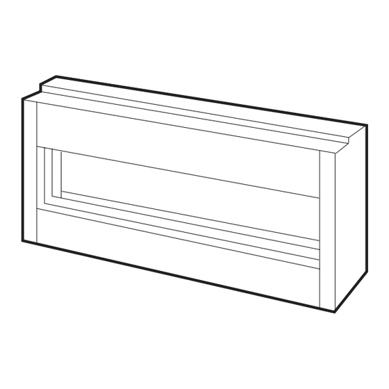
LANDSCAPE MODEL INTRODUCTION The Real Flame “Landscape” is a ribbon burner space heater for use with Natural Gas Aus & NZ and Propane. The Real Flame warranty will be voided by, and Real Flame disclaims any responsibility for the following actions: •... -
Page 7: Dimensions Landscape 1000
DIMENSIONS Landscape 1000 1000 1160 50mm Stand Offs 100mm Stand Offs 25mm Stand Offs Fixing channel for plaster Lifting Handles Trim 70mm 90mm Power Landscape 1000 Trim 1100... -
Page 8: Dimensions Landscape 1600
DIMENSIONS Landscape 1600 1600 1760 Trim Power Landscape 1600 Trim 1700... -
Page 9: Terminations
LANDSCAPE MODEL (continued) Cowl types • The Landscape is a balanced flue space heater. • It can be installed with the flue terminating with a horizontal or vertical cowl to suit the application. Vertical top Horizontal rear termination termination Vertical top RF/HZ termination Flue... -
Page 10: Timber Frame Installation
LANDSCAPE MODEL (continued) Timber Frame Installation Procedure Step 1 Construct the base for the unit. Ensure base is adequate for the weight of the fire. Step 2 Call for delivery of the unit, position on the base and fit off gather, flues and termination. Connect gas and power. - Page 11 LANDSCAPE MODEL (continued) Timber Frame Installation Procedure Step 3 Construct the frame around the fire as per drawing, taking note of required clearances. (See page 12) PLASTER Step 4 Sheet plaster and finish remembering to run plaster beyond stud and behind trim. TRIM Step 5 Commission fire as per...
- Page 12 LANDSCAPE MODEL (continued) Landscape 1000 & 1600 Timber Frame Installation Dimensions (Recommended only) FLUE GATHER VIEWING AREA* TRIM Plaster to run beyond stud and behind trim *Viewing area for 1000 is 1000mm x 370mm Viewing area for 1600 is 1600mm x 370mm Frameout Dimensions (in mm) NOTE: Ensure frame is suitable for fire weight.
-
Page 13: Vertical & Horizontal Venting Installation
LANDSCAPE ZERO CLEARANCE MODEL (continued) INSTALLATION OF VERTICAL & HORIZONTAL FLUING Vertical terminations must be installed with the following clearances: • Minimum of 500 mm from the nearest part of the roof (Measurement is taken from the bottom of the termination). •... -
Page 14: Tests To Be Carried Out By Installer
LANDSCAPE MODEL (continued) Tests to be carried out by installer • Check unit for gas leaks. • Ensure that both high and low pressures are set as per the appliance data plate on page 5. Refer to page 18 for adjustments and test pressure points •... -
Page 15: Logset Set Up
LANDSCAPE MODEL (continued) Set up for logsets in Landscape 1000 & 1600 1600 burner logplate 1000 burner logplate Logs and coals... - Page 16 LANDSCAPE MODEL (continued) Set up for logsets in Landscape 1000 Step 1 Step 2 Step 3 Step 4...
- Page 17 LANDSCAPE MODEL (continued) Set up for logsets in Landscape 1000 Step 5 Step 6 - Finished log assembly...
- Page 18 LANDSCAPE MODEL (continued) Set up for logsets in Landscape 1600 Step 1 Step 2 Step 3 Step 4...
- Page 19 LANDSCAPE MODEL (continued) Set up for logsets in Landscape 1600 Step 5 Step 6 - Finished log assembly...
-
Page 20: Servicing And Maintenance
SERVICING AND MAINTENANCE To follow when servicing, removing fan or changing valve or control modules. IMPORTANT: POWER MUST BE ISOLATED PRIOR TO CARRYING OUT THE SERVICE/MAINTENANCE. SERVICE/MAINTENANCE ONLY TO BE CARRIED OUT BY AN AUTHORISED PERSON. DO NOT MODIFY THIS APPLIANCE 1. - Page 21 SERVICING AND MAINTENANCE (continued) 8. Remove burner 9. Remove bottom of burner tray, fan is then exposed and may be serviced or removed To service or change gas valve or control modules, the After carrying out service or process is the same as steps replacing parts, reverse the 1 to 3.
-
Page 22: Parts List
PARTS LIST SIT 845 SIGMA GAS CONTROL VALVE SIT 579 ELECTRONIC FLAME CONTROL DEVICE MILLENIUM THERMOSTAT REMOTE CONTROL SYSTEM SIT PILOT ASSEMBLY 1. Pilot 2. Pilot Tube 3. Burner Tube... -
Page 23: Gas Control Assembly
GAS CONTROL ASSEMBLY Inlet Test Adjustment Outet Test Pressure Point for High Pressure Point Gas Inlet Gas Outlet Adjustment for Low... -
Page 24: Flue Termination (Cowls) Regulations
LANDSCAPE FLUE TERMINATION (COWLS) REGULATIONS Balanced Flue... -
Page 25: Remote Control Operating Guide
• The remote control and the controller are non-serviceable parts and if faulty should be returned to Real Flame Pty Ltd for replacement. Locating the remote The remote houses the thermostat that controls the heat output of the fire. When storing the... - Page 26 REMOTE CONTROL OPERATING GUIDE (continued) Manual mode Manual mode does not require that the time and day of the week are set. Press the L or M button to increase or decrease the temperature desired. Automatic mode The automatic mode allows the temperature to be regulated according to a programmed level and time.
- Page 27 REMOTE CONTROL OPERATING GUIDE (continued) Programming • Setting the period starting time The hour and AM/PM settings will now flash. To set the P1 starting time, press and release the L or M button to increase or decrease the hour setting. Press and hold the L or M button for 2 seconds or longer to increase or decrease the hour setting by 1 hour every 0.5 seconds.
-
Page 28: Electrical Diagram
ELECTRICAL DIAGRAM - Landscape 1000... - Page 29 ELECTRICAL DIAGRAM - Landscape 1600...
-
Page 30: Troubleshooting
IF YOUR LANDSCAPE FIREPLACE STILL DOES NOT OPERATE CORRECTLY CONSULT YOUR DEALER. ALL SERVICE AND REPAIRS SHOULD BE PERFORMED BY AN AUTHORISED AGENCY. ALL SPARE PARTS AND OPTIONAL TRIM FINISHES ARE AVAILABLE FROM REAL FLAME PTY LTD. -
Page 32: Real Flame Contact Information
REAL FLAME PTY LTD ABN 76 006 311 155 Head Office/Factory/Showroom 1340 Ferntree Gully Rd. Scoresby Vic 3179 Ph: (03) 8706 2000 Fax: (03) 8706 2001 E-mail: info@realflame.com.au Richmond - VIC Showroom 300 Swan St. Richmond Vic 3121 Ph: (03) 9428 4443 Fax: (03) 9428 4445...
Need help?
Do you have a question about the LANDSCAPE BALANCED and is the answer not in the manual?
Questions and answers