Real Flame ELEMENT 1200 Installation & Operating Manual
Flame effect space heater
Hide thumbs
Also See for ELEMENT 1200:
- Installation & operating manual (69 pages) ,
- Installation and operation manual (47 pages)
Table of Contents

Subscribe to Our Youtube Channel
Related Manuals for Real Flame ELEMENT 1200


Summary of Contents for Real Flame ELEMENT 1200
- Page 1 ELEMENT FLAME EFFECT SPACE HEATER INSTALLATION & OPERATING MANUAL The Real Flame Element space heater is suitable to be installed into a frame out installation. Designed to operate on Natural gas, LPG and ULPG gas. Approval no.GMK 10441 VERSION 16...
-
Page 2: Warranty Information
Date Of Purchase / settlement of property if new home _________________ Model / Serial Number_______________________ This warranty does not cover the cost of claiming under the warranty or transporting the Real Flame Gas Burner to and from the supplier. Our goods come with guarantees that cannot be excluded under the Australian Consumer Law. You are entitled to a replacement or refund for a major failure and for compensation for any other reasonably foreseeable loss or damage. - Page 3 WARNING The Element space heater has a primary safety glass fitted in front of the glass door. This safety glass is fitted to this appliance to reduce the risk of injury from burns and at no time should this glass be permanently removed.
-
Page 4: Table Of Contents
Standard 0-3m Flue - Wall mounted ..............15 Commissioning procedure ..................38 Media Installation....................39 Operation - User Instructions................43 Flue Termination (Cowls) ..................44 Remote Control Operating Guide .................45 Troubleshooting ....................56 Wiring Diagram .....................57 Conversion details ....................58 Parts List.......................66 Real Flame contact information ................72... -
Page 5: Dataplate
(Affixed to the base of the unit for reference to gas pressure & consumption) DATA PLATE MODEL ELEMENT 1200 INJECTOR SIZE N.G.C. (Mj/hr) GAS TYPE Natural Gas 3 X 2.25mm 0.85kPa High / 0.55kPa Low 37 High/29 Low 3 X 0.95mm 2.50kPa High / 1.70kPa Low... -
Page 6: Standard 0-3M Flue - Wall Mounted
ELEMENT STANDARD 0-3M FLUE - WALL MOUNTED FAN... -
Page 7: Installation Instructions
For flue configurations 3m or less run an aluminium flexible flue for both the inlet and outlet. Where lengths greater than 3m are required but less than 5m, use the ELEMENT 1200 XL IOM. Flue runs 3m or less (75mm diameter Aluminium flexi flue) Maximum flue runs 3m total length including 3 x 90°... - Page 8 (continued) INSTALLATION INSTRUCTIONS BALANCED FLUE TERMINATION LOCATION This section is used to determine where your Balanced Flue termination will be located. • Flue terminations shall not be recessed in walls or sidings. • EXTREMELY IMPORTANT: In heavy snow areas take extra care to prevent blocking flue termination with snow removal equipment.
- Page 9 (continued) INSTALLATION INSTRUCTIONS Wall mounted fan module – terminal must be installed with clearances as specified by AS5601.1 Clause 6.9.3 Run exhaust flue and air intake flue as required – Maximum run 3m. Flues can be run next to each other. Maintain clearances to combustibles. Connection to appliance Cut tube to length where required.
- Page 10 (continued) (continued) INSTALLATION INSTRUCTIONS INSTALLATION INSTRUCTIONS Slide flue onto connection spigot fully. Tighten clamp fully. Wipe excess silicon, visually check connection to ensure connection is fully sealed. Repeat above with air intake flue pipe to heater connection. Clip flues as required to provide adequate support.
- Page 11 (continued) INSTALLATION INSTRUCTIONS Remove wall mount plate from flue connection plate. Cut flue exhaust tube (hot tube) to length (Approximately flush with wall exit). Connection plate will sit against wall. Cut Air intake flue 70mm longer. Ensure ends are burr free and round, test fit flue will slide over connection.
- Page 12 (continued) INSTALLATION INSTRUCTIONS Feed air intake flue pipe through location spigot and fit retaining screw. Push connection plate into approximate position. Locate wall mounting bracket into position and affix to wall. Assemble spigot connection plate assembly to wall mounting bracket. (4 screws)
- Page 13 (continued) INSTALLATION INSTRUCTIONS Feed power cable through bottom area of bracket. Assemble main body assembly onto wall mounting bracket, feed power cable through grommet hole prior to fitting. (refit 5 screws as shown and tighten) Main body assembly must sit flush up against the mounting bracket and seal.
- Page 14 (continued) INSTALLATION INSTRUCTIONS Connect power cable connector. Fit cable clamp to cable. Fit front cover.
-
Page 15: Standard 0-3M Flue - Wall Mounted
ELEMENT STANDARD 0-3M FLUE - INTERNAL FAN... - Page 16 (continued) (continued) INSTALLATION INSTRUCTIONS INSTALLATION INSTRUCTIONS SETUP WITH INTERNAL FAN MODULE WITH WALL TERMINATION – APPLIANCE MOUNTED Maximum 3m flue length – total 3 bends Wall termination Wall terminal must be installed with clearances as specified by AS5601.1 Clause 6.9.3 Run exhaust flue and air intake flue as required –...
- Page 17 (continued) INSTALLATION INSTRUCTIONS Check 65mm flue piece for correct shape and fitment onto appliance spigot. Ensure ends are burr free and round, test fit flue will slide over connection. Recommended Silicon – Non-acetic, neutral cure 150degc or higher temperature rated. Bostik RTV 926 or similar.
- Page 18 (continued) INSTALLATION INSTRUCTIONS Fit 2nd flue clamp loosely onto the 65mm section of flue. Lift fan assembly into appliance and locate onto flue connection. Insert fully. Locate fan in the required direction. Screw fan assembly down onto the appliance. (Screws prefitted into holes are located on the appliance for direct out back connection and 90°...
- Page 19 (continued) INSTALLATION INSTRUCTIONS Apply an 8mm thick silicon bead fully around heater connection approx. 10mm from the top. Apply an 8mm silicon bead fully around the inside of the flue end (heater connection end) Fit flue clamp over flue (loosely). Slide flue onto connection spigot fully.
- Page 20 (continued) INSTALLATION INSTRUCTIONS Apply an 8mm thick silicon bead fully around heater connection approx. 10mm from the top. Apply an 8mm silicon bead fully around the inside of the flue end (heater connection end). Fit flue clamp over flue (loosely). Slide flue onto connection spigot fully.
- Page 21 (continued) INSTALLATION INSTRUCTIONS Connection to wall terminal LOOSE FIT CONNECTIONS (Wall termination connections) Locate terminal on wall and predrill mounting holes where required. Cut flue exhaust tube (hot tube) to length (Flue must extend a minimum of 50mm past the exit face of wall.) It is recommended that the tubes are cut slightly longer and pushed back into wall upon fixing of wall terminal.
- Page 22 (continued) INSTALLATION INSTRUCTIONS Feed air hot exhaust flue into connection, ensure inserted 50mm. Fit retaining screw from below. Feed air intake flue into connection, ensure inserted 50mm. Fit retaining screw from below. Push terminal into approximate position and affix onto wall.
- Page 23 (continued) INSTALLATION INSTRUCTIONS SETUP WITH INTERNAL FAN MODULE WITH WALL TERMINATION – MID FLUE MOUNTED Maximum 3m flue length – total 3 bends (Intake flue- 4 bends allowed) Wall termination - same as appliance mounted wall termination Wall terminal must be installed with clearances as specified by AS5601.1 Clause 6.9.3 Run exhaust flue and air intake flue as required –...
- Page 24 (continued) INSTALLATION INSTRUCTIONS Cut flue to length to suit connection. Ensure ends are burr free and round, test fit flue will fit over connection. Apply an 8mm thick silicon bead fully around heater connection approx. 10mm from the top. Apply an 8mm silicon bead fully around the inside of the flue end (heater connection end) Fit flue clamp over flue (loosely).
- Page 25 (continued) INSTALLATION INSTRUCTIONS Repeat for connection to underside of fan module. Repeat for Air intake flue connection. Fan module outlet connection Cut tube to length where required. Ensure ends are burr free and round, test fit flue will slide over connection. Apply an 8mm thick silicon bead fully around heater connection approx.
- Page 26 (continued) INSTALLATION INSTRUCTIONS Slide flue onto connection spigot fully. Tighten clamp fully. Wipe excess silicon, visually check connection to ensure connection is fully sealed. Connect power lead to fan module. Ensure lead is clipped to support where required. Do not use connection to support lead. Connection to wall terminal LOOSE FIT CONNECTIONS (Wall termination connections)
- Page 27 (continued) INSTALLATION INSTRUCTIONS Locate terminal on wall and predrill mounting holes where required. Cut flue exhaust tube (hot tube) to length (Flue must extend a minimum of 50mm past the exit face of wall.) It is recommended that the tubes are cut slightly longer and pushed back into wall upon fixing of wall terminal.
- Page 28 (continued) INSTALLATION INSTRUCTIONS Push terminal into approximate position and affix onto wall. SETUP WITH INTERNAL FAN MODULE WITH ROOTOP TERMINATION – MID FLUE MOUNTED Maximum 3m flue length – total 3 bends (Intake flue- 4 bends allowed) Note – fan module can be appliance mounted or mid mounted when finishing with the rooftop termination.
- Page 29 (continued) INSTALLATION INSTRUCTIONS Rooftop termination must be installed with clearances as specified by AS5601.1 Run exhaust flue and air intake flue as required – Maximum total run 3m per flue. Flues can be run next to each other. Maintain clearances to combustibles. Mount fan controller in the required location.
- Page 30 (continued) INSTALLATION INSTRUCTIONS Apply an 8mm thick silicon bead fully around heater connection approx. 10mm from the top. Apply an 8mm silicon bead fully around the inside of the flue end (heater connection end) Fit flue clamp over flue (loosely). Slide flue onto connection spigot fully.
- Page 31 (continued) INSTALLATION INSTRUCTIONS Repeat for connection to underside of fan module. Repeat for Air intake flue connection. Fan module outlet connection Cut tube to length where required. Ensure ends are burr free and round, test fit flue will slide over connection. Apply an 8mm thick silicon bead fully around heater connection approx.
- Page 32 (continued) INSTALLATION INSTRUCTIONS Slide flue onto connection spigot fully. Tighten clamp fully. Wipe excess silicon, visually check connection to ensure connection is fully sealed. Connect power lead to fan module. Ensure lead is clipped to support where required. Do not use connection to support lead. Connection to rooftop terminal Prepare roof penetration.
- Page 33 (continued) INSTALLATION INSTRUCTIONS Cut rooftop penetration to length if required. Install into roof penetration. Install supports for base of penetration kit Connect hot exhaust flue and air intake flue as per below. Apply an 8mm silicon bead fully around the inside of the flue end.
- Page 34 (continued) INSTALLATION INSTRUCTIONS Fit roof sealing method. (Decktite or similar) Fit rooftop cowl. Screw or rivet in 3 places to hold into place. Ensure flue is supported and clipped where required.
-
Page 35: Timber Frame Installation
TIMBER FRAME INSTALLATION 50mm trim only Plaster to run beyond stud and behind trim Frameout Dimensions (in mm) 1420... - Page 36 (continued) TIMBER FRAME INSTALLATION APPLIANCE MOUNTED FLUE FAN (FITTED WITH FAN ACCESS TRIM) BB trim only Plaster to run beyond stud and behind trim Frameout Dimensions (in mm) 1420...
- Page 37 TIMBER FRAME INSTALLATION 18mm Trim 1. Install Element 1200 onto base and connect flue, gas and power. 2. Fit 18mm trim frame. 3. Locate 4 sided flange kit. 4. Remove 18mm frame. 5. Clad wall to flange kit and finish.
-
Page 38: Commissioning Procedure
COMMISSIONING PROCEDURE 50mm trim 18mm trim flange kit 405 552 1208 1354 18mm low profile trim BB trim (provides access to flue motor) -
Page 39: Media Installation
Do not add extra media, or combine media types. • Only the approved supplied media is to be used. • Refer to Real Flame for technical advice regarding media. • Do not cover pilot area. • Do not overfill with media above the pilot cover level. - Page 40 (continued) MEDIA INSTALLATION Coals only • Lay coal media in a random arrangement along the entire length of the burner. • Avoid smothering the burner channel. Apply coals either side of the flame channel. • No more than 4 coals should cover the main flame channel. •...
- Page 41 (continued) MEDIA INSTALLATION Logs and Coals • Lay coal media in a random arrangement along the entire length of the burner. • Avoid smothering the burner channel. Apply coals either side of the flame channel. • Ensure media is not heaped in areas, spread evenly along. •...
- Page 42 Do not add extra media, or combine media types. • Only the approved supplied media is to be used. • Refer to Real Flame for technical advice regarding media. • Do not cover pilot area. • Do not overfill with media above the pilot cover level.
-
Page 43: Operation - User Instructions
OPERATION – USER INSTRUCTIONS • Do not operate if you smell gas. Turn appliance off, extinguish any open flame. Contact your installer or a licensed gasfitter. • Do not use if any part of this appliance has been submerged in water. Contact your installer or a qualified service technician. -
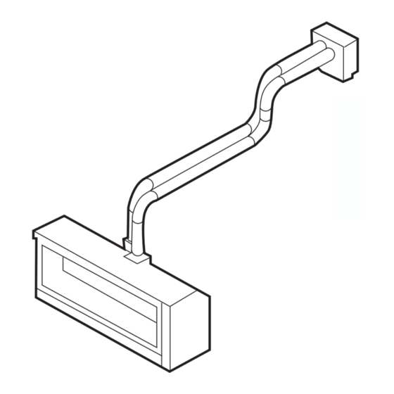
Page 44: Flue Termination (Cowls)
ELEMENT 1200 FLUE TERMINATION (COWLS) Balanced Flue... -
Page 45: Remote Control Operating Guide
REMOTE CONTROL OPERATING GUIDE The Element 1200 is controlled completely by the use of the remote control; this remote can be used either as a manual operation or an auto operation. • The remote thermostat uses radio frequency to transmit to the gas/fan controller. - Page 46 (continued) REMOTE CONTROL OPERATING GUIDE Manual mode Manual mode does not require that the time and day of the week are set. Press the or t button to increase or decrease the temperature desired. Automatic mode The automatic mode allows the temperature to be regulated according to a programmed level and time.
- Page 47 (continued) REMOTE CONTROL OPERATING GUIDE Programming • Setting the period starting time The hour and AM/PM settings will now flash. To set the P1 starting time, press and release or t button to increase or decrease the hour setting. Press and hold the or t button for 2 seconds or longer to increase or decrease the hour setting by 1 hour every 0.5 seconds.
- Page 48 Note: The programming function is only done via the remote control. Introduction These pages outline the Operation of the Real Flame MKII Thermostat system. The System Includes 1. Real Flame Modulating Valve MKII update 2. Real Flame WiFi Interface MKII 3.
- Page 49 (continued) WIFI DEVICE CONTROL INSTRUCTIONS Step by Step – Pushing the Fireplace to a local network Illustration 1: Open up the settings Illustration 2: Select the Access Screen and select the Wi-Fi option point for your Fireplace Illustration 3: Enter the default Illustration 4: Check the password for your Fireplace AP connection status for the Fireplace...
- Page 50 (continued) WIFI DEVICE CONTROL INSTRUCTIONS Step by Step – Pushing the Fireplace to a local network Illustration 5: Open the Fireplace Illustration 6: When prompted, select 'Connect to Network' Illustration 7: Select the Network Illustration 8: The App will start to you want to use search for the device on the network...
- Page 51 (continued) WIFI DEVICE CONTROL INSTRUCTIONS Step by Step – Pushing the Fireplace to a local network Illustration 9: You can now control your Fireplace from the network you are connected to.
- Page 52 (continued) WIFI DEVICE CONTROL INSTRUCTIONS Internet Control If your model supports Internet control, upon using the App after being pushed to a local or home network with internet, the application will prompt you to set up the network features. Set-up Selecting Yes will take you to the Registration requires: sign up screen...
- Page 53 (continued) WIFI DEVICE CONTROL INSTRUCTIONS Step by Step – Pushing the Fireplace to a local network User Added Successfully, your Fireplace is now linked to your account, you can control your Fireplace by logging into the application when prompted Operation When on another network or using your Mobile data, launching the App will present you with the log in screen.
- Page 54 (continued) WIFI DEVICE CONTROL INSTRUCTIONS Pushing the Fireplace to a different home or local network after initial install Pushing the Fireplace to a different home or local network after it has previously been set up, is done at Fireplace power on, when the fireplace is powered off at the Main switch, upon being powered on, the Fireplace will show its Access point (Realflame_XXXXXX) for 30 seconds.
- Page 55 (continued) WIFI DEVICE CONTROL INSTRUCTIONS AUTO MODE - Only available via the remote.
-
Page 56: Troubleshooting
IF YOUR FIREPLACE STILL DOES NOT OPERATE CORRECTLY CONSULT YOUR DEALER. ALL SERVICE AND REPAIRS SHOULD BE PERFORMED BY AN AUTHORISED AGENCY. ALL SPARE PARTS AND OPTIONAL TRIM FINISHES ARE AVAILABLE FROM REAL FLAME PTY LTD. -
Page 57: Wiring Diagram
WIRING DIAGRAM... -
Page 58: Conversion Details
CONVERSION INSTRUCTIONS Natural gas / Propane / ULPG. 10mm spanner TOOLS 15mm spanner 16mm Spanner (recommended) or small/medium shifter No2 Phillip head screwdriver Allen key 2.5mmAF Turn appliance and allow to cool. BURNER Turn off gas to appliance Turn off and isolate appliance from electrical supply Remove trim screws (2 off) Remove trim (Slides out) - Page 59 (continued) CONVERSION INSTRUCTIONS Remove lower access panel. Remove door screws (10 off) Lift off door (Ensure door is cool before attempting) Remove media where fitted. 10/ Remove end cover plate screw and lift out end plate. (LH and RH end)
- Page 60 (continued) CONVERSION INSTRUCTIONS 11/ Remove burner fixing screws ( 2 off at ends of burner). 12/ Lift burner up and gently support. 13/ Undo gas connection pipe at end of burner. (15mm and 16mm spanner required)
- Page 61 (continued) CONVERSION INSTRUCTIONS 14/ Lift burner out gently. Avoid marking back wall. Keep burner in the flat position until insulation is restrained (Rotating the burner may cause insulation to fall and be damaged. 15/ RECOMMENDED STEP To avoid damage to the insulation apply low tack tape to the burner to restrain the insulation into position.
- Page 62 (continued) CONVERSION INSTRUCTIONS 18/ Undo grub screw (Allen key 2.5mm AF). Injector assembly can now be removed. 19/ Remove all injector assemblies. Unscrew injector and replace with correct gas type. 20/ Loosen aeration cap screw approx. ½ turn. Rotate cap until the correct gap is achieved to suit the gas type.
- Page 63 (continued) CONVERSION INSTRUCTIONS 21/ Refit injector assembly into aeration cap. 22/ Refit gas pipe and tighten nuts. 23/ Ensure injector assembly is sitting firmly into aeration cap and tighten grub screw. NOTE – ENSURE INJECTOR ASEMBLY IS AIMING CENTRALLY INTO THE AERATION CAP AND TUBE Correct where required.
- Page 64 (continued) CONVERSION INSTRUCTIONS Remove pilot bracket holding screw. PILOT Gently lift pilot assembly up to enable access to pipe fittings. Remove spark lead Remove spark probe (10mm spanner required)
- Page 65 (continued) CONVERSION INSTRUCTIONS Remove pilot pipe fitting from pilot assembly. Remove pilot orifice from pilot or replace whole pilot assembly with correct gas type. Replace pilot orifice with correct gas type. PILOT REFITMENT Refit pilot gas pipe and tighten Refit spark probe and gently tightly Refit spark lead Push pilot assembly down to original position and refit the bracket retaining screw.
- Page 66 (continued) CONVERSION INSTRUCTIONS Check all wires are sitting correctly, flush to front wall. Ensure spark lead is not broken or excessively bent. Ensure lead hole is still sealed. (High temperature silicon is suitable for resealing.) Carefully place burner into firebox, supporting BURNER REFITMENT LH end of the burner.
- Page 67 (continued) CONVERSION INSTRUCTIONS Fit manometer to appliance. Start appliance and check for gas leaks in lower area and in firebox. Adjust high and low burner pressures to the dataplate. (The appliance must operate for 3minutes before high pressure setting can be obtained).
-
Page 68: Parts List
PARTS LIST Valve SIT Pilot assembly Natural gas SIT Pilot assembly Propane Injector Natural gas Injector LPG - ULPG Millennium receiver (Element) Millennium remote control (Element) Sit Ignition pack / gas control... -
Page 72: Real Flame Contact Information
GLEN DIMPLEX AUSTRALIA PTY LTD ABN 69 118 275 460 Head Office/Factory/Showroom 1340 Ferntree Gully Rd. Scoresby Vic 3179 Ph: (03) 8706 2000 Fax: (03) 8706 2001 E-mail: info@realflame.com.au Richmond - VIC Showroom 300 Swan St. Richmond Vic 3121 Ph: (03) 9428 4443 Fax: (03) 9428 4445 Dandenong - VIC Showroom 3/328 South Gippsland Highway, Dandenong South Vic 3164...
Need help?
Do you have a question about the ELEMENT 1200 and is the answer not in the manual?
Questions and answers