Table of Contents
Advertisement
Quick Links
Advertisement
Table of Contents

Related Manuals for Real Flame Captiva Island


Summary of Contents for Real Flame Captiva Island
- Page 1 BALANCED FLUE SPACE HEATER INSTALLATION & OPERATING MANUAL The Captiva Island gas fire is approved to be installed as a zero clearance firebox and are designed to operate on Natural Gas and Propane (LPG) gases ONLY. Approval Number GMK10060. VERSION 9...
-
Page 2: Warranty Information
(www.realflame.com.au) or completing and mailing the attached registration card within 30 days of purchase of your Real Flame Gas Burner (or, if the Real Flame Gas Burner is fitted to a new home, within 30 days of the date of settlement of purchase of such new home). - Page 3 WARNING The “Captiva Island” has a primary safety glass fitted in front of the inner glass panels. This safety glass is fitted to the appliance to reduce the risk of injury from burns and at no time should this glass be permanently removed.
-
Page 4: Table Of Contents
Dimensions 3 sided ....................8 Timber frame installation..................9 Fluing options ......................11 Ceramic set up and installation procedures............12 Servicing and maintenance ...................14 Parts list ........................18 Flue termination (cowls) regulations ..............19 Remote control operating guide ................20 Electrical diagram ....................23 Real Flame contact information ................24... -
Page 5: Data Plate
DATA PLATE (Affixed to the base of the unit for reference to gas pressure & consumption) MODEL CAPTIVA ISLAND SERIAL NO. DATE OF MANUFACTURE GAS TYPE APPROVAL: GMK10060 NATURAL GAS @ 0.95 kPa Test Pressure Point (High) Injector Size Gas Consumption 2 x 2.55 mm... -
Page 6: Zero Clearance Introduction
CAPTIVA ISLAND ZERO CLEARANCE MODEL INTRODUCTION The Real Flame “Captiva Island” is a log/coal or pebble effect space heater for use with Natural Gas and Propane. The Real Flame warranty will be voided by, and Real Flame disclaims any responsibility for the following actions: •... -
Page 7: Dimensions 2 Sided
DIMENSIONS SIDED Captiva Island 2 sided 1:20 1100 Captiva Island 2 sided trim... -
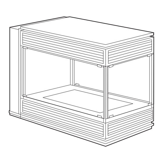
Page 8: Dimensions 3 Sided
DIMENSIONS SIDED Captiva Island 3 sided 1:20 1100 Captiva Island 3 sided trim SIDE x 2... -
Page 9: Timber Frame Installation
Zero Clearance cowl types • The Captiva Island balanced flue space heater is a zero clearance type heater which comes complete in a zero clearance casing. • The flue can terminate horizontally or vertically. Vertical top... - Page 10 CAPTIVA ISLAND FRAME DETAIL Timber Frame Installation IMPORTANT Install unit and fluing before NOTE: Plaster to run beyond stud plasterboard. and behind trim FIRE FIRE 2 sided 3 sided Model 1000 1225 2 sided 1000 1150 3 sided * Note: The “C” dimension is the finished depth including cladding.
-
Page 11: Fluing Options
ISLAND ZERO CLEARANCE MODEL (continued) INSTALLATION OF VERTICAL VENTING Vertical terminations must be installed with the following clearances: • Minimum of 500 mm from the nearest part of the roof (Measurement is taken from the bottom of the termination). • Minimum of 1500 mm from any mechanical air inlet. -
Page 12: Ceramic Set Up And Installation Procedures
CAPTIVA ISLAND ZERO CLEARANCE MODEL (continued) Captiva Island Fire Installation Procedure TICK BOXES Locate fire into frameout as per page 10 Connect to gas supply and check for leaks Connect to power supply Install flue as per directions on page 11... - Page 13 CAPTIVA ISLAND ZERO CLEARANCE MODEL (continued) (continued) Captiva Island Fire Installation Procedure PEBBLE OPTION To install pebbles follow the instructions below taking care not to place the pebbles over the burner rail. Figure (1) Place the 12 large pebbles into the Figure (2) Add the 16 medium pebbles as burner as shown.
-
Page 14: Servicing And Maintenance
SERVICING AND MAINTENANCE IT IS RECOMMENDED THAT YOUR HEATER BE SERVICED AT LEAST EVERY TWO YEARS BY A QUALIFIED TRADESMAN. To follow when servicing, removing fan or changing valve or control modules. IMPORTANT: POWER MUST BE ISOLATED PRIOR TO CARRYING OUT THE SERVICE/MAINTENANCE. - Page 15 SERVICING AND MAINTENANCE (continued) Figure (6) Now remove the stainless steel Figure (7) Loosen the top and bottom screws corner section by removing two screws from on the inner glass frames. Do end glass if 3 top and two from bottom. sided model.
- Page 16 SERVICING AND MAINTENANCE (continued) Figure (12) To remove the gas valve Figure (13) Remove all wires and undo disconnect the main gas pipe from the left screws from both fixing brackets. Remove side and the burner pipe from the right. valve.
- Page 17 Prior to lighting ensure there are no gas leaks. If your Captiva Island fireplace still does not operate correctly, consult your dealer. All service and repairs should be performed by an authorised person or company. All spare parts and optional trim finishes are available from Real Flame Pty Ltd.
-
Page 18: Parts List
PARTS LIST Gas Control Valve Module Box Remote Control Remote Control Module Sensor GAS CONTROL ASSEMBLY Inlet Test Adjustment Outet Test Pressure Point for High Pressure Point Gas Inlet Gas Outlet Adjustment for Low... -
Page 19: Flue Termination (Cowls) Regulations
CAPTIVA ISLAND FLUE TERMINATION (COWLS) REGULATIONS Balanced Flue... -
Page 20: Remote Control Operating Guide
• The remote control and the controller are non-serviceable parts and if faulty should be returned to Real Flame Pty Ltd for replacement. Locating the remote The remote houses the thermostat that controls the heat output of the fire. When storing the... - Page 21 REMOTE CONTROL OPERATING GUIDE (continued) Teaching RF code • Ensure the power to the heater is turned off. • Press in sequence <P>, <T>, <T>, <UP> • The LCD diplay will show “CL ” (Code Learn) for 2 seconds then return to the normal OFF state display.
- Page 22 REMOTE CONTROL OPERATING GUIDE (continued) In Auto mode, the RF thermostat will control the flame and the fan according to the programmed times and temperature. The flame can be programmed to turn on or off, or change the required temperature. The switch off and on sequence operate as per manual operation, detailed above.
-
Page 23: Electrical Diagram
ELECTRICAL DIAGRAM BLUE ORANGE BROWN... -
Page 24: Real Flame Contact Information
CHEMINEE PTY LTD EMAIL sales@cheminee.com.au WEBSITE www.Cheminee.com.au PHONE 02 9564 2694 FAX 02 9569 8802 SHOWROOM 118 Stanmore Road, Stanmore (Corner Wemyss St) NSW...
Need help?
Do you have a question about the Captiva Island and is the answer not in the manual?
Questions and answers