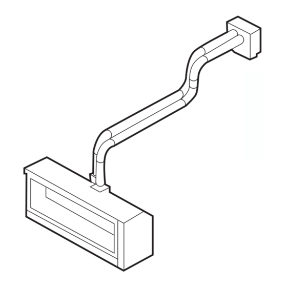
Real Flame ELEMENT 1200 Installation And Operation Manual

Real Flame ELEMENT 1200 Installation And Operation Manual

Double sided
Hide thumbs Also See for ELEMENT 1200:

Advertisement

Quick Links

E L E M E N T 12 0 0 & 18 0 0 D O U B L E S I D E D
S P A C E H E A T E R S
I N S T A L L A T I O N A N D O P E R A T I O N I N G M A N U A L
The Element 1200 & 1800 Double Sided space heaters are suitable to be installed into a frame out
installation. Designed to operate on Natural gas and LPG
Approval no.GMK 10441
Consumer safety information: please read this manual before installing and operating this appliance.
Failure to follow these instructions may result in a possible fire hazard and/or injury and will void the
warranty.
Ve rsi on 10

Advertisement

Table of Contents
loading
Need help?

Need help?

Do you have a question about the ELEMENT 1200 and is the answer not in the manual?

Questions and answers

Subscribe to Our Youtube Channel

Summary of Contents for Real Flame ELEMENT 1200

  • Page 1 I N S T A L L A T I O N A N D O P E R A T I O N I N G M A N U A L The Element 1200 & 1800 Double Sided space heaters are suitable to be installed into a frame out installation.
  • Page 2: Table Of Contents

    C O N T E N T S W ELCO ME SPECI FI CAT I ONS O P E R A T I O N I N S T R U C T I O N S USER I NSTR UC T IONS W iFi D E VI CE CON TROL IN STRUCTI ONS T R O UB L E S H OOT IN G F OR YOUR FIREPLACE I N S T A L L A T I O N I N S T R U C T I O N S...
  • Page 3: W Elco Me

    W E L C O M E Congratulations on your selection of the stunning Real Flame Double Sided Fireplace. Enjoy double the viewing pleasure, delivered with combined clean lines and cutting-edge design to present a truly stunning fireplace. We hope you create endless memories infront of this warm and cosy fireplace.
  • Page 4: Speci Fi Cat I Ons

    S P E C I F I C A T I O N S O F 12 0 0 D S Appliance Type High Efficiency Gas Fireplace Star Rating Up to 4.3 stars Maximum Heating Output Up to 7.4kW Heats Room up to 100m²...
  • Page 5 S P E C I F I C A T I O N S O F 18 0 0 D S Appliance Type High Efficiency Gas Fireplace Star Rating Up to 4.6 stars Maximum Heating Output Up to 9kW Heats Room up to 120m²...
  • Page 6: O P E R A T I O N I N S T R U C T I O N S

    O P E R A T I O N I N S T R U C T I O N S Page...
  • Page 7: User I Nstr Uc T Ions

    RE MOTE C ON TR OL G UID E from the fire. The Element 1200 and 1800 DS are controlled completely • Appliance operates with luminous flames; carbon by the use of the remote control; this remote can be used deposits may occur during operation.
  • Page 8 • The fan will automatically come on after the fire has that period’s setting. been operating for 3 minutes 20 seconds. P ro gram mi ng • When the fire shuts off on auto mode or is shut off in Each day of the week can be programmed individually manual mode, the fan will continue to operate for 8 for 4 periods P1, P2, P3 and P4, making a total of 28...
  • Page 9 Press ‘OK’ to accept. • The minimum temperature should be set at a The minute setting will now flash. Adjust the minute setting temperature that is not likely to cause the fire to similarly, using button. continually turn on and off. Press ‘OK’...
  • Page 10: W Ifi D E Vi Ce Con Trol In Structi Ons

    WiFi module St ep 2 connected. Download the Real Flame Fire MKII App from the App store or play store if you’re an Android user. W iF i S et -u p From Factory settings the Fireplace will broadcast an...
  • Page 11 S te p 3 St ep 5 Open the App and click on Set up if you are a new user and have not Go to the WiFi setting on your phone and select your fireplace when established connection to your fireplace prior to this. the device prompts you to choose a network.
  • Page 12 St ep 7 S tep 9 Once the fireplace is connected click on the information button and Congrats you have connected to the fireplace. Sit back, relax and select auto join for ease of connection in the future. increase or decrease the temperature as you please. S te p 8 S tep 10 Open the App and click on NO when this pops up.
  • Page 13 S e t t i n g re m o t e a c c e ss S te p 11 f i re p l a c e Click OK when the option to rename appears and input the new (eg: Using the phone or tablet remotely to activate the fire when not name.
  • Page 14 S te p 14 S tep 15 Subject to operating system the following should occur - Once the Clicking Yes will open the registration section which once completed connection is established, the system will transport you to the screen will allow you to access your fireplace from anywhere. Put in the below.
  • Page 15 P u sh i n g t he Fi re p l a c e t o a di f f e re n t St ep 17 ho m e or l o c a l n e t wo rk a f t e r i n i ti a l Using device turn off fireplace.
  • Page 16: T R O Ub L E S H Oot In G F Or Your Fireplace

    T R O U B L E S H O O T I N G F O R Y O U R F I R E P L A C E P rob le m Possi bl e Cause Sugg ested Solution When the remote is activated nothing 1200 models - gas supply is turned Reprogram the remote to the receiver...
  • Page 17: I N S T A L L A T I O N I N S T R U C T I O N S

    I N S T A L L A T I O N I N S T R U C T I O N S Page...
  • Page 18: Uni T D I Me Ns Ions

    U N I T D I M E N S I O N S F- excl. clearance standoffs E- incl. clearance standoffs Flue Connections incl. clearance standoffs Frameless Trim Depth excl. clearance Power and Gas standoffs Connection UNIT 1200DS 1520 1470 1293 1 14 1800DS...
  • Page 19: Mini M Um Fra Me Out Di Me Nsi On S

    M I N I M U M F R A M E O U T D I M E N S I O N S 1- Minimum timber frame dimension. Once UNIT 10mm plasterboard is added on both sides, this will lead to the frameless trim protruding 1200DS 1595 by approx.
  • Page 20: In Stal L Ati O N I Nstr Uc T Ion S

    I N S T A L L A T I O N I N S T R U C T I O N S LO C AT IO N F LU E C O NF IG U RAT IO NS Select a location where the fire can be supervised during Flue configurations 5m or less run an aluminium flexible operation.
  • Page 21 affected. • Do not place, build any obstruction, plant any bushes or for any reason attempt to conceal the flue termination. To do so will affect the operation of the fireplace and may be hazardous. • This unit must always vent directly to outdoors. Page...
  • Page 22: Exte R N Al Wall Moun Te D Fa N Module Installat Ion

    E X T E R N A L W A L L M O U N T E D F A N M O D U L E I N S T A L L A T I O N Apply an 8mm silicon bead fully around the inside of the flue end...
  • Page 23 Slide flue onto connection Cut flue exhaust tube spigot fully. Tighten clamp (hot tube) length fully. (Approximately flush with wall exit). Connection Wipe excess silicon, plate will sit against wall. visually check connection to ensure connection is Cut Air intake flue. fully sealed.
  • Page 24: 5M Flue - Inl In E Fan M Odule

    0 M - 5 M F L U E – I N L I N E F A N M O D U L E S e t u p w it h i nt ern al fa n mod ule with w al l te r m i n at i on –...
  • Page 25 6. Connect power lead to fan module. Ensure lead is clipped Repeat for air intake flue support where connection. required. Do not use connection to support lead. 5. Fan module outlet connection 7. Connection to wall terminal Cut tube to length where Loose fit connections (wall termination connections) required.
  • Page 26 Locate terminal on wall and predrill mounting holes where required. Cut flue exhaust tube (hot tube) to length (Flue must extend a minimum of 50mm past the exit face of wall.) It is recommended that the tubes are cut slightly longer and pushed back into wall upon fixing of wall terminal.
  • Page 27 Run flue from appliance Se t u p wi t h i nt erna l i nl in e f an module w i th to bottom entry on fan ro o f t o p t erm i na tion – mi d fl ue mo unte d module.
  • Page 28 Slide flue onto connection spigot fully. Tighten clamp fully. Wipe excess silicon, visually check connection to ensure connection is fully sealed. Repeat for connection to underside of fan module. 5. Connect power lead to fan module. Ensure lead is clipped Repeat for air intake flue support where...
  • Page 29 Connect hot exhaust flue and air intake flue as per below. Apply an 8mm silicon bead fully around the inside of the flue end Fit flue clamp over flue (loosely). Air Intake Connection Flue Discharge Connection Slide flue onto connection spigot fully. Tighten clamp fully.
  • Page 30: Com M I Ss I O Ni Ng Pr Oce Dure

    C O M M I S S I O N I N G P R O C E D U R E O n c e t he f ire is i nst a ll ed : 1. Check for gas leaks. 2.
  • Page 31: Do Or R E Moval A Nd F It M E Nt

    D O O R R E M O V A L A N D F I T M E N T D o o r rem ova l (re commen de d 2 p erso n s) Using 2 people lift door carefully, supporting both the glass and frame.
  • Page 32: Med I A I Nsta Llat Ion

    M E D I A I N S T A L L A T I O N P L E AS E NOTE: not all media options shown are available for sale. Refer to glen dimplex australia for available options. G E N ER AL I NSTAL L ATIO N NOT E Lay media in a random arrangement along the entire length of the burner.
  • Page 33 D ri f t wo od w it h black diamond Red g um with b lac k diam ond glass gl as s (1200DS, 1800DS) (1200DS, 1800DS) • Spread glass pebbles out over the media support • Spread pebbles over the media support tray, ensure tray, ensure no coals are on the inside of the media no pebbles are inside the media retainer area and retainer area and the burner channel.
  • Page 34 Peb b le s wit h black diam o nd gla ss (Mix ed, G re y, Whi te a nd B l a c k) (1200DS and 1800DS) • Spread glass pebbles over the media support tray, ensure no pebbles are inside the media retainer area and the burner channel.
  • Page 35: Meas Ur I Ng B U Rne R T E St P Oi N T Pressure

    M E A S U R I N G B U R N E R T E S T P O I N T P R E S S U R E The appliance is supplied with a burner pressure test point located under the lower trim on the gas valve side. Remove lower trim to access.
  • Page 36: Con Ver Si O N De Tai Ls

    C O N V E R S I O N D E T A I L S / I N J E C T O R – P I L O T A N D B U R N E R R E M O V A L N at u ra l ga s / P rop a ne 15.
  • Page 37 28. Remove injectors from burner. Turn burner over gently. AVOIDING DAMAGING THE INSULATION.2 9. 29. Loosen gas pipe nuts form injectors and move gas pipe away. Note – 15mm spanner required for the nuts, a shifter or spanner should be used to support the brass injector assembly.
  • Page 38 The insulation media can be repainted using an approved Note - A ruler or similar high temperature paint, contact Glen Dimplex for details. can be used to check the opening, a drill bit of the 40. Refit burner designated size can also 41.
  • Page 39 50. Check for correct pilot flame and good cross lighting. 51. Pilot flame should be easily travelling over the burner Good Flame Colour channel. 52. Start appliance and adjust burner pressure to correct pressure. – Note wait 3 minutes for burner to automatically goto high setting.
  • Page 40: Par Ts L I St

    P A R T S L I S T Pa r ts P i c t u re Valve SIT Pilot assembly- refer gas type Injector Natural gas- refer gas type Millenium receiver Millennium remote control Techrite Ignition pack/gas control Page...
  • Page 41: App E Nd I X 1- F Lu E T E Rmin At Ion

    A P P E N D I X 1 - F L U E T E R M I N A T I O N Page...
  • Page 42: App E Nd I X 2- Wiri Ng Diag Ra M S

    A P P E N D I X 2 - W I R I N G D I A G R A M S 1200DS 1800DS Page...
  • Page 43: App E Nd I X 3- Addit Iona L M E Di A

    A P P E N D I X 3 - A D D I T I O N A L M E D I A Aeration Settings 1800DS Media Setup Available for sale Natural Gas Driftwood with Small Coals 2.0 / 4.0 / 4.0mm RH end Not Available Forest Floor with black diamond glass 1.5 / 2.5 / 2.5mm RH end...
  • Page 44 Fore st F loor w it h blac k diamond Dr if t wood wit h sma ll ceramic gl as s c oa ls (1800DS NG and LPG) (1800DS NG and LPG) • Spread glass shards over the media support tray, •...
  • Page 45 Red g um wi th L arge C o als Bla ck Dia mond Gla ss (1800DS NG only) (1800DS NG only) • Spread coals over the media support tray, ensure • Spread glass pebbles over the media support tray, no coals are inside the media retainer area and the ensure no pebbles are inside the media retainer area burner channel.
  • Page 46: War R An T Y I Nf Ormat I On

    W A R R A N T Y I N F O R M A T I O N The benefits provided to you under the following warranty are in Supplier Name___________________________________ addition to any other rights and remedies available to you under the law.
  • Page 47 Re a l Fla m e Au s trali a www.realflame.com.au 1300 554 155 Re a l Fl a m e N e w Ze ala nd www.realflame.co.nz 0800 666 2824 Page...

This manual is also suitable for:

Element 1800Element 1200dsElement 1800ds

Table of Contents