Real Flame Captiva 600 Installation & Operating Manual
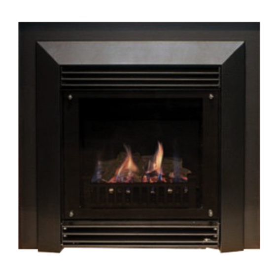
Captiva balanced
flue space heater
Hide thumbs
Also See for Captiva 600:
- Installation & operating manual (24 pages) ,
- Installation & operating manual (24 pages)
Table of Contents
Advertisement
Quick Links
Advertisement
Table of Contents

Subscribe to Our Youtube Channel
Related Manuals for Real Flame Captiva 600


Summary of Contents for Real Flame Captiva 600
- Page 1 BALANCED FLUE SPACE HEATER INSTALLATION & OPERATING MANUAL The Captiva 600 & 900 are approved to be installed as a zero clearance firebox and are designed to operate on Natural Gas and Propane (LPG) gases ONLY. Approval Number GSCS20081. VERSION 28...
-
Page 2: Warranty Information
(www.realflame.com.au) or completing and mailing the attached registration card within 30 days of purchase of your Real Flame Gas Burner (or, if the Real Flame Gas Burner is fitted to a new home, within 30 days of the date of settlement of purchase of such new home). - Page 3 WARNING The “Captiva 600 & 900” have a primary safety glass fitted in front of the glass door. This safety glass is fitted to these appliances to reduce the risk of injury from burns and at no time should this glass be permanently removed.
-
Page 4: Table Of Contents
CONTENTS Contents ........................4 Data Plate .........................5 Zero Clearance introduction ..................6 Installation Procedure ....................7 Dimensions Captiva 600 ..................9 Dimensions Captiva 900 ..................10 Timber frame installation..................11 Vertical venting installation..................13 Tests to be carried out by installer .................14 Servicing and maintenance ...................14 Parts list ........................16 Gas control assembly ....................16... -
Page 5: Data Plate
DATA PLATE (Affixed to the base of the unit for reference to gas pressure & consumption) MODEL CAPTIVA 600 SERIAL NO. DATE OF MANUFACTURE GAS TYPE APPROVAL: GSCS20081 NATURAL GAS @ 1.00 kPa Test Pressure Point (High) Injector Size Gas Consumption 1.65 mm... -
Page 6: Zero Clearance Introduction
CAPTIVA ZERO CLEARANCE MODEL INTRODUCTION The Real Flame “Captiva” is a log/coal or pebble effect space heater for use with Natural Gas and Propane. The Real Flame warranty will be voided by, and Real Flame disclaims any responsibility for the following actions: •... -
Page 7: Installation Procedure
CAPTIVA INSTALLATION PROCEDURE Figure (1) Remove bottom louvre door by Figure (2) Remove top louvres by removing releasing spring loaded catch on left side. the screws on each side. Figure (3) Undo the door locating clips on Figure (4) Pull door outwards at the bottom each side of the door. - Page 8 CAPTIVA INSTALLATION PROCEDURE To install pebbles follow the installation instructions as per figures 1 to 4 above, and then proceed as follows (figures 9 to 11) Figure (9) Install the metal angle at the rear of Figure (10) Place pebbles between the first row the fireplace and place one row of and the angled tray.
-
Page 9: Dimensions Captiva 600
DIMENSIONS Captiva 600 Captiva 600 Trim FRONT - 4 SIDED FRONT - 3 SIDED... -
Page 10: Dimensions Captiva 900
DIMENSIONS Captiva 900 Captiva 900 Trim FRONT - 4 SIDED FRONT - 3 SIDED 1020... -
Page 11: Timber Frame Installation
CAPTIVA ZERO CLEARANCE MODEL (continued) Captiva Zero Clearance Timber Frame Installation Overall Dimensions (in mm) MODEL A 580 380 860 410 835 1020 920 180mm (Flange) 250mm Stand Offs (x 12) 190mm Flange H (Trim) 840mm (3 sided 600mm trim) Power Connection Connection... - Page 12 CAPTIVA ZERO CLEARANCE MODEL (continued) Captiva Zero Clearance Timber Frame Installation (continued) (Recommended only) (Recommended only) IMPORTANT Install unit and fluing before plasterboard. HEATER From hearth Approx 20mm for Frameout Dimensions (in mm) hearth if required. MODEL NOTE: If fire is to be installed off the floor with a 4 sided 1800 trim, use the same A, B, C and D dimensions as shown with 1800...
-
Page 13: Vertical Venting Installation
CAPTIVA ZERO CLEARANCE MODEL (continued) INSTALLATION OF VERTICAL VENTING Vertical terminations must be installed with the following clearances: • Minimum of 500 mm from the nearest part of the roof (Measurement is taken from the bottom of the termination). • Minimum of 1500 mm from any mechanical air inlet. -
Page 14: Tests To Be Carried Out By Installer
CAPTIVA ZERO CLEARANCE MODEL (continued) Tests to be carried out by installer • Check unit for gas leaks. • Ensure that both high and low pressures are set as per the appliance data plate. Refer Page 5 for adjustments and Test pressure points •... - Page 15 SERVICING AND MAINTENANCE (continued) Figure (6) Undo bulkhead/burner nut. Figure (7) Remove holding screws from each side of burner. Figure (8) Remove sparker cover from front of Figure (9) Remove front protection mesh by burner and then gently remove burner taking removing screws.
- Page 16 SERVICING AND MAINTENANCE (continued) Figure (12) Undo the two screws at the front Figure (13) Loosen the wing nuts of each side of the module, then remove the wiring of the valve which will allow the valve to slide harness, the module can then be removed. out.
-
Page 17: Parts List
PARTS LIST Gas Control Valve Module Box Remote Control Remote Control Module Sparkers Sensor GAS CONTROL ASSEMBLY Inlet Test Adjustment Outet Test Pressure Point for High Pressure Point Gas Inlet Gas Outlet Adjustment for Low... -
Page 18: Flue Termination (Cowls) Regulations
CAPTIVA FLUE TERMINATION (COWLS) REGULATIONS Balanced Flue... -
Page 19: Remote Control Operating Guide
• The remote control and the controller are non-serviceable parts and if faulty should be returned to Real Flame Pty Ltd for replacement. Locating the remote The remote houses the thermostat that controls the heat output of the fire. When storing the... - Page 20 REMOTE CONTROL OPERATING GUIDE (continued) Manual mode Manual mode does not require that the time and day of the week are set. Press the L or M button to increase or decrease the temperature desired. Automatic mode The automatic mode allows the temperature to be regulated according to a programmed level and time.
- Page 21 REMOTE CONTROL OPERATING GUIDE (continued) Programming • Setting the period starting time The hour and AM/PM settings will now flash. To set the P1 starting time, press and release the L or M button to increase or decrease the hour setting. Press and hold the L or M button for 2 seconds or longer to increase or decrease the hour setting by 1 hour every 0.5 seconds.
-
Page 22: Optional Marble Hearth And/Or Margin Set
OPTIONAL MARBLE HEARTH AND/OR MARGIN SET X = Polished = Only for boxed mantelpiece NOTE: Do not use reconstituted 200mm 200mm MODEL 600 FLUSH 1190 1695 900 FLUSH 1340 1840 600 BOX 1695 900 BOX 1138 1840 Marble Margin Set Installation Procedure Install Captiva with trim removed. -
Page 23: Optional Mantelpiece
OPTIONAL MANTELPIECE INSTALLATION MANTELPIECE DIMENSIONS MODEL 600 FLUSH 1695 1240 900 FLUSH 1840 1240 1140 600 BOX 1695 1240 900 BOX 1840 1240 Captiva Flush Firebox Plaster Marble Trim Mantel Captiva Boxed Plaster 200 x 200mm Boxed mantel marble block Firebox Trim Marble hearth... -
Page 24: Electrical Diagram
ELECTRICAL DIAGRAM... -
Page 28: Real Flame Contact Information
REAL FLAME PTY LTD ABN 76 006 311 155 Head Office/Factory/Showroom 1340 Ferntree Gully Rd. Scoresby Vic 3179 Ph: (03) 8706 2000 Fax: (03) 8706 2001 E-mail: info@realflame.com.au Richmond - VIC Showroom 300 Swan St. Richmond Vic 3121 Ph: (03) 9428 4443 Fax: (03) 9428 4445...
Need help?
Do you have a question about the Captiva 600 and is the answer not in the manual?
Questions and answers