Table of Contents
Advertisement
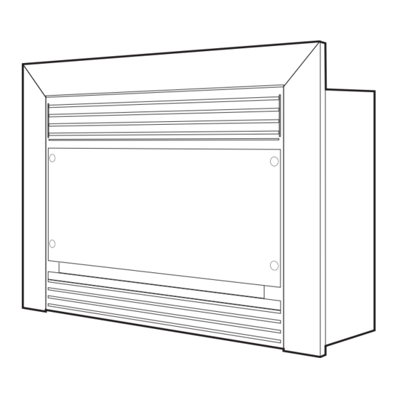
PYROTECH STANDARD
®
INSTALLATION & OPERATING MANUAL
The Pyrotech Space Heater is approved to be installed into a masonry
fireplace or as a zero clearance firebox enclosed by a timber frame &
plastered. The Pyrotech is approved to operate on Natural Gas and
Propane (LPG) gases only. Approval Number 6877.
VERSION 20
Advertisement
Table of Contents

Related Manuals for Real Flame PYROTECH SPACE HEATER


Summary of Contents for Real Flame PYROTECH SPACE HEATER
- Page 1 ® INSTALLATION & OPERATING MANUAL The Pyrotech Space Heater is approved to be installed into a masonry fireplace or as a zero clearance firebox enclosed by a timber frame & plastered. The Pyrotech is approved to operate on Natural Gas and Propane (LPG) gases only.
-
Page 2: Ventilation Requirements
WARRANTY Provided your Real Flame gas fire is installed in strict accordance with our installation instructions, the firebox is unconditionally guaranteed for ten years and all other parts for twelve months from date of purchase. This unconditional warranty covers parts and labour at our discretion taking into consideration normal wear and tear and does not cover fires installed in outdoor settings. -
Page 3: Table Of Contents
Troubleshooting .....................17 Service – Fan ......................18 Service – Igniter .....................19 Service – Burner ....................20 Parts Location/Parts Kit..................21 Gas Control Assembly/Valve Description..............22 Flue Termination Regulations ................23 Optional Marble Surround Installation Procedure ..........25 Optional Mantelpiece Installation Procedure/Dimensions........26 Electrical Diagram....................27 Real Flame Contact Information................28... -
Page 4: Data Plate
DATA PLATE MODEL: PYROTECH SPACE HEATER WEIGHT: 55 kg TYPE INJ/SIZE MJ/H P .T.P . 2 x 1.83mm 0.90 kpa NATURAL GAS 2 x 0.90mm 2.54 kpa PROPANE APPROVAL NUMBER SERIAL NUMBER DATE OF MANUFACTURE 6877... -
Page 5: Inbuilt Model Dimensions/Installation Procedure
PYROTECH INBUILT MODEL • Unit installed into an existing “working” fireplace requires an AGA approved 150mm gas cowl. If the chimney does not draw properly, a 900mm length of flexi flue (supplied with unit) should be fixed to the flue spigot on top of the heater. The flexi flue should be fixed in the vertical position in a manner that does not allow the flue to fall or come away from the spigot. - Page 6 PYROTECH INBUILT MODEL Pyrotech Inbuilt Installation Procedure (continued) Figure (3) Remove nylon grommets and put Figure (4) Remove three spacer bolts, and aside carefully. loosen bolt in bottom right corner. NOTE: Keep coals or pebbles clear of burner rail. Figure (5) Support front glass as shown, and remove fourth spacer bolt.
- Page 7 Pyrotech Inbuilt Installation Procedure (continued) The Pyrotech Space Heater (Natural Gas Only) is approved for use with Pebbles. To install the Pebbles follow the installation instructions as per Figures 1 to 5 above, and then proceed as follows (Figures 10 to 12).
-
Page 8: Zero Clearance Model Timber Frame Installation Procedure
PYROTECH ZERO CLEARANCE MODEL Pyrotech Zero Clearance Timber Frame Installation (Recommended only) (Recommended only) IMPORTANT Install unit and fluing before plasterboard. Plaster to run beyond stud and behind trim HEATER From hearth TRIM Approx 20mm for hearth if required. NOTE: Note: If fire is to be installed off the floor with 4 sided trim, use same A, B, C and D dimensions as shown with frame work included below fire to required height. -
Page 9: Zero Clearance Model
PYROTECH ZERO CLEARANCE MODEL Position the Pyrotech firebox in the selected installation position in the room. You will require the Zero Clearance Kit to suit, which is to be fitted to the main fire box as shown on page 10. ZERO CLEARANCE KIT COMPONENTS No. -
Page 10: Zero Clearance Model Assembly
PYROTECH ZERO CLEARANCE MODEL Fit Zero Clearance Kit to unit as shown below: ITEM 1 ITEM 5 ITEM 2 ITEM 4 ITEM 6 ITEM 3 Secure side strips (Item 1) to side brackets on Place LH side panel (Item 4) in behind lip of fire box using screws (2 off per side strip). -
Page 11: Zero Clearance Model Dimensions/Installation Procedure
PYROTECH ZERO CLEARANCE MODEL Pyrotech Zero Clearance Installation Procedure Connect to gas supply. TICK BOXES Connect to power supply Install flue to 500mm minimum above roof line. (Min total flue run 3.6 m) Plaster to unit with trim removed. Install trim. Assemble unit as per pages 5 - 7. -
Page 12: Freestanding Model Dimensions
PYROTECH FREESTANDING MODEL Cowl 410mm 870mm 735mm Gas Pipe 220mm Ceiling Ring 290mm 4 x 900m Flue Lengths Ceiling Ring 135mm 15mm STANDARD FLUE KIT 750mm 390mm... -
Page 13: Freestanding Model Installation Procedure/Clearances
PYROTECH FREESTANDING MODEL Pyrotech Freestanding Installation Procedure Position unit maintaining correct clearances from combustibles. TICK BOXES Connect to adequate gas supply. Connect to adequate power supply. Install flue kit maintaining minimum 25mm clearances from outer flue to combustibles. Assemble as per pages 5 - 7. Ensure clearances noted below are maintained. -
Page 14: Lighting Procedure
LIGHTING PILOT AND MAIN BURNER The Pyrotech is fitted with a remote operated valve located in the cavity below the burner. The valve is pre wired and completely self contained to generate its own power. Before lighting the pilot make sure that the gas line is connected. DO NOT CONNECT ANY EXTERNAL POWER TO THE VALVE. -
Page 15: Commissioning/Accessing Pilot
TESTS TO BE CARRIED OUT BY INSTALLER • Remove Hi/Lo knob (1). • Connect manometer to hi lo pressure point connection (3.) • Via Hi/Lo knob (1), adjust hi pressure to N.G 0.9 OR LPG 2.54. Do not exceed these settings. •... -
Page 16: Maintenance
ACCESSING PILOT (continued) Figure (3) Remove the small cover plate Figure (4) Remove the two screws holding the pilot assembly to the burner. MAINTENANCE The appliance should be thoroughly inspected before initial use and at least annually by a qualified service technician. If any abnormal condition is observed the home owner must contact a qualified service technician. -
Page 17: Troubleshooting
TROUBLESHOOTING THE MILLIVOLT GAS SYSTEM CONTROL IMPORTANT Valve system troubleshooting should only be carried out by a qualified service technician. If supply cord is damaged or the unit needs repairing, it shall be repaired by the manufacturer or its service agent or similarly qualified person in order to avoid a hazard. Symptom Possible Cause Corrective Action... -
Page 18: Service - Fan
TROUBLESHOOTING FOR FAN OPERATION IMPORTANT The tests below are only to be carried out by an authorised service agent or electrician. Symptom Possible Cause and Corrective Action Fan will not operate Ensure that fire had been operating for at least 20 minutes. Ensure that snap disc is operating. -
Page 19: Service - Igniter
REMOVING FAN (continued) Figure (4) Remove the wing nut on the right hand side of the fan assembly. Figure (5) Slide the fan to the right to remove it from the holding bracket of the left hand side of the fan. Slowly remove the fan turning it slightly to the right. -
Page 20: Service - Burner
REMOVING BURNER When removing the burner, remove the glass as per pages 5 & 6. Remove the pilot from the burner as per page 15. Figure (1) Remove screw from plate at rear of burner and remove plate. Figure (2) Unscrew burner tube at rear of burner and lift burner out. -
Page 21: Parts Location/Parts Kit
PARTS LOCATION 865mm 635mm Pilot Power Generator Valve assembly 95mm Piezo Ignitor PARTS KIT Pilot Thermocouple Piezo Lead Power Generator Piezo Ignitor Valve... -
Page 22: Gas Control Assembly/Valve Description
GAS CONTROL ASSEMBLY PART PART No. AGA Approval SIT 820 NOVA Mv 0820332-NAT GAS 4032 SIT 820 NOVA Mv 0820331-LPG 4032 SIT THERMOCOUPLE 200261 4032 SIT PILOT ASSEMBLY 190610 4032 SIT THERMAL GENERATOR 240002 4032 PIEZO WITH LEAD 28510 4032 PIEZO IGNITOR PUSH BUTTON 73953 4032... -
Page 23: Flue Termination Regulations
PYROTECH FLUE TERMINATION (COWLS) REGULATIONS Natural Draft Refer to Note 1 Refer to Note 1 A OR B 500mm 500mm AREA CLEARANCE REQUIRED Horizontally from a neighboring structure............1000mm If less than a meter horizontally from a neighboring structure then terminates above that structure by............500mm From any opening into a building. - Page 24 THIS PAGE HAS BEEN LEFT BLANK INTENTIONALLY.
-
Page 25: Optional Marble Surround Installation Procedure
OPTIONAL MARBLE HEARTH AND/OR MARGIN SET 1190mm 270mm 620mm 275mm 375mm 1810mm Marble Margin Set Installation Procedure Install Pyrotech without trim. Install marble up to flange on Pyrotech. Use liquid nails to fix to wall. Marble should look like the diagram below once it has been installed and before mantelpiece has been attached. -
Page 26: Optional Mantelpiece Installation Procedure/Dimensions
OPTIONAL MANTELPIECE INSTALLATION MANTELPIECE DIMENSIONS MODEL Universal* 1810 1220 1090 Victorian Arch 1440 1210 Federation Square 1440 1215 * Universal Windsor, Bouvier, Kensington, Freidrich Firebox Plaster Marble Trim Mantel... -
Page 27: Electrical Diagram
ELECTRICAL DIAGRAM Snap Disc 240V Orange Fan Switch Brown White On/Off Switch Blue CONTROL Millivolt System (Not 240V) -
Page 28: Real Flame Contact Information
REAL FLAME PTY LTD ABN 76 006 311 155 Head Office/Factory/Showroom 1340 Ferntree Gully Rd. Scoresby Vic 3179 Ph: (03) 8706 2000 Fax: (03) 8706 2001 E-mail: info@realflame.com.au Richmond - VIC Showroom 300 Swan St. Richmond Vic 3121 Ph: (03) 9428 4443 Fax: (03) 9428 4445 Dandenong - VIC Showroom 9 Lonsdale St.
Need help?
Do you have a question about the PYROTECH SPACE HEATER and is the answer not in the manual?
Questions and answers