Table of Contents

Related Manuals for Real Flame ELEMENT 1800 DOUBLE SIDED


Summary of Contents for Real Flame ELEMENT 1800 DOUBLE SIDED
- Page 1 ELEMENT 1800 DOUBLE SIDED SPACE HEATER INSTALLATION & OPERATING MANUAL The Element 1800 Double Sided space heater is suitable to be installed into a frame out installation. Designed to operate on Natural gas Approval no.GMK 10441 VERSION 3...
-
Page 2: Warranty Information
Date Of Purchase / settlement of property if new home _________________ Model / Serial Number_______________________ This warranty does not cover the cost of claiming under the warranty or transporting the Real Flame Gas Burner to and from the supplier. Our goods come with guarantees that cannot be excluded under the Australian Consumer Law. You are entitled to a replacement or refund for a major failure and for compensation for any other reasonably foreseeable loss or damage. - Page 3 WARNING The Element 1800 Double sided space heater has a primary safety glass fitted. This safety glass is fitted to this appliance to reduce the risk of injury from burns and at no time should this glass be permanently removed.
-
Page 4: Table Of Contents
Commissioning procedure ..................25 Door removal and fitment ..................26 Media Installation....................28 LED lighting option....................36 Operation - User Instructions................38 Wifi device control instructions ................42 Troubleshooting ....................49 Wiring Diagram .....................50 Injector and pilot removal instructions ..............52 Parts List.......................58 Real Flame contact information ................60... -
Page 5: Dataplate
(Affixed to the base of the unit for reference to gas pressure & consumption) DATA PLATE MODEL ELEMENT 1200 INJECTOR SIZE N.G.C. (Mj/hr) GAS TYPE Natural Gas 3 X 2.30 mm 0.88 kPa High / 0.60 kPa Low 39 High/32 Low Max –... -
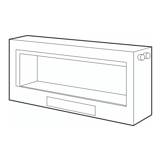
Page 6: Dimensions
DIMENSIONS MINIMUM FRAMEOUT DIMENSIONS (mm) MODEL 1800 DS 2125 Minimum timber frame dimension. Once 10mm plasterboard is added on both sides, this will lead to the frameless trim protruding by approx. 10mm. For a flush finish, C may be increased to 420mm. -
Page 7: Installation Instructions
INSTALLATION INSTRUCTIONS LOCATION Select a location where the fire can be supervised during operation. An electrical isolation switch must be fitted at the appliance or on an adjacent wall to allow for emergency shutdown and maintenance. Installation must meet Australian gas codes AS5601.1-2013 INSTALLATION CLEARANCES –... - Page 8 (continued) INSTALLATION INSTRUCTIONS Flue runs 0m to 5m length (excluding 0-5m rooftop termination) • External wall mount outlet with integrated flue fan (XL model) • External wall mount terminal (Flue fan installed above appliance internally) (XL model) Flue runs 0m to 5m length rooftop termination only •...
-
Page 9: Flue Termination (Cowls)
ELEMENT DS1800 FLUE TERMINATION (COWLS) -
Page 10: Installation Instructions (Continued)
(continued) INSTALLATION INSTRUCTIONS EXTERNAL WALL MOUNTED FAN MODULE INSTALLATION Wall mounted fan module – terminal must be installed with clearances as specified by AS5601.1 Clause 6.9.3 Run exhaust flue and air intake flue as required – Maximum run 3m. Flues can be run next to each other. - Page 11 (continued) INSTALLATION INSTRUCTIONS Apply an 8mm silicon bead fully around the inside of the flue end (heater connection end) Fit flue clamp over flue (loosely). Slide flue onto connection spigot fully. Tighten clamp fully. Wipe excess silicon, visually check connection to ensure connection is fully sealed.
- Page 12 (continued) INSTALLATION INSTRUCTIONS Cut flue exhaust tube (hot tube) to length (Approximately flush with wall exit). Connection plate will sit against wall. Cut Air intake flue. Ensure ends are burr free and round, test fit flue will slide over connection. Pull flue through approx.
- Page 13 (continued) INSTALLATION INSTRUCTIONS Slide flue onto connection spigot fully. Tighten clamp fully. Wipe excess silicon, visually check connection to ensure connection is fully sealed. Feed air intake flue pipe through location spigot and fit retaining screw. Push fan terminal into position. And affix to wall. Uneven or rough surfaces may require sealant along top and side gaps.
- Page 14 (continued) INSTALLATION INSTRUCTIONS Fit front cover.
- Page 15 (continued) INSTALLATION INSTRUCTIONS 0M-5M FLUE – INLINE FAN MODULE WITH WALL TERMINATION Setup with internal fan module with wall termination – mid flue mounted Maximum 5m flue length Wall termination Wall terminal must be installed with clearances as specified by AS5601.1-2013 Clause 6.9.3 Run exhaust flue and air intake flue as required –...
- Page 16 (continued) INSTALLATION INSTRUCTIONS Cut flue to length to suit connection. Ensure ends are burr free and round, test fit flue will fit over connection. Apply an 8mm thick silicon bead fully around heater connection approx. 10mm from the top. Apply an 8mm silicon bead fully around the inside of the flue end (heater connection end) Fit flue clamp over flue (loosely).
- Page 17 (continued) INSTALLATION INSTRUCTIONS Repeat for connection to underside of fan module. Repeat for air intake flue connection. Fan module outlet connection Cut tube to length where required. Ensure ends are burr free and round, test fit flue will slide over connection. Apply an 8mm thick silicon bead fully around heater connection approx.
- Page 18 (continued) INSTALLATION INSTRUCTIONS Slide flue onto connection spigot fully. Tighten clamp fully. Wipe excess silicon, visually check connection to ensure connection is fully sealed. Connect power lead to fan module. Ensure lead is clipped to support where required. Do not use connection to support lead. Connection to wall terminal LOOSE FIT CONNECTIONS (Wall termination connections)
- Page 19 (continued) INSTALLATION INSTRUCTIONS Locate terminal on wall and predrill mounting holes where required. Cut flue exhaust tube (hot tube) to length (Flue must extend a minimum of 50mm past the exit face of wall.) It is recommended that the tubes are cut slightly longer and pushed back into wall upon fixing of wall terminal.
- Page 20 (continued) INSTALLATION INSTRUCTIONS Setup with internal inline fan module with rootop termination – mid flue mounted Maximum 5m flue length Rooftop termination Rooftop termination must be installed with clearances as specified by AS5601.1-2013. Run exhaust flue and air intake flue as required – Maximum total run 5m per flue. Flues can be run next to each other.
- Page 21 (continued) INSTALLATION INSTRUCTIONS Run flue from appliance to bottom entry on fan module. Support flue with brackets as required Cut flue to length to suit connection. Ensure ends are burr free and round, test fit flue will fit over connection. Apply an 8mm thick silicon bead fully around heater connection approx.
- Page 22 (continued) INSTALLATION INSTRUCTIONS Repeat for connection to underside of fan module. Repeat for Air intake flue connection. Fan module outlet connection Cut tube to length where required. Ensure ends are burr free and round, test fit flue will slide over connection. Apply an 8mm thick silicon bead fully around heater connection approx.
- Page 23 (continued) INSTALLATION INSTRUCTIONS Slide flue onto connection spigot fully. Tighten clamp fully. Wipe excess silicon, visually check connection to ensure connection is fully sealed. Connect power lead to fan module. Ensure lead is clipped to support where required. Do not use connection to support lead. Connection to rooftop terminal Prepare roof penetration.
- Page 24 (continued) INSTALLATION INSTRUCTIONS Connect hot exhaust flue and air intake flue as per below. Apply an 8mm silicon bead fully around the inside of the flue end. Fit flue clamp over flue (loosely). Slide flue onto connection spigot fully. Tighten clamp fully. Wipe excess silicon, visually check connection to ensure connection is fully sealed.
-
Page 25: Commissioning Procedure
COMMISSIONING PROCEDURE Once the fire is installed: • Check for gas leaks. • Install media. • Connect the powerflue module loom to fan control unit. • Fit doors. • Carry out the lighting procedure. • Check burner pressures and adjust as per Dataplate. •... -
Page 26: Door Removal And Fitment
DOOR REMOVAL AND FITMENT Door removal (recommended 2 persons) • Remove lower trim. (lift up vertically) • Remove door frame cover (lift up from bottom legs and pull down to remove top from locating tabs.) Note the legs are held in place by magnets and may require gentle prying to remove. - Page 27 (continued) DOOR REMOVAL AND FITMENT • Using 2 people lift door carefully, supporting both the glass and frame. Hold vertically and gently lower down into angle support brackets. • Tilt door back and check all bolt holes line up. Slide door sideways to correct where required. •...
-
Page 28: Media Installation
MEDIA INSTALLATION Driftwood with small ceramic coals • Ensure media retainer is fitted to burner. Burner flame slot should be located centrally. • Spread small coals out over the media support tray, ensure no coals are on the inside of the media retainer area and the burner channel. - Page 29 (continued) MEDIA INSTALLATION Driftwood with glass pebbles • Ensure media retainer is fitted to burner. Burner flame slot should be located centrally. • Spread glass pebbles out over the media support tray, ensure no coals are on the inside of the media retainer area and the burner channel.
- Page 30 (continued) MEDIA INSTALLATION Ceramic pebbles only • Ensure media retainer is fitted to burner. Burner flame slot should be located centrally. • Spread large pebbles over the media support tray, ensure no pebbles are inside the media retainer area and the burner channel. Spread out over area. •...
- Page 31 (continued) MEDIA INSTALLATION Glass pebbles only • Ensure media retainer is fitted to burner. Burner flame slot should be located centrally. • Spread glass pebbles over the media support tray, ensure no pebbles are inside the media retainer area and the burner channel. Spread out over area. •...
- Page 32 (continued) MEDIA INSTALLATION Ceramic pebbles with glass pebbles base • Ensure media retainer is fitted to burner. Burner flame slot should be located centrally. • Spread glass pebbles over the media support tray, ensure no pebbles are inside the media retainer area and the burner channel.
- Page 33 (continued) MEDIA INSTALLATION Forestwood with broken glass • Ensure media retainer is fitted to burner. Burner flame slot should be located centrally. • Spread glass shards over the media support tray, ensure no shards are inside the media retainer area and the burner channel. Spread out over area. •...
- Page 34 (continued) MEDIA INSTALLATION Forestwood with glass pebbles • Ensure media retainer is fitted to burner. Burner flame slot should be located centrally. • Spread glass pebbles over the media support tray, ensure no pebbles are inside the media retainer area and the burner channel. Spread out over area. •...
- Page 35 (continued) MEDIA INSTALLATION Redgum with large ceramic coals • Ensure media retainer is fitted to burner. Burner flame slot should be located centrally. • Spread coals over the media support tray, ensure no coals are inside the media retainer area and the burner channel.
-
Page 36: Led Lighting Option
(continued) MEDIA INSTALLATION Redgum with glass pebbles • Ensure media retainer is fitted to burner. Burner flame slot should be located centrally. • Spread pebbles over the media support tray, ensure no pebbles are inside the media retainer area and the burner channel. Spread out over area. •... - Page 37 4 glass insert panels Locate between pins...
-
Page 38: Operation - User Instructions
OPERATION – USER INSTRUCTIONS • Do not operate if you smell gas. Turn appliance off, extinguish any open flame. Contact your installer or a licensed gasfitter. • Do not use if any part of this appliance has been submerged in water. Contact your installer or a qualified service technician. -
Page 39: Remote Control Operating Guide
• The remote control and the controller are non-serviceable parts and if faulty should be returned to Real Flame Pty Ltd for replacement. Locating the remote The remote houses the thermostat that controls the heat output of the fire. When storing the... - Page 40 (continued) REMOTE CONTROL OPERATING GUIDE Manual mode Manual mode does not require that the time and day of the week are set. Press the or t button to increase or decrease the temperature desired. Automatic mode The automatic mode allows the temperature to be regulated according to a programmed level and time.
- Page 41 (continued) REMOTE CONTROL OPERATING GUIDE Programming • Setting the period starting time The hour and AM/PM settings will now flash. To set the P1 starting time, press and release or t button to increase or decrease the hour setting. Press and hold the or t button for 2 seconds or longer to increase or decrease the hour setting by 1 hour every 0.5 seconds.
-
Page 42: Wifi Device Control Instructions
Note: The programming function is only done via the remote control. Introduction These pages outline the Operation of the Real Flame MKII Thermostat system. The System Includes 1. Real Flame Modulating Valve MKII update 2. Real Flame WiFi Interface MKII 3. - Page 43 (continued) WIFI DEVICE CONTROL INSTRUCTIONS Step by Step – Pushing the Fireplace to a local network Illustration 1: Open up the settings Illustration 2: Select the Access Screen and select the Wi-Fi option point for your Fireplace Illustration 3: Enter the default Illustration 4: Check the password for your Fireplace AP connection status for the Fireplace...
- Page 44 (continued) WIFI DEVICE CONTROL INSTRUCTIONS Step by Step – Pushing the Fireplace to a local network Illustration 5: Open the Fireplace Illustration 6: When prompted, select 'Connect to Network' Illustration 7: Select the Network Illustration 8: The App will start to you want to use search for the device on the network...
- Page 45 (continued) WIFI DEVICE CONTROL INSTRUCTIONS Step by Step – Pushing the Fireplace to a local network Illustration 9: You can now control your Fireplace from the network you are connected to.
- Page 46 (continued) WIFI DEVICE CONTROL INSTRUCTIONS Internet Control If your model supports Internet control, upon using the App after being pushed to a local or home network with internet, the application will prompt you to set up the network features. Set-up Selecting Yes will take you to the Registration requires: sign up screen...
- Page 47 (continued) WIFI DEVICE CONTROL INSTRUCTIONS Step by Step – Pushing the Fireplace to a local network User Added Successfully, your Fireplace is now linked to your account, you can control your Fireplace by logging into the application when prompted Operation When on another network or using your Mobile data, launching the App will present you with the log in screen.
- Page 48 (continued) WIFI DEVICE CONTROL INSTRUCTIONS Pushing the Fireplace to a different home or local network after initial install Pushing the Fireplace to a different home or local network after it has previously been set up, is done at Fireplace power on, when the fireplace is powered off at the Main switch, upon being powered on, the Fireplace will show its Access point (Realflame_XXXXXX) for 30 seconds.
-
Page 49: Troubleshooting
IF YOUR FIREPLACE STILL DOES NOT OPERATE CORRECTLY CONSULT YOUR DEALER. ALL SERVICE AND REPAIRS SHOULD BE PERFORMED BY AN AUTHORISED AGENCY. ALL SPARE PARTS AND OPTIONAL TRIM FINISHES ARE AVAILABLE FROM REAL FLAME PTY LTD. -
Page 50: Wiring Diagram
WIRING DIAGRAM Measuring burner test point pressure The appliance is supplied with a burner pressure test point located under the lower trim on the gas valve side. Remove lower trim to access. -
Page 52: Injector And Pilot Removal Instructions
The media may be carefully lifted out and placed flat to store until refitting. The media can be repainted using an approved high temperature paint, contact Real Flame for details. 14. Turn burner over gently. AVOIDING DAMAGING THE INSULATION. - Page 53 (continued) INJECTOR AND PILOT REMOVAL INSTRUCTIONS 15. Loosen gas pipe nuts form injectors and move gas pipe away. Note – 15mm spanner required for the nuts, a shifter or spanner should be used to support the brass injector assembly. 16. Undo grub screw (Allen key 2.5mm AF). Injector assembly can now be removed.
- Page 54 TAKE CARE – where the burner has been previously used the hard insulation is easily cracked. The insulation media can be repainted using an approved high temperature paint, contact Real Flame for details.
- Page 55 (continued) INJECTOR AND PILOT REMOVAL INSTRUCTIONS Pilot Remove pilot cover screws. Remove pilot bracket holding screw. Gently lift pilot assembly up to enable access to pipe fittings. Remove spark lead Remove spark probe (10mm spanner required) Remove pilot pipe fitting from pilot assembly.
- Page 56 (continued) INJECTOR AND PILOT REMOVAL INSTRUCTIONS Remove pilot orifice from pilot or replace whole pilot assembly with correct gas type. PILOT REFITMENT Replace pilot orifice with correct gas type. Refit pilot gas pipe and tighten. Refit spark probe and gently tightly Refit spark lead Push pilot assembly down to original position and refit the bracket retaining screw.
- Page 57 (continued) INJECTOR AND PILOT REMOVAL INSTRUCTIONS BURNER REFITMENT Carefully place burner into firebox, supporting LH end of the burner. Tighten gas pipe connection to the end of the burner. Burner can now be lowered fully into the firebox. Refit burner retaining screws (2 off). Refit Media support tray.
-
Page 58: Parts List
PARTS LIST Valve SIT Pilot assembly Natural gas Injector Natural gas Millennium receiver Millennium remote control Techrite Ignition pack / gas control... -
Page 60: Real Flame Contact Information
GLEN DIMPLEX AUSTRALIA PTY LTD ABN 69 118 275 460 Head Office/Factory/Showroom 1340 Ferntree Gully Rd. Scoresby Vic 3179 Ph: (03) 8706 2000 Fax: (03) 8706 2001 E-mail: info@realflame.com.au Richmond - VIC Showroom 300 Swan St. Richmond Vic 3121 Ph: (03) 9428 4443 Fax: (03) 9428 4445 Dandenong - VIC Showroom 3/328 South Gippsland Highway, Dandenong South Vic 3164...
Need help?
Do you have a question about the ELEMENT 1800 DOUBLE SIDED and is the answer not in the manual?
Questions and answers