
Related Manuals for Impulse IFP1613


Summary of Contents for Impulse IFP1613
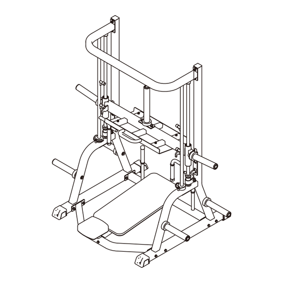
- Page 1 IFP1613 Vertical Leg Press OWNER'S MANUAL CAUTION! Read all precautions and instructions in this manual before using this equipment.
-
Page 2: Table Of Contents
Table Of Contents CAUTION! Read all precautions and instructions in this manual before using this equipment. Important Safety Instructions----------------------------------------------------------- 3 Instructions-------------------------------------------------------------------------------- 5 Exploded View and Parts List------------------------------------------------------------ 6 Measurement Guide--------------------------------------------------------------------- 14 Assembly Instructions------------------------------------------------------------------ 15 Assembly--------------------------------------------------------------------------------- 16 Adjust and Exercise Instruction------------------------------------------------------- 19 Maintenance Schedule------------------------------------------------------------------ 20 General Maintenance Information----------------------------------------------------- 21 Weight Training Tips-------------------------------------------------------------------- 22... -
Page 3: Important Safety Instructions
Important Safety Instructions Before beginning any fitness program, you should obtain a complete physical examination from your physician. When using exercise equipment, basic precautions should always be taken, including the following: 1. Read all instructions before using the equipment. These instructions are written to ensure your safety and to protect the unit. 2. - Page 4 Important Safety Instructions Personal Safety During Assembly Read each step in the assembly instructions and follow the steps in sequence. Do not skip ahead. If you skip ahead, you may learn later that you have to disassemble components and that you may have damaged the equipment. Assemble and operate the equipment on a solid, level surface.
-
Page 5: Instructions
Instructions Before beginning assembly please take the time to read instructions thoroughly. Please use the various lists in this manual to make sure that all parts have been included in your shipment. When ordering, use part number and description from the lists. -
Page 6: Exploded View And Parts List
Exploded View and Parts List Overall Part No. Description Item No. Upright Frame Ⅰ ASSY IFP161301ASSY Upright Frame Ⅱ ASSY IFP161302ASSY IFP161303ASSY Handle Frame ASSY IFP16130400 Front Connecting Frame Sliding Frame ASSY Ⅱ IFP161305ASSY IFP161306ASSY Upper Connection Frame ASSY IFP16130700 Back Pad Support Frame Rotating Frame Ⅰ... - Page 7 Exploded View and Parts List Overall...
- Page 8 Exploded View and Parts List Upright Frame Ⅰ ASSY Upright Frame Ⅱ ASSY Part No. Description Grade No. Upright Frame Ⅰ IFP16130100 Plug □50.8 KPSFID3000 GB17880.5M6*16.5DS17 Rivet Nut M6 IFP12013300 Bottom Foot Plug GB818M6*20DHS2 Cross Recessed Pan Head Screw M6*20 Part No.
- Page 9 Exploded View and Parts List Handle Frame ASSY Sliding Frame ASSY Ⅱ Part No. Description Grade No. IFP16130300 Handle Frame FE97031800 Grip V39500 Aluminum Grip Ring V39600 Aluminum Grip Cap YZGB7710-32*3.2N19 Socket Set Screw 10-32UNF*3.2 Part No. Description Grade No. Sliding Frame ASSY Ⅰ...
- Page 10 Exploded View and Parts List Sliding Frame ASSY Ⅰ Upper Connection Frame ASSY Part No. Description Grade No. 5.1.1 IFP16130500 Sliding Frame 5.1.2 IFP12013400 Weight Horn Sleeve 5.1.3 IFP12013500 Plug Φ49 5.1.4 LM25UU Linear Bearing 5.1.5 HF985A1500 Bumper Φ76*Φ42*25 5.1.6 GB893.140FH12 Circlip for Hole Part No.
- Page 11 Exploded View and Parts List Rotating Frame Ⅰ ASSY Rotating Frame Ⅱ ASSY Part No. Description Grade No. Rotating Frame Ⅰ IFP16130800 FE97031800 Grip V39500 Aluminum Grip Ring V39600 Aluminum Grip Cap BH97213100 Stop Collar BNH0062-1 Bumper YZGB7710-32*3.2N19 Socket Set Screw 10-32UNF*3.2 Part No.
- Page 12 Exploded View and Parts List Long Barbell Frame ASSY Sliding Safety Frame ASSY Ⅰ Part No. Description Grade No. 11.1 IFP16131200 Long Barbell Frame 11.2 IFP12013500 Plug Φ49 11.3 IFP16053000 Weight Horn Sleeve 11.4 HF985A1500 Bumper Φ76*Φ42*25 Part No. Description Grade No.
- Page 13 Exploded View and Parts List Sliding Safety Frame ASSY Ⅱ Barbell Frame ASSY Part No. Description Grade No. 13.1 IFP16131300 Sliding Safety Frame Safety Hook Frame Ⅱ 13.2 IFP16131500 13.3 ES20003400 Nylon Bushing 13.4 CG50001700 Adjustable Back Pad Grip 13.5 M01402000 Barbell Plug Bumper 13.6 GB5780M12*70DHS20 Hex Head Cap Screw M12*70...
-
Page 14: Measurement Guide
Measurement Guide BHCS = Button Head Cap Screw SHCS = Socket Head Cap Screw FHCS = Flat Head Cap Screw HHB = Hex Head Bolt Millimeters Inches Diameter of bolt M6(1/4") M8(5/16") M10(3/8") M12(1/2") M16(5/8") (mm/inch) Tightening 9~12 22~30 45~59 78~104 193~257 torque (N.m) -
Page 15: Assembly Instructions
Assembly Instructions Assembly of the equipment takes professional installers about 2 hours. If this is the first time you have assembled this type of equipment, plan to spend more time. It is strongly recommended to assemble the equipment by professional installers. You may find it quicker, safer, easier to assemble this equipment with the help of a friend, as some of components may be large, heavy or awkward to handle alone. -
Page 16: Assembly
Assembly STEP 1 1. Attach the Handle Frame ASSY (#3) and the Front Connecting Frame (#4) to the Upright Frame Ⅰ ASSY (#1) and the Upright Frame Ⅱ ASSY (#2) using: eight M10*100 HHB (#22) sixteen Φ11*Φ20*2 Flat Washer (#25) eight Nylon Lock Nut M10 (#23) 2. - Page 17 Assembly STEP 2 1. Attach two Guide (#10), one Rotating Frame Ⅰ ASSY (#8) and the Rotating Frame Ⅱ ASSY (#9) to the Upright Frame Ⅰ ASSY (#1) and the Upright Frame Ⅱ ASSY (#2). 2. Attach the Sliding Frame ASSY Ⅱ (#5) to the Guide (#10) Using: two Baffle Ring (#19) two Bumper Φ48*Φ26*15 (#18) one Sliding Safety Frame ASSY Ⅰ(#12)
- Page 18 Assembly STEP 3 1. Attach the Long Barbell Frame ASSY (#11) to the Sliding Frame ASSY Ⅱ (#5) using: two M10*30 HHB (#20) two Φ11*Φ20*2 Flat Washer (#25) two Φ10 Spring Washer (#26) 2. Attach four Barbell Frame ASSY (#14) to the Upright Frame Ⅰ ASSY (#1) and the Upright Frame Ⅱ...
-
Page 19: Adjust And Exercise Instruction
Adjust and Exercise Instruction Sliding Safety Frame Adjustment 1. Pull the Sliding Safety Frame to desired position. 2. Make sure the Sliding Safety Frame gets caught in the hole completely. Weight Plate Installation Requirements 1. Please use Olympic Weight Plate which hole is greater than Φ50mm and external diameter is less than Φ500mm. -
Page 20: Maintenance Schedule
Maintenance Schedule COMMERCIAL HOME LATEST DATE ENTRY ROUTINE MAINTENANCE MAINTENANCE Inspect; Links, Pull Pins, Snap Locks, DAILY WEEKLY Swivels, Weight Stack Pins Clean; DAILY WEEKLY Upholstery Inspect; DAILY WEEKLY Cables or Belts and their tension Inspect; WEEKLY 3 MONTHS Accessory Bars, and Handles Inspect;... -
Page 21: General Maintenance Information
General Maintenance Information Links, Pull-Pins, Snap Hooks, Swivels, Weight Stack Pins: * Check all pieces for signs of visible wear or damage. * Check springs in snap hooks and pull-pins for proper tension and alignment. * If the spring sticks or has lost its rigidity, replace it immediately. Upholstery: * To ensure prolonged upholstery life and proper hygiene, all upholstered pads should be wiped down with a damp cloth after every workout. -
Page 22: Weight Training Tips
Weight Training Tips Use this manual to guide you through the basic exercises you can perform on your equipment. To gain maximum results and avoid possible injury, consult a fitness professional to develop your complete exercise program. Always consult your physician before starting any exercise program. To be successful in your exercise program, it is important to develop an understanding of the basic principles of strength training.
Need help?
Do you have a question about the IFP1613 and is the answer not in the manual?
Questions and answers