
Related Manuals for Impulse IF9315


Summary of Contents for Impulse IF9315
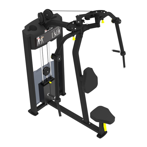
- Page 1 IF9315 PEC FLY/REAR DELT OWNER'S MANUAL 20S Rev B CAUTION! Read all precautions and instructions in this manual before using this equipment.
-
Page 2: Table Of Contents
Table Of Contents CAUTION! Read all precautions and instructions in this manual before using this equipment. Important Safety Instructions----------------------------------------------------------- 3 Instructions-------------------------------------------------------------------------------- 5 Exploded View and Parts List------------------------------------------------------------ 6 Measurement Guide--------------------------------------------------------------------- 16 Assembly Instructions------------------------------------------------------------------ 17 Assembly--------------------------------------------------------------------------------- 18 Adjust Instructions and Exercise Instructions---------------------------------------- 30 Maintenance Schedule------------------------------------------------------------------ 31 General Maintenance Information----------------------------------------------------- 32 Weight Training Tips-------------------------------------------------------------------- 33... -
Page 3: Important Safety Instructions
Important Safety Instructions Before beginning any fitness program, you should obtain a complete physical examination from your physician. When using exercise equipment, basic precautions should always be taken, including the following: 1. Read all instructions before using the equipment. These instructions are written to ensure your safety and to protect the unit. 2. - Page 4 Important Safety Instructions Personal Safety During Assembly Read each step in the assembly instructions and follow the steps in sequence. Do not skip ahead. If you skip ahead, you may learn later that you have to disassemble components and that you may have damaged the equipment. Assemble and operate the equipment on a solid, level surface.
-
Page 5: Instructions
Instructions Before beginning assembly please take the time to read instructions thoroughly. Please use the various lists in this manual to make sure that all parts have been included in your shipment. When ordering, use part number and description from the lists. -
Page 6: Exploded View And Parts List
Exploded View and Parts List Overall Part No. Description ItemNo. Grade No. IF931501ASSY Weight Stack Frame ASSY IF931502ASSY Bottom Cross Frame ASSY IF93150300 Main Frame ASSY IF931504ASSY Top Cross Frame ASSY IF931505ASSY Adjustable Cross Frame ASSY IF931506ASSY Cam 1 ASSY IF931507ASSY Cam 2 ASSY IF931508ASSY... - Page 7 Exploded View and Parts List Overall Part No. Description ItemNo. Grade No. PL90221500 Plug Bumper Φ63.5*Φ15.5*23 IT80011800DS Adjustable Ring M02903100 Pulley SpacerΦ20*Φ10.5*14 FE97211900 Cap Φ60.1*16.1 FE97212000 Circle Ring Φ62.5*5 IF93062200 Big Washer GB818M6*20*20N19 Cross Recessed Pan Head Screw M6*20 GB818M6*10N19 Cross Recessed Pan Head Screw M6*10 GB70M10*20DS20 Socket Head Cap Screw M10*20...
- Page 8 Exploded View and Parts List Full Shroud Overall...
- Page 9 Exploded View and Parts List Half Rear Shroud Overall...
- Page 10 Exploded View and Parts List Weight Stack Frame ASSY Bottom Cross Frame ASSY Grade No. Part No. Description ItemNo. IF9315B0100 Weight Stack Frame BS81223100 Foot Plate GB17880.5M6*16.5DS17 Rivet Nut M6 AC32705800 U-nut M6 Grade No. Part No. Description ItemNo. IF93150200 Bottom Cross Frame IT95120900 Seat Pad Adjustable Frame...
- Page 11 Exploded View and Parts List Top Cross Frame ASSY Adjustable Cross Frame ASSY Grade No. ItemNo. Part No. Description IF93150400 Top Cross Frame Plug □ 25*50 CHL305WS0900 Grade No. Part No. Description ItemNo. IF93150500 Adjustable Cross Frame GB2766205-2ZC3 Deep Groove Ball Bearing Φ25*Φ52*15 IT9315G1500 Position Adjustment Pin...
- Page 12 Exploded View and Parts List Cam 1 ASSY Cam 2 ASSY Grade No. ItemNo. Part No. Description IF93150600 Cam 1 IT95151400 Lining Board 1 GB70M8*20DS20 Socket Head Cap Screw M8*20 GB958DS2 Flat Washer Φ9*Φ16*1.6 NM8DS2 Nylon Lock Nut M8 GB2766205-2ZC3 Deep Groove Ball Bearing Φ25*Φ52*15 IT90054000 Sleeve Φ32*Φ25.4*40...
- Page 13 Exploded View and Parts List Rotary Arm 1 ASSY Rotary Arm 2 ASSY Grade No. Part No. Description ItemNo. IF93150800 Rotary Arm 1 V39600 Aluminum Grip Cap IT90102200 Aluminum Grip Ring IF93153100 Bumper 026-01PL0206-12 Grip STΦ30*Φ22*130 IT95251700 Grip STΦ30*Φ22*240 M02502000 Spacer YZGB7710-32*3.2N19 Socket Set Screw 10-32UNF*3.2...
- Page 14 Exploded View and Parts List Bottom Bracket ASSY Pulley Even Frame ASSY Grade No. Part No. Description ItemNo. 14.1 IF93012200 Bottom Bracket 14.2 GB17880.5M6*16.5DS17 Rivet Nut M6 Grade No. Part No. Description ItemNo. 22.1 IT95271700 Pulley Even Frame 22.2 SG500110400V5 4.5"...
- Page 15 Exploded View and Parts List Front Bracket ASSY Right Bracket ASSY Left Bracket ASSY Grade No. Part No. Des cription ItemNo. 49.1 IF9301B2100 Front Brack et 49.2 ECU7P3500 Plastic Nut Grade No. Part No. Des cription ItemNo. 50.1 IF93SH010100 Right Bracket 50.2 ECU7P3500 Plastic Nut...
-
Page 16: Measurement Guide
Measurement Guide BHCS = Button Head Cap Screw SHCS = Socket Head Cap Screw FHCS = Flat Head Cap Screw HHB = Hex Head Bolt CRPHS = Cross Recessed Pan Head Screw Millimeters Inches Diameter of bolt M6(1/4") M8(5/16") M10(3/8") M12(1/2") M16(5/8") (mm/inch) -
Page 17: Assembly Instructions
Assembly Instructions Assembly of the equipment takes professional installers about 2 hours. If this is the first time you have assembled this type of equipment, plan to spend more time. It is strongly recommended to assemble the equipment by professional installers. You may find it quicker, safer, easier to assemble this equipment with the help of a friend, as some of components may be large, heavy or awkward to handle alone. -
Page 18: Assembly
Assembly STEP 1 Assemble the Weight Stack Frame ASSY (#1), the Bottom Cross Frame ASSY (#2), the Main Frame ASSY (#3), the Top Cross Frame ASSY (#4) and the Bottom Bracket ASSY (#14) together, using: two M10*30 HHB (#42) four M10*75 HHB (#43) three M10*80 HHB (#44) two Φ10 Spring Washer (#45) sixteen Φ11*Φ20*2 Flat Washer (#46) - Page 19 Assembly STEP 2 1. Attach the two 4.5" Pulley (#23), the four (#24) Pulley Cover to the Top Cross Frame ASSY (#4) using: two M10*50 SHCS (#40) two M10 Nylon Lock Nut (#47) 2. Attach the two Adjustable Cross Frame ASSY (#5), the two Adjustable Ring (#32), the Cam 1 ASSY (#6) the Cam 2 ASSY (#7) and the Top Connection Frame (#10) to the Top Cross Frame ASSY (#4) using: three M10*30 HHB (#42)
- Page 20 Assembly Full Shroud Select STEP 1. Attach one Front Bracket ASSY to the Weight Stack Frame ASSY, using: four Plastic Nut four ST4.2*16 Cross Disc Self Tapping Screw 2. Attach one Right Bracket ASSY and one Left Bracket ASSY to the Weight Stack Frame ASSY using: four Plastic Nut four ST4.2*16 Cross Disc Self Tapping Screw...
- Page 21 Assembly STEP 3 Here is the assembly instruction for 160LBS Weights ! 1. Attach: two Guide Rod Φ19*1242 (#21) two Weight Rubber Bumper (#27) fifteen Weight Plate 10LBS (#101) two weight stack space (#103) one Top Plate (#20) to the Weight Stack Frame ASSY (#1) using: two Guide Rod Fixing Sleeve Φ30*Φ19*45 (#29) two Spring (#30) 2.
- Page 22 Assembly STEP 3 Here is the assembly instruction for 200LBS Weights ! 1. Attach: two Guide Rod Φ19*1242 (#21) two Weight Rubber Bumper (#27) nineteen Weight Plate 10LBS (#101) one Top Plate (#20) to the Weight Stack Frame ASSY (#1) using: two Guide Rod Fixing Sleeve Φ30*Φ19*45 (#29) two Spring (#30) 2.
- Page 23 Assembly STEP 3 Here is the assembly instruction for 235LBS Weights ! 1. Attach: two Guide Rod Φ19*1242 (#21) two Weight Rubber Bumper (#27) fifteen Weight Plate 15LBS (#102) two weight stack space (#103) one Top Plate (#20) to the Weight Stack Frame ASSY (#1) using: two Guide Rod Fixing Sleeve Φ30*Φ19*45 (#29) two Spring (#30) 2.
- Page 24 Assembly STEP 3 Here is the assembly instruction for 295LBS Weights ! 1. Attach: two Guide Rod Φ19*1242 (#21) two Weight Rubber Bumper (#27) nineteen Weight Plate 15LBS (#102) one Top Plate (#20) to the Weight Stack Frame ASSY (#1) using: two Guide Rod Fixing Sleeve Φ30*Φ19*45 (#29) two Spring (#30) 2.
- Page 25 Assembly All weight plate sticker paste schematic diagram...
- Page 26 Assembly STEP 4 1. Attach the Cable (#12) to the Pulley Even Frame ASSY (#22), the Cam 1 ASSY (#6) and the Cam 2 ASSY (#7). 2. Attach the two CRPHS M4*16 (#48) to the Cam 1 ASSY (#6) and the Cam 2 ASSY (#7).
- Page 27 Assembly Full Shroud STEP 5 1. Attach the two Top Bracket (#13) to the Training Placard Cover (#17) and the Top Rear Shroud (#19) using: four M6*10 CRPHS (#38) 2. Attach the two Notched Front Shroud (#52) and the Training Placard Cover (#17) to the Weight Stack Frame ASSY (#1) using: six M6*20 CRPHS (#37) four ST4.2*16 Cross Disc Self Tapping Screw (#54)
- Page 28 Assembly Half Rear Shroud STEP 5 1. Attach the two Top Bracket (#13) to the Weight Stack Frame ASSY (#1) using: four M6*20 CRPHS(#37) 2. Attach the Half Rear Shroud (#55) to the Weight Stack Frame ASSY (#1) using: six M6*20 CRPHS(#37) 3.
- Page 29 Assembly STEP 6 1. Attach the Top Cover (#18) to the Weight Stack Frame ASSY (#1) using: two M6*20 CRPHS (#37) 2. Attach the Right Plug (#15) and the Left Plug (#16) to the Weight Stack Frame ASSY (#1). 3. Attach the two Seat Pad (#25) to the Bottom Cross Frame ASSY (#2) and the Main Frame ASSY (#3) respectively, using: four M10*30 HHB (#42) four Φ11*Φ20*2 Flat Washer (#46)
-
Page 30: Adjust Instructions And Exercise Instructions
Adjust Instructions and Exercise Instructions The Seat Pad adjustment 1. Push the Adjustable Support and adjust the Seat Pad to the desired position. 2. Make sure the pin gets into the hole completely. The Use Position adjustment 1. Pull the Adjustable Support and adjust the two Adjustable Cross Frame ASSY to the desired position. -
Page 31: Maintenance Schedule
Maintenance Schedule COMMERCIAL HOME LATEST DATE ENTRY ROUTINE MAINTENANCE MAINTENANCE Inspect; Links, Pull Pins, Snap Locks, DAILY WEEKLY Swivels, Weight Stack Pins Clean; DAILY WEEKLY Upholstery Inspect; DAILY WEEKLY Cables or Belts and their tension Inspect; WEEKLY 3 MONTHS Accessory Bars, and Handles Inspect;... -
Page 32: General Maintenance Information
General Maintenance Information Links, Pull-Pins, Snap Hooks, Swivels, Weight Stack Pins: * Check all pieces for signs of visible wear or damage. * Check springs in snap hooks and pull-pins for proper tension and alignment. * If the spring sticks or has lost its rigidity, replace it immediately. Upholstery: * To ensure prolonged upholstery life and proper hygiene, all upholstered pads should be wiped down with a damp cloth after every workout. -
Page 33: Weight Training Tips
Weight Training Tips Use this manual to guide you through the basic exercises you can perform on your equipment. To gain maximum results and avoid possible injury, consult a fitness professional to develop your complete exercise program. Always consult your physician before starting any exercise program. To be successful in your exercise program, it is important to develop an understanding of the basic principles of strength training.
Need help?
Do you have a question about the IF9315 and is the answer not in the manual?
Questions and answers