ZyXEL Communications ZYWALL 35 User Manual
Internet security appliance
Hide thumbs
Also See for ZYWALL 35:
- User manual (832 pages) ,
- Support notes (335 pages) ,
- Quick start manual (142 pages)

Related Manuals for ZyXEL Communications ZYWALL 35


Summary of Contents for ZyXEL Communications ZYWALL 35
- Page 1 ZyWALL 5/35/70 Series Internet Security Appliance User’s Guide Version 4.03 1/2008 Edition 1 DEFAULT LOGIN IP Address http://192.168.1.1 Password 1234 www.zyxel.com...
-
Page 3: About This User's Guide
• Supporting Disk Refer to the included CD for support documents. • ZyXEL Web Site Please refer to www.zyxel.com for additional support documentation and product certifications. User Guide Feedback Help us help you. Send all User Guide-related comments, questions or suggestions for improvement to the following address, or use e-mail instead. -
Page 4: Document Conventions
Document Conventions Document Conventions Warnings and Notes These are how warnings and notes are shown in this User’s Guide. Warnings tell you about things that could harm you or your device. Notes tell you other important information (for example, other things you may need to configure or helpful tips) or recommendations. - Page 5 Document Conventions Icons Used in Figures Figures in this User’s Guide may use the following generic icons. The ZyWALL icon is not an exact representation of your device. ZyWALL Computer Notebook computer Server Firewall Telephone Switch Router ZyWALL 5/35/70 Series User’s Guide...
-
Page 6: Safety Warnings
Safety Warnings Safety Warnings For your safety, be sure to read and follow all warning notices and instructions. • Do NOT use this product near water, for example, in a wet basement or near a swimming pool. • Do NOT expose your device to dampness, dust or corrosive liquids. •... - Page 7 Safety Warnings This product is recyclable. Dispose of it properly. ZyWALL 5/35/70 Series User’s Guide...
- Page 8 Safety Warnings ZyWALL 5/35/70 Series User’s Guide...
-
Page 9: Table Of Contents
Contents Overview Contents Overview Introduction ..........................53 Getting to Know Your ZyWALL ....................55 Introducing the Web Configurator ....................61 Wizard Setup ..........................87 Tutorials ........................... 109 Registration ..........................141 Network ..........................147 LAN Screens ........................... 149 Bridge Screens ........................161 WAN Screens .......................... - Page 10 Contents Overview Reports, Logs and Maintenance ..................533 Reports ............................ 535 Logs Screens ........................... 547 Maintenance ..........................575 SMT and Troubleshooting ....................593 Introducing the SMT ........................ 595 SMT Menu 1 - General Setup ....................603 WAN and Dial Backup Setup ....................609 LAN Setup ..........................
-
Page 11: Table Of Contents
Table of Contents Table of Contents About This User's Guide ......................3 Document Conventions......................4 Safety Warnings........................6 Contents Overview ........................9 Table of Contents........................11 List of Figures ......................... 31 List of Tables........................... 45 Part I: Introduction................. 53 Chapter 1 Getting to Know Your ZyWALL.................... - Page 12 Table of Contents 2.4.4 HOME Screen: Bridge Mode ..................71 2.4.5 Navigation Panel ......................74 2.4.6 Port Statistics ......................80 2.4.7 Show Statistics: Line Chart ..................81 2.4.8 DHCP Table Screen ....................82 2.4.9 VPN Status ......................... 83 2.4.10 Bandwidth Monitor ....................84 Chapter 3 Wizard Setup ...........................
- Page 13 Table of Contents 4.4.1 Inserting a 3G Card ....................130 4.4.2 Configuring 3G WAN Settings .................. 131 4.4.3 Checking WAN Connections ..................132 4.5 Configuring Load Balancing ....................132 4.6 Configuring Content Filtering ..................... 133 4.6.1 Enable Content Filtering ................... 133 4.6.2 Block Categories of Web Content ................
- Page 14 Table of Contents 7.2.2 STP Terminology ...................... 162 7.2.3 How STP Works ....................... 162 7.2.4 STP Port States ......................163 7.3 Bridge ..........................163 7.4 Bridge Port Roles ......................165 Chapter 8 WAN Screens......................... 167 8.1 WAN Overview ........................167 8.2 Multiple WAN ........................
- Page 15 Table of Contents 9.3 DMZ Static DHCP ......................206 9.4 DMZ IP Alias ........................207 9.5 DMZ Public IP Address Example ..................209 9.6 DMZ Private and Public IP Address Example ..............209 9.7 DMZ Port Roles ....................... 210 Chapter 10 WLAN .............................
- Page 16 Table of Contents Part III: Security..................241 Chapter 11 Firewall........................... 243 11.1 Firewall Overview ......................243 11.2 Packet Direction Matrix ....................244 11.3 Packet Direction Examples ....................246 11.3.1 To VPN Packet Direction ..................247 11.3.2 From VPN Packet Direction ................... 248 11.3.3 From VPN To VPN Packet Direction ..............
- Page 17 Table of Contents 13.3.2 Intrusion Severity ....................283 13.3.3 Signature Actions ....................283 13.3.4 Configuring IDP Signatures ..................284 13.3.5 Query View ......................286 13.4 Update ..........................290 13.4.1 mySecurityZone ..................... 290 13.4.2 Configuring IDP Update ..................291 13.5 Backup and Restore ......................293 Chapter 14 Anti-Virus..........................
- Page 18 Table of Contents 16.1 Content Filtering Overview ....................321 16.1.1 Restrict Web Features ................... 321 16.1.2 Create a Filter List ....................321 16.1.3 Customize Web Site Access ................. 321 16.2 Content Filtering with an External Database ..............321 16.3 Content Filter General Screen ..................322 16.4 Content Filter Policy .....................
- Page 19 Table of Contents 18.10.2 Authentication and the Security Parameter Index (SPI) ........380 18.11 VPN Rules (Manual) ...................... 380 18.12 VPN Rules (Manual): Edit ................... 382 18.13 VPN SA Monitor ......................385 18.14 VPN Global Setting ....................... 385 18.14.1 Local and Remote IP Address Conflict Resolution ..........385 18.15 Telecommuter VPN/IPSec Examples ................
- Page 20 Table of Contents 20.1.2 RADIUS ........................425 20.2 Local User Database ..................... 425 20.3 RADIUS ......................... 427 Part IV: Advanced ................429 Chapter 21 Network Address Translation (NAT)..................431 21.1 NAT Overview ........................ 431 21.1.1 NAT Definitions ...................... 431 21.1.2 What NAT Does ..................... 432 21.1.3 How NAT Works .....................
- Page 21 Table of Contents 23.5 Policy Route Edit ......................455 Chapter 24 Bandwidth Management....................... 459 24.1 Bandwidth Management Overview ................. 459 24.2 Bandwidth Classes and Filters ..................459 24.3 Proportional Bandwidth Allocation ................... 460 24.4 Application-based Bandwidth Management ..............460 24.5 Subnet-based Bandwidth Management ................460 24.6 Application and Subnet-based Bandwidth Management ..........
- Page 22 Table of Contents 25.10.2 High Availability ....................484 25.11 Configuring Dynamic DNS ..................... 484 Chapter 26 Remote Management......................487 26.1 Remote Management Overview ..................487 26.1.1 Remote Management Limitations ................488 26.1.2 System Timeout ..................... 488 26.2 WWW (HTTP and HTTPS) .................... 488 26.3 WWW ..........................
- Page 23 Table of Contents 27.1.3 Cautions with UPnP ....................515 27.1.4 UPnP and ZyXEL ....................516 27.2 Configuring UPnP ......................516 27.3 Displaying UPnP Port Mapping ..................517 27.4 Installing UPnP in Windows Example ................518 27.4.1 Installing UPnP in Windows Me ................519 27.4.2 Installing UPnP in Windows XP ................
- Page 24 Table of Contents 30.2.3 Viewing Protocol/Port ..................... 539 30.2.4 System Reports Specifications ................540 30.3 IDP Threat Reports Screen ................... 540 30.4 Anti-Virus Threat Reports Screen ................. 542 30.5 Anti-Spam Threat Reports Screen .................. 544 Chapter 31 Logs Screens ........................547 31.1 Configuring View Log ......................
- Page 25 Table of Contents 33.1 Introduction to the SMT ....................595 33.2 Accessing the SMT via the Console Port ................ 595 33.2.1 Initial Screen ......................595 33.2.2 Entering the Password ................... 596 33.3 Navigating the SMT Interface ..................596 33.3.1 Main Menu ......................597 33.3.2 SMT Menus Overview ....................
- Page 26 Table of Contents 37.4 Configuring the PPPoE Client ..................632 37.5 Basic Setup Complete ..................... 633 Chapter 38 DMZ Setup ..........................635 38.1 Configuring DMZ Setup ....................635 38.2 DMZ Port Filter Setup ...................... 635 38.3 TCP/IP Setup ........................636 38.3.1 IP Address ......................
- Page 27 Table of Contents 43.1 Using NAT ........................663 43.1.1 SUA (Single User Account) Versus NAT ..............663 43.1.2 Applying NAT ......................663 43.2 NAT Setup ........................665 43.2.1 Address Mapping Sets ................... 666 43.3 Configuring a Server behind NAT ..................671 43.4 General NAT Examples ....................
- Page 28 Table of Contents 47.1 Introduction to System Status ..................703 47.2 System Status ........................703 47.3 System Information and Console Port Speed ..............705 47.3.1 System Information ....................705 47.3.2 Console Port Speed ....................706 47.4 Log and Trace ........................707 47.4.1 Viewing Error Log ....................
- Page 29 Table of Contents Chapter 49 System Maintenance Menus 8 to 10..................729 49.1 Command Interpreter Mode .................... 729 49.2 Call Control Support ......................730 49.2.1 Budget Management ....................730 49.2.2 Call History ......................731 49.3 Time and Date Setting ..................... 732 Chapter 50 Remote Management......................
- Page 30 Table of Contents Appendix B Pop-up Windows, JavaScripts and Java Permissions ........771 Appendix C Removing and Installing a Fuse ..............779 Appendix D Setting up Your Computer’s IP Address ............781 Appendix E IP Addresses and Subnetting ................803 Appendix F Common Services.....................
-
Page 31: List Of Figures
Figure 2 VPN Application ........................57 Figure 3 3G WAN Application ......................... 58 Figure 4 ZyWALL 70 Front Panel ......................58 Figure 5 ZyWALL 35 Front Panel ......................58 Figure 6 ZyWALL 5 Front Panel ......................58 Figure 7 Change Password Screen ......................62 Figure 8 Replace Certificate Screen ....................... - Page 32 List of Figures Figure 39 Anti-Spam Wizard: Setup Complete ..................108 Figure 40 Dynamic VPN Rule Example ....................109 Figure 41 VPN Gateway Policy Edit Screens ..................112 Figure 42 SECURITY > VPN > Add Network Policy (ZyWALL A) ............113 Figure 43 VPN Network Policy Edit Screens ..................114 Figure 44 Activate VPN Rule (ZyWALL B) ...................115 Figure 45 Tutorial: VPN Summary Screens Comparison Example ............116 Figure 46 Check The Telecommuter's Computer IP Address ...............117...
- Page 33 List of Figures Figure 82 NETWORK > LAN > IP Alias ....................157 Figure 83 NETWORK > LAN > Port Roles ................... 159 Figure 84 Port Roles Change Complete ....................159 Figure 85 Bridge Loop: Bridge Connected to Wired LAN ..............161 Figure 86 NETWORK >...
- Page 34 List of Figures Figure 125 WIRELESS > Wi-Fi > Wireless Card: WPA ................ 233 Figure 126 WIRELESS > Wi-Fi > Wireless Card: 802.1x + Dynamic WEP .......... 234 Figure 127 WIRELESS > Wi-Fi > Wireless Card: 802.1x + Static WEP ..........235 Figure 128 WIRELESS >...
- Page 35 List of Figures Figure 168 SECURITY > IDP > Update ....................291 Figure 169 SECURITY > IDP > Backup & Restore ................293 Figure 170 ZyWALL Anti-virus Example .................... 297 Figure 171 SECURITY > ANTI-VIRUS > General ................299 Figure 172 SECURITY > ANTI-VIRUS > Signature: Query View ............301 Figure 173 Query Example Search Criteria ..................
- Page 36 List of Figures Figure 211 Virtual Mapping of Local and Remote Network IP Addresses ..........370 Figure 212 VPN: Transport and Tunnel Mode Encapsulation .............. 371 Figure 213 SECURITY > VPN > VPN Rules (IKE) > Edit Network Policy ........... 373 Figure 214 SECURITY >...
- Page 37 List of Figures Figure 254 Port Translation Example ....................443 Figure 255 ADVANCED > NAT > Port Forwarding ................444 Figure 256 Trigger Port Forwarding Process: Example ................ 445 Figure 257 ADVANCED > NAT > Port Triggering ................. 446 Figure 258 Example of Static Routing Topology ................... 449 Figure 259 ADVANCED >...
- Page 38 List of Figures Figure 297 SSH Communication Over the WAN Example ..............501 Figure 298 How SSH Works ......................... 501 Figure 299 ADVANCED > REMOTE MGMT > SSH ................503 Figure 300 SSH Example 1: Store Host Key ..................504 Figure 301 SSH Example 2: Test ......................
- Page 39 List of Figures Figure 340 Synchronization Fail ......................581 Figure 341 MAINTENANCE > Device Mode (Router Mode) ..............583 Figure 342 MAINTENANCE > Device Mode (Bridge Mode) ..............584 Figure 343 MAINTENANCE > Firmware Upload .................. 585 Figure 344 Firmware Upload In Process ....................586 Figure 345 Network Temporarily Disconnected ..................
- Page 40 List of Figures Figure 383 Menu 5: DMZ Setup ......................636 Figure 384 Menu 5.2: TCP/IP and DHCP Ethernet Setup ..............636 Figure 385 Menu 5.2.1: IP Alias Setup ....................637 Figure 386 Menu 6: Route Setup ......................639 Figure 387 Menu 6.1: Route Assessment .................... 639 Figure 388 Menu 6.2: Traffic Redirect ....................
- Page 41 List of Figures Figure 426 Example 4: Menu 15.1.1.1: Address Mapping Rule ............679 Figure 427 Example 4: Menu 15.1.1: Address Mapping Rules ............680 Figure 428 Menu 15.3.1: Trigger Port Setup ..................681 Figure 429 Menu 21: Filter and Firewall Setup ..................683 Figure 430 Menu 21.2: Firewall Setup ....................
- Page 42 List of Figures Figure 469 Telnet Into Menu 24.7.1: Upload System Firmware ............724 Figure 470 Telnet Into Menu 24.7.2: System Maintenance ..............724 Figure 471 FTP Session Example of Firmware File Upload ..............725 Figure 472 Menu 24.7.1 As Seen Using the Console Port ..............727 Figure 473 Example Xmodem Upload ....................
- Page 43 List of Figures Figure 512 Windows XP: Control Panel ....................785 Figure 513 Windows XP: Control Panel: Network Connections: Properties ......... 786 Figure 514 Windows XP: Local Area Connection Properties ............... 786 Figure 515 Windows XP: Internet Protocol (TCP/IP) Properties ............787 Figure 516 Windows XP: Advanced TCP/IP Properties ...............
- Page 44 List of Figures Figure 555 Windows 98 SE: StartUp ....................833 Figure 556 Windows 98 SE: Startup: Create Shortcut ..............833 Figure 557 Windows 98 SE: Startup: Select a Title for the Program ..........834 Figure 558 Windows 98 SE: Startup: Shortcut ................... 834 Figure 559 VPN Rules ..........................
-
Page 45: List Of Tables
List of Tables List of Tables Table 1 ZyWALL Model Specific Features ..................... 56 Table 2 Front Panel Lights ........................59 Table 3 Title Bar: Web Configurator Icons ..................... 64 Table 4 Web Configurator HOME Screen in Router Mode ..............65 Table 5 Web Configurator HOME Screen in Bridge Mode .............. - Page 46 List of Tables Table 39 Load Balancing: Spillover ...................... 178 Table 40 Private IP Address Ranges ....................179 Table 41 NETWORK > WAN > WAN (Ethernet Encapsulation) ............181 Table 42 NETWORK > WAN > WAN (PPPoE Encapsulation) ............184 Table 43 NETWORK >...
- Page 47 List of Tables Table 82 SECURITY > IDP > Signature: Query View ................286 Table 83 SECURITY > IDP > Update ....................292 Table 84 Common Computer Virus Types ................... 295 Table 85 SECURITY > ANTI-VIRUS > General .................. 299 Table 86 SECURITY >...
- Page 48 List of Tables Table 125 SECURITY > CERTIFICATES > Directory Server > Add ........... 423 Table 126 SECURITY > AUTH SERVER > Local User Database ............427 Table 127 SECURITY > AUTH SERVER > RADIUS ................427 Table 128 NAT Definitions ........................431 Table 129 NAT Mapping Types ......................
- Page 49 List of Tables Table 168 REPORTS > THREAT REPORTS > Anti-Virus ..............543 Table 169 REPORTS > THREAT REPORTS > Anti-Spam ..............544 Table 170 LOGS > View Log ....................... 548 Table 171 Log Description Example ....................548 Table 172 LOGS > Log Settings ......................552 Table 173 System Maintenance Logs ....................
- Page 50 List of Tables Table 211 Menu 1: General Setup (Bridge Mode) ................604 Table 212 Menu 1.1: Configure Dynamic DNS ..................605 Table 213 Menu 1.1.1: DDNS Host Summary ..................606 Table 214 Menu 1.1.1: DDNS Edit Host ....................607 Table 215 MAC Address Cloning in WAN Setup .................
- Page 51 Table 269 Firmware Specifications ...................... 758 Table 270 Feature and Performance Specifications ................759 Table 271 Compatible ZyXEL WLAN Cards and Security Features ............ 760 Table 272 3G Features Supported By Compatible 3G Cards .............. 761 Table 273 North American Plug Standards ..................762 Table 274 European Plug Standards ....................
- Page 52 List of Tables ZyWALL 5/35/70 Series User’s Guide...
-
Page 53: Introduction
Introduction Getting to Know Your ZyWALL (55) Introducing the Web Configurator (61) Wizard Setup (87) Tutorials (109) Registration (141) -
Page 55: Getting To Know Your Zywall
The ZyWALL is designed for small and medium sized business that need the increased throughput and reliability of dual WAN interfaces and load balancing. The ZyWALL 35 and ZyWALL 5 provide the option to change port roles from LAN to DMZ. -
Page 56: Ways To Manage The Zywall
Chapter 1 Getting to Know Your ZyWALL Chapter 54 on page 757 for a complete list of features. Table 1 ZyWALL Model Specific Features MODEL # FEATURE Two WAN Ports 3G Card Supported Load Balancing Changing Port Roles between LAN and DMZ Changing Port Roles between LAN and WLAN Table Key: A Y in a model’s column shows that the model has the specified feature. -
Page 57: Applications For The Zywall
Chapter 1 Getting to Know Your ZyWALL • Back up the configuration (and make sure you know how to restore it). Restoring an earlier working configuration may be useful if the device becomes unstable or even crashes. If you forget your password, you will have to reset the ZyWALL to its factory default settings. -
Page 58: Wan Application (Zywall 5 Only)
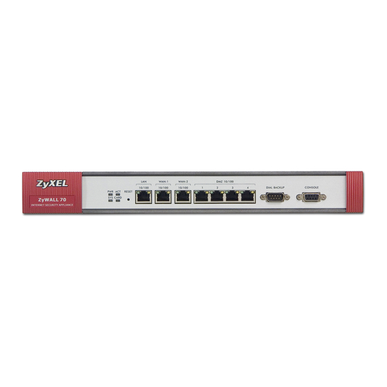
WAN connections as a backup. Figure 3 3G WAN Application 1.5.4 Front Panel Lights Figure 4 ZyWALL 70 Front Panel Figure 5 ZyWALL 35 Front Panel Figure 6 ZyWALL 5 Front Panel ZyWALL 5/35/70 Series User’s Guide... -
Page 59: Table 2 Front Panel Lights
The 100M LAN is sending or receiving packets. LAN/DMZ 10/ The LAN/DMZ is not connected. Green The ZyWALL has a successful 10Mbps Ethernet connection. (ZyWALL 35 and ZyWALL 5) Flashing The 10M LAN is sending or receiving packets. Orange The ZyWALL has a successful 100Mbps Ethernet connection. - Page 60 Chapter 1 Getting to Know Your ZyWALL ZyWALL 5/35/70 Series User’s Guide...
-
Page 61: Introducing The Web Configurator
H A P T E R Introducing the Web Configurator This chapter describes how to access the ZyWALL web configurator and provides an overview of its screens. 2.1 Web Configurator Overview The web configurator is an HTML-based management interface that allows easy ZyWALL setup and management via Internet browser. -
Page 62: Figure 7 Change Password Screen
Chapter 2 Introducing the Web Configurator 5 You should see a screen asking you to change your password (highly recommended) as shown next. Type a new password (and retype it to confirm) and click Apply or click Ignore. Figure 7 Change Password Screen 6 Click Apply in the Replace Certificate screen to create a certificate using your ZyWALL’s MAC address that will be specific to this device. -
Page 63: Resetting The Zywall
5 Release the RESET button and wait for the ZyWALL to finish restarting. 2.3.2 Uploading a Configuration File Via Console Port 1 Download the default configuration file from the ZyXEL FTP site, unzip it and save it in a folder. -
Page 64: Navigating The Zywall Web Configurator
Chapter 2 Introducing the Web Configurator 2.4 Navigating the ZyWALL Web Configurator The following summarizes how to navigate the web configurator from the HOME screen. This guide uses the ZyWALL 70 screenshots as an example. The screens may vary slightly for different ZyWALL models. -
Page 65: Main Window
Chapter 2 Introducing the Web Configurator 2.4.2 Main Window The main window shows the screen you select in the navigation panel. It is discussed in more detail in the rest of this document. Right after you log in, the HOME screen is displayed. The screen varies according to the device mode you select in the MAINTENANCE >... - Page 66 The first number shows how many megabytes of the heap memory the ZyWALL is using. Heap memory refers to the memory that is not used by ZyNOS (ZyXEL Network Operating System) and is thus available for running processes like NAT, VPN and the firewall.
- Page 67 Chapter 2 Introducing the Web Configurator Table 4 Web Configurator HOME Screen in Router Mode (continued) LABEL DESCRIPTION Status For the LAN, DMZ and WLAN ports, this displays the port speed and duplex setting. Ethernet port connections can be in half-duplex or full-duplex mode. Full- duplex refers to a device's ability to send and receive simultaneously, while half- duplex indicates that traffic can flow in only one direction at a time.
- Page 68 Chapter 2 Introducing the Web Configurator Table 4 Web Configurator HOME Screen in Router Mode (continued) LABEL DESCRIPTION Virus Detected This displays how many virus-infected files the ZyWALL has detected since it last started up. It also displays the percentage of virus-infected files out of the total number of files that the ZyWALL has scanned (since it last started up).
- Page 69 Chapter 2 Introducing the Web Configurator Table 4 Web Configurator HOME Screen in Router Mode (continued) LABEL DESCRIPTION Last Connection This displays how long the 3G connection has been up. Up Time Tx Bytes This displays the total number of data frames transmitted. Rx Bytes This displays the total number of data frames received.
- Page 70 Chapter 2 Introducing the Web Configurator Table 4 Web Configurator HOME Screen in Router Mode (continued) LABEL DESCRIPTION Disable budget This field displays if you have enabled budget control but insert a 3G card with a control different user account from the one for which you configured budget control. Select this option to disable budget control.
-
Page 71: Home Screen: Bridge Mode
Chapter 2 Introducing the Web Configurator 2.4.4 HOME Screen: Bridge Mode The following screen displays when the ZyWALL is set to bridge mode. In bridge mode, the ZyWALL functions as a transparent firewall (also known as a bridge firewall). The ZyWALL bridges traffic traveling between the ZyWALL's interfaces and still filters and inspects packets. - Page 72 The first number shows how many megabytes of the heap memory the ZyWALL is using. Heap memory refers to the memory that is not used by ZyNOS (ZyXEL Network Operating System) and is thus available for running processes like NAT, VPN and the firewall.
- Page 73 Chapter 2 Introducing the Web Configurator Table 5 Web Configurator HOME Screen in Bridge Mode (continued) LABEL DESCRIPTION Bridge Hello This is the interval of BPDUs (Bridge Protocol Data Units) from the root bridge. Time Bridge Max Age This is the predefined interval that a bridge waits to get a Hello message (BPDU) from the root bridge.
-
Page 74: Navigation Panel
Chapter 2 Introducing the Web Configurator Table 5 Web Configurator HOME Screen in Bridge Mode (continued) LABEL DESCRIPTION Spam Mail This displays how many spam e-mails the ZyWALL has detected since it last Detected started up. It also displays the percentage of spam e-mail out of the total number of e-mails that the ZyWALL has scanned (since it last started up). -
Page 75: Table 7 Screens Summary
Chapter 2 Introducing the Web Configurator Table 6 Bridge and Router Mode Features Comparison FEATURE BRIDGE MODE ROUTER MODE Bridge WLAN Wireless Card Firewall Anti-Virus Anti-Spam Content Filter Certificates Authentication Server Static Route Policy Route Bandwidth Management Remote Management UPnP Custom Application Reports Logs... - Page 76 Port Roles Use this screen to change the DMZ/WLAN port roles on the ZyWALL 70 or the LAN/DMZ/WLAN port roles on the ZyWALL 5 or ZyWALL 35. General This screen allows you to configure load balancing, route priority and traffic redirect properties.
- Page 77 Chapter 2 Introducing the Web Configurator Table 7 Screens Summary (continued) LINK FUNCTION FIREWALL Default Rule Use this screen to activate/deactivate the firewall and the direction of network traffic to which to apply the rule Rule Summary This screen shows a summary of the firewall rules, and allows you to edit/add a firewall rule.
- Page 78 Chapter 2 Introducing the Web Configurator Table 7 Screens Summary (continued) LINK FUNCTION CERTIFICATES My Certificates Use this screen to view a summary list of certificates and manage certificates and certification requests. Trusted CAs Use this screen to view and manage the list of the trusted CAs. Trusted Use this screen to view and manage the certificates belonging to Remote Hosts...
- Page 79 Chapter 2 Introducing the Web Configurator Table 7 Screens Summary (continued) LINK FUNCTION REMOTE Use this screen to configure through which interface(s) and from MGMT which IP address(es) users can use HTTPS or HTTP to manage the ZyWALL. Use this screen to configure through which interface(s) and from which IP address(es) users can use Secure Shell to manage the ZyWALL.
-
Page 80: Port Statistics
Chapter 2 Introducing the Web Configurator Table 7 Screens Summary (continued) LINK FUNCTION MAINTENANCE General This screen contains administrative. Password Use this screen to change your password. Time and Date Use this screen to change your ZyWALL’s time and date. Device Mode Use this screen to configure and have your ZyWALL work as a router or a bridge. -
Page 81: Show Statistics: Line Chart
Chapter 2 Introducing the Web Configurator Table 8 HOME > Port Statistics (continued) LABEL DESCRIPTION Status For the WAN interface(s) and the Dial Backup port, this displays the port speed and duplex setting if you’re using Ethernet encapsulation or the remote node name for a PPP connection and Down (line is down or not connected), Idle (line (ppp) idle), Dial (starting to trigger a call) or Drop (dropping a call) if you’re using PPPoE encapsulation. -
Page 82: Dhcp Table Screen
Chapter 2 Introducing the Web Configurator The following table describes the labels in this screen. Table 9 HOME > Show Statistics > Line Chart LABEL DESCRIPTION Click the icon to go back to the Show Statistics screen. Port Select the check box(es) to display the throughput statistics of the corresponding interface(s). -
Page 83: Vpn Status
Chapter 2 Introducing the Web Configurator Table 10 HOME > Show DHCP Table (continued) LABEL DESCRIPTION MAC Address The MAC (Media Access Control) or Ethernet address on a LAN (Local Area Network) is unique to your computer (six pairs of hexadecimal notation). A network interface card such as an Ethernet adapter has a hardwired address that is assigned at the factory. -
Page 84: Bandwidth Monitor
Chapter 2 Introducing the Web Configurator Table 11 HOME > VPN Status LABEL DESCRIPTION IPSec Algorithm This field displays the security protocols used for an SA. Both AH and ESP increase ZyWALL processing requirements and communications latency (delay). Automatic Select a number of seconds or None from the drop-down list box to update all Refresh Interval screen statistics automatically at the end of every time interval or to not update the screen statistics. - Page 85 Chapter 2 Introducing the Web Configurator A. If you allocate all the root class’s bandwidth to the bandwidth classes, the default class still displays a budget of 2 kbps (the minimum amount of bandwidth that can be assigned to a bandwidth class). ZyWALL 5/35/70 Series User’s Guide...
- Page 86 Chapter 2 Introducing the Web Configurator ZyWALL 5/35/70 Series User’s Guide...
-
Page 87: Wizard Setup
H A P T E R Wizard Setup This chapter provides information on the Wizard Setup screens in the web configurator. The Internet access wizard is only applicable when the ZyWALL is in router mode. 3.1 Wizard Setup Overview The web configurator's setup wizards help you configure Internet and VPN connection settings. -
Page 88: Internet Access
Chapter 3 Wizard Setup 3.2 Internet Access The Internet access wizard screen has three variations depending on what encapsulation type you use. Refer to information provided by your ISP to know what to enter in each field. Leave a field blank if you don’t have that information. 3.2.1 ISP Parameters The ZyWALL offers three choices of encapsulation. -
Page 89: Figure 20 Isp Parameters: Pppoe Encapsulation
Chapter 3 Wizard Setup Table 12 ISP Parameters: Ethernet Encapsulation LABEL DESCRIPTION IP Address Select Dynamic If your ISP did not assign you a fixed IP address. This is the Assignment default selection. Select Static If the ISP assigned a fixed IP address. The fields below are available only when you select Static. -
Page 90: Table 13 Isp Parameters: Pppoe Encapsulation
Chapter 3 Wizard Setup The following table describes the labels in this screen. Table 13 ISP Parameters: PPPoE Encapsulation LABEL DESCRIPTION ISP Parameter for Internet Access Encapsulation Choose an encapsulation method from the pull-down list box. PPP over Ethernet forms a dial-up connection. Service Name Type the name of your service provider. -
Page 91: Figure 21 Isp Parameters: Pptp Encapsulation
Chapter 3 Wizard Setup Figure 21 ISP Parameters: PPTP Encapsulation The following table describes the labels in this screen. Table 14 ISP Parameters: PPTP Encapsulation LABEL DESCRIPTION ISP Parameters for Internet Access Encapsulation Select PPTP from the drop-down list box. To configure a PPTP client, you must configure the User Name and Password fields for a PPP connection and the PPTP parameters for a PPTP connection. -
Page 92: Internet Access Wizard: Second Screen
Chapter 3 Wizard Setup Table 14 ISP Parameters: PPTP Encapsulation LABEL DESCRIPTION WAN IP Address Assignment IP Address Select Dynamic If your ISP did not assign you a fixed IP address. This is the Assignment default selection. Select Static If the ISP assigned a fixed IP address. The fields below are available only when you select Static. -
Page 93: Internet Access Wizard: Registration
Chapter 3 Wizard Setup Figure 23 Internet Access Setup Complete 3.2.3 Internet Access Wizard: Registration If you clicked Next in the previous screen (see Figure 22 on page 92), the following screen displays. Use this screen to register the ZyWALL with myZyXEL.com. You must register your ZyWALL before you can activate trial applications of services like content filtering, anti- spam, anti-virus and IDP. -
Page 94: Internet Access Wizard: Status
Chapter 3 Wizard Setup The following table describes the labels in this screen. Table 15 Internet Access Wizard: Registration LABEL DESCRIPTION Device Registration If you select Existing myZyXEL.com account, only the User Name and Password fields are available. New myZyXEL.com If you haven’t created an account at myZyXEL.com, select this option and account configure the following fields to create an account and register your... -
Page 95: Internet Access Wizard: Service Activation
Chapter 3 Wizard Setup Figure 26 Internet Access Wizard: Status A screen similar to the following appears if the registration was not successful. Click Return to go back to the Device Registration screen and check your settings. Figure 27 Internet Access Wizard: Registration Failed 3.2.5 Internet Access Wizard: Service Activation If the ZyWALL has been registered, the Device Registration screen is read-only and the Service Activation screen appears indicating what trial applications are activated after you... -
Page 96: Vpn Wizard Gateway Setting
Chapter 3 Wizard Setup Figure 29 Internet Access Wizard: Activated Services 3.3 VPN Wizard Gateway Setting Use this screen to name the VPN gateway policy (IKE SA) and identify the IPSec routers at either end of the VPN tunnel. Click VPN Setup in the Wizard Setup Welcome screen (Figure 18 on page 87) to open the VPN configuration wizard. -
Page 97: Vpn Wizard Network Setting
Chapter 3 Wizard Setup Table 16 VPN Wizard: Gateway Setting LABEL DESCRIPTION My ZyWALL When the ZyWALL is in router mode, enter the WAN IP address or the domain name of your ZyWALL or leave the field set to 0.0.0.0. The following applies if the My ZyWALL field is configured as 0.0.0.0: When the WAN interface operation mode is set to Active/Passive, the ZyWALL uses the IP address (static or dynamic) of the WAN interface that is in use. -
Page 98: Figure 31 Vpn Wizard: Network Setting
Chapter 3 Wizard Setup Figure 31 VPN Wizard: Network Setting The following table describes the labels in this screen. Table 17 VPN Wizard: Network Setting LABEL DESCRIPTION Network Policy Property Active If the Active check box is selected, packets for the tunnel trigger the ZyWALL to build the tunnel. -
Page 99: Vpn Wizard Ike Tunnel Setting (Ike Phase 1)
Chapter 3 Wizard Setup Table 17 VPN Wizard: Network Setting LABEL DESCRIPTION Starting IP When the Remote Network field is configured to Single, enter a (static) IP address Address on the network behind the remote IPSec router. When the Remote Network field is configured to Range IP, enter the beginning (static) IP address, in a range of computers on the network behind the remote IPSec router. -
Page 100: Vpn Wizard Ipsec Setting (Ike Phase 2)
Chapter 3 Wizard Setup The following table describes the labels in this screen. Table 18 VPN Wizard: IKE Tunnel Setting LABEL DESCRIPTION Negotiation Mode Select Main Mode for identity protection. Select Aggressive Mode to allow more incoming connections from dynamic IP addresses to use separate passwords. -
Page 101: Figure 33 Vpn Wizard: Ipsec Setting
Chapter 3 Wizard Setup Figure 33 VPN Wizard: IPSec Setting The following table describes the labels in this screen. Table 19 VPN Wizard: IPSec Setting LABEL DESCRIPTION Encapsulation Mode Tunnel is compatible with NAT, Transport is not. Tunnel mode encapsulates the entire IP packet to transmit it securely. A Tunnel mode is required for gateway services to provide access to internal systems. -
Page 102: Vpn Wizard Status Summary
Chapter 3 Wizard Setup Table 19 VPN Wizard: IPSec Setting (continued) LABEL DESCRIPTION Perfect Forward Perfect Forward Secret (PFS) is disabled (None) by default in phase 2 IPSec Secret (PFS) SA setup. This allows faster IPSec setup, but is not so secure. Select DH1 or DH2 to enable PFS. -
Page 103: Table 20 Vpn Wizard: Vpn Status
Chapter 3 Wizard Setup The following table describes the labels in this screen. Table 20 VPN Wizard: VPN Status LABEL DESCRIPTION Gateway Policy Property Name This is the name of this VPN gateway policy. Gateway Policy Setting My ZyWALL This is the WAN IP address or the domain name of your ZyWALL in router mode or the ZyWALL’s IP address in bridge mode. -
Page 104: Vpn Wizard Setup Complete
Chapter 3 Wizard Setup Table 20 VPN Wizard: VPN Status (continued) LABEL DESCRIPTION IPSec Protocol ESP or AH are the security protocols used for an SA. Encryption This is the method of data encryption. Options can be DES, 3DES, AES or Algorithm NULL. -
Page 105: Anti-Spam Wizard: Direction Recommendations
Chapter 3 Wizard Setup Figure 36 Anti-Spam Wizard: Email Server Location Setting The following table describes the labels in this screen. Table 21 Anti-Spam Wizard: Email Server Location Setting LABEL DESCRIPTION Intranet These are the networks directly connected to the ZyWALL. •... -
Page 106: Anti-Spam Wizard: Direction Configuration
Chapter 3 Wizard Setup Figure 37 Anti-Spam Wizard: Direction Recommendations • For e-mail servers on the LAN, DMZ, or WLAN the ZyWALL recommends checking traffic that comes from the WAN to the zone(s) where the e-mail server is located. This is to check for spam coming to the ZyWALL’s e-mail server from outside e-mail servers. -
Page 107: Figure 38 Anti-Spam Wizard: Direction Configuration
Chapter 3 Wizard Setup Figure 38 Anti-Spam Wizard: Direction Configuration The following table describes the labels in this screen. Table 22 Anti-Spam Wizard: Direction Configuration LABEL DESCRIPTION Enable Anti-Spam Select this check box to check traffic for spam SMTP (TCP port 25 and POP3 (TCP port 110) e-mail. -
Page 108: Anti-Spam Wizard: Setup Complete
Chapter 3 Wizard Setup Table 22 Anti-Spam Wizard: Direction Configuration LABEL DESCRIPTION Back Click Back to return to the previous screen. Next Click Next to continue. 3.12 Anti-Spam Wizard: Setup Complete Congratulations! You have successfully set up the directions that the anti-spam feature checks for spam. -
Page 109: Tutorials
H A P T E R Tutorials This chapter gives examples of how to configure some of your ZyWALL’s key features. See the related chapter on a feature for more details. 4.1 Dynamic VPN Rule Configuration Dynamic VPN rules allow VPN connections from IPSec routers with dynamic WAN IP addresses. -
Page 110: Configure Bob's User Account
Chapter 4 Tutorials Table 23 Dynamic VPN Rule Tutorial Settings ZYWALL A FIELD ZYWALL B (BOB) (COMPANY) Local Network (network behind the local ZyWALL) 10.0.0.2 192.168.167.2 ~10.0.0.64 Note: Use static IP addresses or static DHCP to make sure the computers behind the ZyWALLs always use these IP addresses. - Page 111 Chapter 4 Tutorials 1 Click SECURITY > VPN > VPN Rules (IKE), and then the add gateway policy ( icon to display the Edit Gateway Policy screen. Use this screen to configure the VPN gateway policy that identifies the ZyWALLs. The company’s ZyWALL (A) and the telecommuter’s ZyWALL (B) gateway policy edit screens are shown next.
-
Page 112: Figure 41 Vpn Gateway Policy Edit Screens
Chapter 4 Tutorials Figure 41 VPN Gateway Policy Edit Screens Remote Device (B) Company Device (A) 2 After you click Apply, the A-B_Gateways gateway policy displays as shown next. Click SECURITY > VPN and the A-B_Gateways’ add network policy ( ) icon. -
Page 113: Figure 42 Security > Vpn > Add Network Policy (Zywall A)
Chapter 4 Tutorials Figure 42 SECURITY > VPN > Add Network Policy (ZyWALL A) 3 Edit the VPN-Network Policy -Edit screen to configure network policies. A network policy identifies the devices behind the IPSec routers at either end of a VPN tunnel and specifies the authentication, encryption and other settings needed to negotiate a phase 2 IPSec SA. -
Page 114: Figure 43 Vpn Network Policy Edit Screens
Chapter 4 Tutorials Figure 43 VPN Network Policy Edit Screens Company Device (A) Telecommuter Device (B) ZyWALL 5/35/70 Series User’s Guide... -
Page 115: Figure 44 Activate Vpn Rule (Zywall B)
Chapter 4 Tutorials 4 After you click Apply, the network policy displays with the gateway policy. 5 In the ZyWALL B, select "X-Y_Networks" in the Activating VPN Rule field to activate the VPN rule. The color of "X-Y_Networks" VPN policy changes to pink. Figure 44 Activate VPN Rule (ZyWALL B) 6 Review the settings on both ZyWALLs as shown next. -
Page 116: Configure Zero Configuration Mode On Zywall B
Chapter 4 Tutorials Figure 45 Tutorial: VPN Summary Screens Comparison Example Company Device (A) Telecommuter Device (B) You have configured the company’s ZyWALL (A) and the telecommuter’s ZyWALL (B). 4.1.3 Configure Zero Configuration Mode on ZyWALL B The ZyWALL P1’s zero configuration mode provides a simplified user mode for the web configurator interface. -
Page 117: Testing Your Vpn Configuration
Chapter 4 Tutorials 3 Select Zero Configuration Mode. 4 Click Apply. The system reboots automatically and restarts in zero configuration mode. 4.1.4 Testing Your VPN Configuration Test the VPN configuration before giving the ZyWALL P1 to Bob. 1 ZyWALL A should already be connected to the Internet using it’s public WAN IP address. -
Page 118: Figure 47 Telecommuter Pinging A Network X Ip Address Example
Chapter 4 Tutorials 3 Open a web browser (like Internet Explorer) to connect to the ZyWALL P1’s LAN IP address (http://192.168.167.1 in this example). 4 The user mode screen for VPN authentication displays. Enter the user name "SalesManager" and password "Manager1234". Click Activate. 5 ZyWALL B automatically initiates and negotiates the VPN tunnel with ZyWALL A after you pass the authentication. -
Page 119: Using The Dynamic Vpn Rule For More Vpn Tunnels
Chapter 4 Tutorials When you can ping IP address 10.0.0.2 from the computer with IP address 192.168.167.2 behind ZyWALL B, you know the VPN tunnel works. 4.1.5 Using the Dynamic VPN Rule for More VPN Tunnels Other remote users (like sales people and telecommuters) using IPSec routers with dynamic WAN IP addresses can also use the same gateway and network policy on ZyWALL A. -
Page 120: Idp For From Vpn Traffic Example
Chapter 4 Tutorials The security settings apply to VPN traffic going to or from the ZyWALL’s VPN tunnels. They do not apply to other VPN traffic for which the ZyWALL is not one of the gateways (VPN pass-through traffic). You can turn on content filtering for all of the ZyWALL’s VPN traffic (regardless of its direction of travel). -
Page 121: Idp For To Vpn Traffic Example
Chapter 4 Tutorials Figure 50 IDP Configuration for Traffic From VPN 4.2.2 IDP for To VPN Traffic Example You can also apply security settings to the To VPN packet direction to protect the remote networks from attacks, intrusions, viruses and spam originating from your own network. For example, you can use IDP to protect the remote networks from intrusions that might come in through your ZyWALL’s VPN tunnels. -
Page 122: Firewall Rule For Vpn Example
Chapter 4 Tutorials 1 Click SECURITY > IDP > General. 2 Select the To VPN column’s first check box (with the interface label) to select all of the To VPN packet directions. 3 Click Apply. Figure 52 IDP Configuration for To VPN Traffic 4.3 Firewall Rule for VPN Example The firewall provides even more fine-tuned control for VPN tunnels. -
Page 123: Configuring The Vpn Rule
Chapter 4 Tutorials Figure 53 Firewall Rule for VPN 4.3.1 Configuring the VPN Rule This section shows how to configure a VPN rule on device A to let the network behind B access the FTP server. You would also have to configure a corresponding rule on device B. 1 Click Security >... -
Page 124: Figure 55 Security > Vpn > Vpn Rules (Ike)> Add Gateway Policy
Chapter 4 Tutorials Figure 55 SECURITY > VPN > VPN Rules (IKE)> Add Gateway Policy 3 Click the Add Network Policy icon. ZyWALL 5/35/70 Series User’s Guide... -
Page 125: Figure 56 Security > Vpn > Vpn Rules (Ike): With Gateway Policy Example
Chapter 4 Tutorials Figure 56 SECURITY > VPN > VPN Rules (IKE): With Gateway Policy Example 4 Use this screen to specify which computers behind the routers can use the VPN tunnel. Configure the fields that are circled as follows and click Apply. You may notice that the example does not specify the port numbers. -
Page 126: Figure 57 Security > Vpn > Vpn Rules (Ike)> Add Network Policy
Chapter 4 Tutorials Figure 57 SECURITY > VPN > VPN Rules (IKE)> Add Network Policy ZyWALL 5/35/70 Series User’s Guide... -
Page 127: Configuring The Firewall Rules
Chapter 4 Tutorials 4.3.2 Configuring the Firewall Rules Suppose you have several VPN tunnels but you only want to allow device B’s network to access the FTP server. You also only want FTP traffic to go to the FTP server, so you want to block all other traffic types (like chat, e-mail, web and so on). -
Page 128: Figure 59 Security > Firewall > Rule Summary > Edit: Allow
Chapter 4 Tutorials Figure 59 SECURITY > FIREWALL > Rule Summary > Edit: Allow 5 The rule displays in the summary list of VPN to LAN firewall rules. ZyWALL 5/35/70 Series User’s Guide... -
Page 129: Figure 60 Security > Firewall > Rule Summary: Allow
Chapter 4 Tutorials Figure 60 SECURITY > FIREWALL > Rule Summary: Allow 4.3.2.2 Default Firewall Rule to Block Other Access Example Now you configure the default firewall rule to block all VPN to LAN traffic. This blocks any other types of access from VPN tunnels to the LAN FTP server. This means that you need to configure more firewall rules if you want to allow any other VPN tunnels to access the LAN. -
Page 130: How To Set Up A 3G Wan Connection
Chapter 4 Tutorials Figure 61 SECURITY > FIREWALL > Default Rule: Block From VPN To LAN 4.4 How to Set up a 3G WAN Connection This section shows you how to configure and set up a 3G WAN connection on the ZyWALL. In this example, you have set up WAN 1 and want the ZyWALL to use both of the WAN interfaces (the physical WAN port and 3G card) for Internet access at the same time. -
Page 131: Configuring 3G Wan Settings
Chapter 4 Tutorials 2 If you have a wireless card or Turbo card in the ZyWALL, remove it. 3 Slide the connector end of the 3G card into the slot. 4 Connect the ZyWALL’s power. 4.4.2 Configuring 3G WAN Settings You should already have an activated user account and network access information from the service provider. -
Page 132: Checking Wan Connections
Chapter 4 Tutorials 4.4.3 Checking WAN Connections 1 Go to the web configurator’s Home screen. 2 In the network status table, make sure the status for WAN 1 and WAN 2 is not Down and there is an IP address. If the WAN 2 connection is not up, make sure you have entered the correct information in the NETWORK >... -
Page 133: Configuring Content Filtering
Chapter 4 Tutorials Figure 64 Tutorial: NETWORK > WAN > General 4.6 Configuring Content Filtering You can use the ZyWALL’s content filtering policies to apply specific content filtering settings to specific users. You can even filter certain things at certain times. For example, you decide to set the default policy to block access to several categories of web content including things like pornography, hacking, nudity, and arts and entertainment, and so on. -
Page 134: Block Categories Of Web Content
Chapter 4 Tutorials Use the REGISTRATION screens (see Chapter 5 on page 141) to create a myZyXEL.com account, register your device and activate the external content filtering service. 1 Click SECURITY > CONTENT FILTER. 2 Enable the content filter and external database content filtering. 3 Click Apply. -
Page 135: Figure 66 Security > Content Filter > Policy
Chapter 4 Tutorials Figure 66 SECURITY > CONTENT FILTER > Policy 2 Select Active. 3 Select the categories to block. 4 Click Apply. Figure 67 SECURITY > CONTENT FILTER > Policy > External Database (Default) ZyWALL 5/35/70 Series User’s Guide... -
Page 136: Assign Bob's Computer A Specific Ip Address
Chapter 4 Tutorials 4.6.3 Assign Bob’s Computer a Specific IP Address You will configure a content filtering policy for traffic from Bob’s computer’s IP address. Do the following to have the ZyWALL always give Bob’s computer the same IP address (192.168.1.33 in this example). -
Page 137: Set The Content Filter Schedule
Chapter 4 Tutorials Figure 70 SECURITY > CONTENT FILTER > Policy > Insert 4.6.5 Set the Content Filter Schedule You want to let Bob access arts and entertainment web pages, but only during lunch. So you configure a schedule to only apply the Bob policy from 12:00 to 13:00. For the rest of the time, the ZyWALL applies the default content filter policy (which blocks access to arts and entertainment web pages). -
Page 138: Block Categories Of Web Content For Bob
Chapter 4 Tutorials Figure 72 SECURITY > CONTENT FILTER > Policy > Schedule (Bob) 4.6.6 Block Categories of Web Content for Bob Now you select the categories of web pages to block Bob from accessing. 1 Click SECURITY > CONTENT FILTER > Policy and then the Bob policy’s external database icon. -
Page 139: Figure 74 Security > Content Filter > Policy > External Database (Bob)
Chapter 4 Tutorials 3 Select the categories to block. This is very similar to Section 4.6.2 on page 134, except you do not select the arts and entertainment category. 4 Click Apply. Figure 74 SECURITY > CONTENT FILTER > Policy > External Database (Bob) ZyWALL 5/35/70 Series User’s Guide... - Page 140 Chapter 4 Tutorials ZyWALL 5/35/70 Series User’s Guide...
-
Page 141: Registration
H A P T E R Registration 5.1 myZyXEL.com overview myZyXEL.com is ZyXEL’s online services center where you can register your ZyWALL and manage subscription services available for the ZyWALL. You need to create an account before you can register your device and activate the services at myZyXEL.com. -
Page 142: Registration
The ID&P and anti-virus features use the same signature files on the ZyWALL to detect and scan for viruses. After the service is activated, the ZyWALL downloads the up-to-date signature files from the update server (http://myupdate.zywall.zyxel.com). You will get automatic e-mail notification of new signature releases from mySecurityZone after you activate the IDP/Anti-virus service. -
Page 143: Figure 75 Registration
Chapter 5 Registration Figure 75 REGISTRATION The following table describes the labels in this screen. Table 24 REGISTRATION LABEL DESCRIPTION Device Registration If you select Existing myZyXEL.com account, only the User Name and Password fields are available. New myZyXEL.com If you haven’t created an account at myZyXEL.com, select this option and account configure the following fields to create an account and register your ZyWALL. -
Page 144: Service
Chapter 5 Registration Table 24 REGISTRATION LABEL DESCRIPTION IDP/AV 3-month Trial Select the check box to activate a trial. The trial period starts the day you activate the trial. Apply Click Apply to save your changes back to the ZyWALL. Reset Click Reset to begin configuring this screen afresh. -
Page 145: Figure 77 Registration > Service
Chapter 5 Registration Figure 77 REGISTRATION > Service The following table describes the labels in this screen. Table 25 REGISTRATION > Service LABEL DESCRIPTION Service Management Service This field displays the service name available on the ZyWALL. Status This field displays whether a service is activated (Active) or not (Inactive). Registration Type This field displays whether you applied for a trial application (Trial) or registered a service with your iCard’s PIN number (Standard). - Page 146 Chapter 5 Registration ZyWALL 5/35/70 Series User’s Guide...
-
Page 147: Network
Network LAN Screens (149) Bridge Screens (161) WAN Screens (167) DMZ Screens (203) WLAN (213) -
Page 149: Lan Screens
This chapter describes how to configure LAN settings. This chapter is only applicable when the ZyWALL is in router mode. The LAN Port Roles screen is available on the ZyWALL 5 and ZyWALL 35. 6.1 LAN, WAN and the ZyWALL A network is a shared communication system to which many computers are attached. -
Page 150: Private Ip Addresses
Chapter 6 LAN Screens Where you obtain your network number depends on your particular situation. If the ISP or your network administrator assigns you a block of registered IP addresses, follow their instructions in selecting the IP addresses and the subnet mask. If the ISP did not explicitly give you an IP network number, then most likely you have a single user account and the ISP will assign you a dynamic IP address when the connection is established. -
Page 151: Dhcp
Chapter 6 LAN Screens 6.3 DHCP The ZyWALL can use DHCP (Dynamic Host Configuration Protocol, RFC 2131 and RFC 2132) to automatically assign IP addresses subnet masks, gateways, and some network information like the IP addresses of DNS servers to the computers on your LAN. You can alternatively have the ZyWALL relay DHCP information from another DHCP server. -
Page 152: Wins
Chapter 6 LAN Screens 224.0.0.0 is not assigned to any group and is used by IP multicast computers. The address 224.0.0.1 is used for query messages and is assigned to the permanent group of all IP hosts (including gateways). All hosts must join the 224.0.0.1 group in order to participate in IGMP. The address 224.0.0.2 is assigned to the multicast routers group. -
Page 153: Figure 79 Network > Lan
Chapter 6 LAN Screens Figure 79 NETWORK > LAN The following table describes the labels in this screen. Table 26 NETWORK > LAN LABEL DESCRIPTION LAN TCP/IP IP Address Type the IP address of your ZyWALL in dotted decimal notation. 192.168.1.1 is the factory default. - Page 154 Chapter 6 LAN Screens Table 26 NETWORK > LAN (continued) LABEL DESCRIPTION RIP Version The RIP Version field controls the format and the broadcasting method of the RIP packets that the ZyWALL sends (it recognizes both formats when receiving). RIP-1 is universally supported but RIP-2 carries more information.
-
Page 155: Lan Static Dhcp
Chapter 6 LAN Screens Table 26 NETWORK > LAN (continued) LABEL DESCRIPTION Allow between Select this check box to forward NetBIOS packets from the LAN to WAN 2 and LAN and WAN2 from WAN 2 to the LAN. If your firewall is enabled with the default policy set to block WAN 2 to LAN traffic, you also need to enable the default WAN 2 to LAN firewall rule that forwards NetBIOS traffic. -
Page 156: Lan Ip Alias
Chapter 6 LAN Screens Figure 80 NETWORK > LAN > Static DHCP The following table describes the labels in this screen. Table 27 NETWORK > LAN > Static DHCP LABEL DESCRIPTION This is the index number of the static IP table entry (row). MAC Address Type the MAC address of a computer on your LAN. -
Page 157: Figure 81 Physical Network & Partitioned Logical Networks
Chapter 6 LAN Screens The ZyWALL has a single LAN interface. Even though more than one of ports 1~4 may be in the LAN port role, they are all still part of a single physical Ethernet interface and all use the same IP address. -
Page 158: Lan Port Roles
Use the Port Roles screen to set ports as part of the LAN, DMZ and/or WLAN interface. Ports 1~4 on the ZyWALL 5 and ZyWALL 35 ports can be part of the LAN, DMZ or WLAN interface. The ZyWALL 70 has a separate (dedicated) LAN port, so ports 1~4 can be set as part of the DMZ and/or WLAN interface. -
Page 159: Figure 83 Network > Lan > Port Roles
The radio buttons correspond to Ethernet ports on the front panel of the ZyWALL. On the ZyWALL 70, ports 1 to 4 are all DMZ ports by default. On the ZyWALL 5 or ZyWALL 35, ports 1 to 4 are all LAN ports by default. - Page 160 Chapter 6 LAN Screens ZyWALL 5/35/70 Series User’s Guide...
-
Page 161: Bridge Screens
H A P T E R Bridge Screens This chapter describes how to configure bridge settings. This chapter is only applicable when the ZyWALL is in bridge mode. 7.1 Bridge Loop The ZyWALL can act as a bridge between a switch and a wired LAN or between two routers. Be careful to avoid bridge loops when you enable bridging in the ZyWALL. -
Page 162: Spanning Tree Protocol (Stp)
Chapter 7 Bridge Screens 7.2 Spanning Tree Protocol (STP) STP detects and breaks network loops and provides backup links between switches, bridges or routers. It allows a bridge to interact with other STP-compliant bridges in your network to ensure that only one route exists between any two stations on the network. 7.2.1 Rapid STP The ZyWALL uses IEEE 802.1w RSTP (Rapid Spanning Tree Protocol) that allow faster convergence of the spanning tree (while also being backwards compatible with STP-only... -
Page 163: Stp Port States
Chapter 7 Bridge Screens Once a stable network topology has been established, all bridges listen for Hello BPDUs (Bridge Protocol Data Units) transmitted from the root bridge. If a bridge does not get a Hello BPDU after a predefined interval (Max Age), the bridge assumes that the link to the root bridge is down. -
Page 164: Figure 86 Network > Bridge
Chapter 7 Bridge Screens Figure 86 NETWORK > Bridge The following table describes the labels in this screen. Table 32 NETWORK > Bridge LABEL DESCRIPTION Bridge IP Address Setup IP Address Type the IP address of your ZyWALL in dotted decimal notation. IP Subnet Mask The subnet mask specifies the network number portion of an IP address. -
Page 165: Bridge Port Roles
Use the Port Roles screen to set ports as part of the LAN, DMZ and/or WLAN interface. Ports 1~4 on the ZyWALL 5 and ZyWALL 35 ports can be part of the LAN, DMZ or WLAN interface. The ZyWALL 70 has a separate (dedicated) LAN port, so ports 1~4 can be set as part of the DMZ and/or WLAN interface. -
Page 166: Figure 87 Network > Bridge > Port Roles
Chapter 7 Bridge Screens Figure 87 NETWORK > Bridge > Port Roles The following table describes the labels in this screen. Table 33 NETWORK > Bridge > Port Roles LABEL DESCRIPTION Select a port’s LAN radio button to use the port as part of the LAN. Select a port’s DMZ radio button to use the port as part of the DMZ. -
Page 167: Wan Screens
The ZyWALL 70 or ZyWALL 35 has two WAN ports. You can connect one port to one ISP (or network) and connect the other to a second ISP (or network). When the ZyWALL 5 is in router mode, you can optionally insert a 3G card to add a second WAN interface. -
Page 168: Load Balancing Introduction
Chapter 8 WAN Screens The ZyWALL's DDNS lets you select which WAN interface you want to use for each individual domain name. The DDNS high availability feature lets you have the ZyWALL use the other WAN interface for a domain name if the configured WAN interface's connection goes down. -
Page 169: Weighted Round Robin
Chapter 8 WAN Screens Figure 89 Least Load First Example If the outbound bandwidth utilization is used as the load balancing index and the measured outbound throughput of WAN 1 is 412K and WAN 2 is 198K, the ZyWALL calculates the load balancing index as shown in the table below. -
Page 170: Spillover
Chapter 8 WAN Screens This algorithm is best suited for situations when the bandwidths set for the two WAN interfaces are different. For example, in the figure below, the configured available bandwidth of WAN1 is 1M and WAN2 is 512K. You can set the ZyWALL to distribute the network traffic between the two interfaces by setting the weight of WAN1 and WAN2 to 2 and 1 respectively. -
Page 171: Wan Interface To Local Host Mapping Timeout
Chapter 8 WAN Screens 8.5 WAN Interface to Local Host Mapping Timeout You can set the ZyWALL to send all of a local computer’s traffic through the same WAN interface. This is useful when a redirect server forwards a user request for a file and informs the file server that a particular WAN IP address is requesting the file. -
Page 172: Tcp/Ip Priority (Metric)
Chapter 8 WAN Screens 8.6 TCP/IP Priority (Metric) The metric represents the "cost of transmission". A router determines the best route for transmission by choosing a path with the lowest "cost". RIP routing uses hop count as the measurement of cost, with a minimum of "1" for directly connected networks. The number must be between "1"... -
Page 173: Figure 93 Network > Wan (General)
Chapter 8 WAN Screens Figure 93 NETWORK > WAN (General) ZyWALL 5/35/70 Series User’s Guide... -
Page 174: Table 36 Network > Wan (General)
Chapter 8 WAN Screens The following table describes the labels in this screen. Table 36 NETWORK > WAN (General) LABEL DESCRIPTION Active/Passive Select the Active/Passive (fail over) operation mode to have the ZyWALL use the (Fail Over) Mode second highest priority WAN interface as a back up. This means that the ZyWALL will normally use the highest priority (primary) WAN interface (depending on the priorities you configure in the Route Priority fields). - Page 175 Chapter 8 WAN Screens Table 36 NETWORK > WAN (General) (continued) LABEL DESCRIPTION Check Fail Type how many WAN connection checks can fail (1-10) before the connection is Tolerance considered "down" (not connected). The ZyWALL still checks a "down" connection to detect if it reconnects.
-
Page 176: Configuring Load Balancing
Chapter 8 WAN Screens Table 36 NETWORK > WAN (General) (continued) LABEL DESCRIPTION Allow Trigger Dial Select this option to allow NetBIOS packets to initiate calls. Apply Click Apply to save your changes back to the ZyWALL. Reset Click Reset to begin configuring this screen afresh. 8.8 Configuring Load Balancing To configure load balancing on the ZyWALL, click NETWORK >... -
Page 177: Weighted Round Robin
Chapter 8 WAN Screens Table 37 Load Balancing: Least Load First (continued) LABEL DESCRIPTION WAN Interface Select this option to have the ZyWALL send all of a local computer’s traffic through to Local Host the same WAN interface for the period of time that you specify (1 to 600 seconds). Mapping This is useful when a redirect server forwards a local user’s request for a file and Timeout... -
Page 178: Spillover
Chapter 8 WAN Screens Table 38 Load Balancing: Weighted Round Robin (continued) LABEL DESCRIPTION WAN Interface Select this option to have the ZyWALL send all of a local computer’s traffic through to Local Host the same WAN interface for the period of time that you specify (1 to 600 seconds). Mapping This is useful when a redirect server forwards a local user’s request for a file and Timeout... -
Page 179: Wan Ip Address Assignment
Use DNS (Domain Name System) to map a domain name to its corresponding IP address and vice versa, for instance, the IP address of www.zyxel.com is 204.217.0.2. The DNS server is extremely important because without it, you must know the IP address of a computer before you can access it. -
Page 180: Wan Mac Address
Chapter 8 WAN Screens 1 The ISP tells you the DNS server addresses, usually in the form of an information sheet, when you sign up. If your ISP gives you DNS server addresses, manually enter them in the DNS server fields. 2 If your ISP dynamically assigns the DNS server IP addresses (along with the ZyWALL’s WAN IP address), set the DNS server fields to get the DNS server address from the ISP. -
Page 181: Figure 97 Network > Wan > Wan (Ethernet Encapsulation)
Chapter 8 WAN Screens Figure 97 NETWORK > WAN > WAN (Ethernet Encapsulation) The following table describes the labels in this screen. Table 41 NETWORK > WAN > WAN (Ethernet Encapsulation) LABEL DESCRIPTION ISP Parameters for Internet Access Encapsulation You must choose the Ethernet option when the WAN port is used as a regular Ethernet. - Page 182 Chapter 8 WAN Screens Table 41 NETWORK > WAN > WAN (Ethernet Encapsulation) (continued) LABEL DESCRIPTION Login Server IP Type the authentication server IP address here if your ISP gave you one. Address This field is not available for Telia Login. Login Server Type the domain name of the Telia login server, for example login1.telia.com.
-
Page 183: Pppoe Encapsulation
Chapter 8 WAN Screens Table 41 NETWORK > WAN > WAN (Ethernet Encapsulation) (continued) LABEL DESCRIPTION Multicast Version Choose None (default), IGMP-V1 or IGMP-V2. IGMP (Internet Group Management Protocol) is a session-layer protocol used to establish membership in a Multicast group –... -
Page 184: Figure 98 Network > Wan > Wan (Pppoe Encapsulation)
Chapter 8 WAN Screens Figure 98 NETWORK > WAN > WAN (PPPoE Encapsulation) The following table describes the labels in this screen. Table 42 NETWORK > WAN > WAN (PPPoE Encapsulation) LABEL DESCRIPTION ISP Parameters for Internet Access Encapsulation Select PPPoE for a dial-up connection using PPPoE. Service Name Type the PPPoE service name provided to you by your ISP. - Page 185 Chapter 8 WAN Screens Table 42 NETWORK > WAN > WAN (PPPoE Encapsulation) (continued) LABEL DESCRIPTION Nailed-Up Select Nailed-Up if you do not want the connection to time out. Idle Timeout This value specifies the time in seconds that elapses before the ZyWALL automatically disconnects from the PPPoE server.
-
Page 186: Pptp Encapsulation
Chapter 8 WAN Screens Table 42 NETWORK > WAN > WAN (PPPoE Encapsulation) (continued) LABEL DESCRIPTION Spoof WAN MAC You can configure the WAN port's MAC address by either using the factory Address from assigned default MAC Address or cloning the MAC address of a computer on your LAN. -
Page 187: Figure 99 Network > Wan > Wan (Pptp Encapsulation)
Chapter 8 WAN Screens Figure 99 NETWORK > WAN > WAN (PPTP Encapsulation) The following table describes the labels in this screen. Table 43 NETWORK > WAN > WAN (PPTP Encapsulation) LABEL DESCRIPTION ISP Parameters for Internet Access Encapsulation Set the encapsulation method to PPTP. The ZyWALL supports only one PPTP server connection at any given time. - Page 188 Chapter 8 WAN Screens Table 43 NETWORK > WAN > WAN (PPTP Encapsulation) (continued) LABEL DESCRIPTION Authentication The ZyWALL supports PAP (Password Authentication Protocol) and CHAP Type (Challenge Handshake Authentication Protocol). CHAP is more secure than PAP; however, PAP is readily available on more platforms. Use the drop-down list box to select an authentication protocol for outgoing calls.
-
Page 189: Wan2)
Chapter 8 WAN Screens Table 43 NETWORK > WAN > WAN (PPTP Encapsulation) (continued) LABEL DESCRIPTION RIP Version The RIP Version field controls the format and the broadcasting method of the RIP packets that the ZyWALL sends (it recognizes both formats when receiving). Choose RIP-1, RIP-2B or RIP-2M. -
Page 190: Table 44 2G, 2.5G, 2.75G, 3G And 3.5G Wireless Technologies
Chapter 8 WAN Screens The actual data rate you obtain varies depending the 3G card you use, the signal strength to the service provider’s base station, and so on. If the signal strength of a 3G network is too low, the 3G card may switch to an available 2.5G or 2.75G network. -
Page 191: Figure 100 Network > Wan > 3G (Wan 2)
Chapter 8 WAN Screens Turn the ZyWALL off before you install or remove the 3G card. The WAN 1 and WAN 2 IP addresses of a ZyWALL with multiple WAN interfaces must be on different subnets. Figure 100 NETWORK > WAN > 3G (WAN 2) ZyWALL 5/35/70 Series User’s Guide... -
Page 192: Table 45 Network > Wan > 3G (Wan 2)
Chapter 8 WAN Screens The following table describes the labels in this screen. Table 45 NETWORK > WAN > 3G (WAN 2) LABEL DESCRIPTION Enable Select this option to enable WAN 2. 3G Card The fields below display only when you enable WAN 2. Configuration 3G Wireless Card This displays the manufacturer and model name of your 3G card if you inserted... - Page 193 Chapter 8 WAN Screens Table 45 NETWORK > WAN > 3G (WAN 2) (continued) LABEL DESCRIPTION PIN Code This field displays with a GSM or HSDPA 3G card. A PIN (Personal Identification Number) code is a key to a 3G card. Without the PIN code, you cannot use the 3G card.
-
Page 194: Traffic Redirect
Chapter 8 WAN Screens Table 45 NETWORK > WAN > 3G (WAN 2) (continued) LABEL DESCRIPTION Data Budget Select this check box and specify how much downstream and/or upstream data (in Mega bytes) can be transmitted via the 3G connection within one month. Select Download to set a limit on the downstream traffic (from the ISP to the ZyWALL). -
Page 195: Configuring Traffic Redirect
Chapter 8 WAN Screens Figure 101 Traffic Redirect WAN Setup IP alias allows you to avoid triangle route security issues when the backup gateway is connected to the LAN or DMZ. Use IP alias to configure the LAN into two or three logical networks with the ZyWALL itself as the gateway for each LAN network. -
Page 196: Configuring Dial Backup
Chapter 8 WAN Screens Figure 103 NETWORK > WAN > Traffic Redirect The following table describes the labels in this screen. Table 46 NETWORK > WAN > Traffic Redirect LABEL DESCRIPTION Active Select this check box to have the ZyWALL use traffic redirect if the normal WAN connection goes down. -
Page 197: Figure 104 Network > Wan > Dial Backup
Chapter 8 WAN Screens Figure 104 NETWORK > WAN > Dial Backup The following table describes the labels in this screen. Table 47 NETWORK > WAN > Dial Backup LABEL DESCRIPTION Dial Backup Setup Enable Dial Backup Select this check box to turn on dial backup. Basic Settings Login Name Type the login name assigned by your ISP. - Page 198 Chapter 8 WAN Screens Table 47 NETWORK > WAN > Dial Backup (continued) LABEL DESCRIPTION Retype to Confirm Type your password again to make sure that you have entered is correctly. Authentication Use the drop-down list box to select an authentication protocol for outgoing calls. Type Options are: CHAP/PAP - Your ZyWALL accepts either CHAP or PAP when requested by this...
-
Page 199: Advanced Modem Setup
Chapter 8 WAN Screens Table 47 NETWORK > WAN > Dial Backup (continued) LABEL DESCRIPTION RIP Direction RIP (Routing Information Protocol) allows a router to exchange routing information with other routers. The RIP Direction field controls the sending and receiving of RIP packets. Choose Both, In Only or Out Only. -
Page 200: Dtr Signal
Chapter 8 WAN Screens 8.17.2 DTR Signal The majority of WAN devices default to hanging up the current call when the DTR (Data Terminal Ready) signal is dropped by the DTE. When the Drop DTR When Hang Up check box is selected, the ZyWALL uses this hardware signal to force the WAN device to hang up, in addition to issuing the drop command ATH. -
Page 201: Table 48 Network > Wan > Dial Backup > Edit
Chapter 8 WAN Screens The following table describes the labels in this screen. Table 48 NETWORK > WAN > Dial Backup > Edit LABEL DESCRIPTION AT Command Strings Dial Type the AT Command string to make a call. Drop Type the AT Command string to drop a call. "~" represents a one second wait, for example, "~~~+++~~ath"... - Page 202 Chapter 8 WAN Screens ZyWALL 5/35/70 Series User’s Guide...
-
Page 203: Dmz Screens
H A P T E R DMZ Screens This chapter describes how to configure the ZyWALL’s DMZ. 9.1 DMZ The DeMilitarized Zone (DMZ) provides a way for public servers (Web, e-mail, FTP, etc.) to be visible to the outside world (while still being protected from DoS (Denial of Service) attacks such as SYN flooding and Ping of Death). -
Page 204: Figure 106 Network > Dmz
Chapter 9 DMZ Screens Figure 106 NETWORK > DMZ The following table describes the labels in this screen. Table 49 NETWORK > DMZ LABEL DESCRIPTION DMZ TCP/IP IP Address Type the IP address of your ZyWALL’s DMZ port in dotted decimal notation. Note: Make sure the IP addresses of the LAN, WAN, WLAN and DMZ are on separate subnets. - Page 205 Chapter 9 DMZ Screens Table 49 NETWORK > DMZ (continued) LABEL DESCRIPTION RIP Version The RIP Version field controls the format and the broadcasting method of the RIP packets that the ZyWALL sends (it recognizes both formats when receiving). RIP-1 is universally supported but RIP-2 carries more information. RIP-1 is probably adequate for most networks, unless you have an unusual network topology.
-
Page 206: Dmz Static Dhcp
Chapter 9 DMZ Screens Table 49 NETWORK > DMZ (continued) LABEL DESCRIPTION Allow between Select this check box to forward NetBIOS packets from the DMZ to WAN 2 and DMZ and WAN 2 from WAN 2 to the DMZ. Clear this check box to block all NetBIOS packets going from the DMZ to WAN 2 and from WAN 2 to the DMZ. -
Page 207: Dmz Ip Alias
Chapter 9 DMZ Screens The following table describes the labels in this screen. Table 50 NETWORK > DMZ > Static DHCP LABEL DESCRIPTION This is the index number of the static IP table entry (row). MAC Address Type the MAC address of a computer on your DMZ. IP Address Type the IP address that you want to assign to the computer on your DMZ. -
Page 208: Figure 108 Network > Dmz > Ip Alias
Chapter 9 DMZ Screens Figure 108 NETWORK > DMZ > IP Alias The following table describes the labels in this screen. Table 51 NETWORK > DMZ > IP Alias LABEL DESCRIPTION Enable IP Alias 1, Select the check box to configure another DMZ network for the ZyWALL. IP Address Enter the IP address of your ZyWALL in dotted decimal notation. -
Page 209: Dmz Public Ip Address Example
Chapter 9 DMZ Screens 9.5 DMZ Public IP Address Example The following figure shows a simple network setup with public IP addresses on the WAN and DMZ and private IP addresses on the LAN. Lower case letters represent public IP addresses (like a.b.c.d for example). -
Page 210: Dmz Port Roles
Use the Port Roles screen to set ports as part of the LAN, DMZ and/or WLAN interface. Ports 1~4 on the ZyWALL 5 and ZyWALL 35 ports can be part of the LAN, DMZ or WLAN interface. The ZyWALL 70 has a separate (dedicated) LAN port, so ports 1~4 can be set as part of the DMZ and/or WLAN interface. -
Page 211: Figure 111 Network > Dmz > Port Roles
Chapter 9 DMZ Screens Figure 111 NETWORK > DMZ > Port Roles The following table describes the labels in this screen. Table 52 NETWORK > DMZ > Port Roles LABEL DESCRIPTION Select a port’s LAN radio button to use the port as part of the LAN. The port will use the ZyWALL’s LAN IP address and MAC address. - Page 212 Chapter 9 DMZ Screens ZyWALL 5/35/70 Series User’s Guide...
-
Page 213: Wlan
H A P T E R WLAN This chapter discusses how to configure a local wireless LAN on the ZyWALL. 10.1 Wireless LAN Introduction A wireless LAN can be as simple as two computers with wireless LAN adapters communicating in a peer-to-peer network or as complex as a number of computers with wireless LAN adapters communicating through access points which bridge network traffic to the wired LAN. -
Page 214: Figure 112 Network > Wlan
Chapter 10 WLAN Turn the ZyWALL off before you install or remove the wireless LAN card. See the product specifications chapter for a table of compatible ZyXEL WLAN cards (and the WLAN security features each card supports) and how to install a WLAN card. -
Page 215: Table 53 Network > Wlan
Chapter 10 WLAN The following table describes the labels in this screen. Table 53 NETWORK > WLAN LABEL DESCRIPTION WLAN TCP/IP IP Address Type the IP address of your ZyWALL’s WLAN interface in dotted decimal notation. Alternatively, click the right mouse button to copy and/or paste the IP address. Note: Make sure the IP addresses of the LAN, WAN, WLAN and DMZ are on separate subnets. -
Page 216: Wlan Static Dhcp
Chapter 10 WLAN Table 53 NETWORK > WLAN (continued) LABEL DESCRIPTION DHCP WINS Type the IP address of the WINS (Windows Internet Naming Service) server that Server 1, 2 you want to send to the DHCP clients. The WINS server keeps a mapping table of the computer names on your network and the IP addresses that they are currently using. -
Page 217: Wlan Ip Alias
Chapter 10 WLAN Figure 113 NETWORK > WLAN > Static DHCP The following table describes the labels in this screen. Table 54 NETWORK > WLAN > Static DHCP LABEL DESCRIPTION This is the index number of the static IP table entry (row). MAC Address Type the MAC address of a computer on your WLAN. -
Page 218: Figure 114 Network > Wlan > Ip Alias
Chapter 10 WLAN Make sure that the subnets of the logical networks do not overlap. To change your ZyWALL’s IP alias settings, click NETWORK > WLAN > IP Alias. The screen appears as shown. Figure 114 NETWORK > WLAN > IP Alias The following table describes the labels in this screen. -
Page 219: Wlan Port Roles
Use the Port Roles screen to set ports as part of the LAN, DMZ and/or WLAN interface. Ports 1~4 on the ZyWALL 5 and ZyWALL 35 ports can be part of the LAN, DMZ or WLAN interface. The ZyWALL 70 has a separate (dedicated) LAN port, so ports 1~4 can be set as part of the DMZ and/or WLAN interface. -
Page 220: Figure 116 Network > Wlan > Port Roles
The radio buttons correspond to Ethernet ports on the front panel of the ZyWALL. On the ZyWALL 70, ports 1 to 4 are all DMZ ports by default. On the ZyWALL 5 or ZyWALL 35, ports 1 to 4 are all LAN ports by default. -
Page 221: Wireless Security
Chapter 10 WLAN Figure 117 NETWORK > WLAN > Port Roles: Change Complete 10.6 Wireless Security Wireless security is vital to your network to protect wireless communication between wireless stations, access points and other wireless. The figure below shows the possible wireless security levels on your ZyWALL. EAP (Extensible Authentication Protocol) is used for authentication and utilizes dynamic WEP key exchange. -
Page 222: Authentication
Chapter 10 WLAN • If you don’t have WPA-aware wireless clients, then use WEP key encrypting. A higher bit key offers better security at a throughput trade-off. You can use Passphrase to automatically generate 64-bit or 128-bit WEP keys or manually enter 64-bit, 128-bit or 256-bit WEP keys. -
Page 223: Wep Encryption
Chapter 10 WLAN Table 57 Wireless Security Relational Matrix (continued) AUTHENTICATION ENTER METHOD/ KEY ENCRYPTION MANUAL IEEE 802.1X MANAGEMENT METHOD PROTOCOL TKIP Enable WPA-PSK TKIP Enable 10.8 WEP Encryption WEP (Wired Equivalent Privacy) as specified in the IEEE 802.11 standard provides methods for both data encryption and wireless station authentication. -
Page 224: Eap Authentication Overview
Chapter 10 WLAN Sent by a RADIUS server allowing access. • Access-Challenge Sent by a RADIUS server requesting more information in order to allow access. The access point sends a proper response from the user and then sends another Access-Request message. -
Page 225: Dynamic Wep Key Exchange
Chapter 10 WLAN • The RADIUS server checks the user information against its user profile database and determines whether or not to authenticate the wireless station. 10.10 Dynamic WEP Key Exchange The AP maps a unique key that is generated with the RADIUS server. This key expires when the wireless connection times out, disconnects or reauthentication times out. -
Page 226: Wpa-Psk Application Example
Chapter 10 WLAN Temporal Key Integrity Protocol (TKIP) uses 128-bit keys that are dynamically generated and distributed by the authentication server. It includes a per-packet key mixing function, a Message Integrity Check (MIC) named Michael, an extended initialization vector (IV) with sequencing rules, and a re-keying mechanism. -
Page 227: Introduction To Radius
Chapter 10 WLAN Figure 120 WPA-PSK Authentication 10.13 Introduction to RADIUS The ZyWALL can use an external RADIUS server to authenticate an unlimited number of users. RADIUS is based on a client-sever model that supports authentication and accounting, where access point is the client and the server is the RADIUS server. •... -
Page 228: Wireless Client Wpa Supplicants
10.16 Wireless Card Turn the ZyWALL off before you install or remove the wireless LAN card. See the product specifications chapter for a list of compatible ZyXEL WLAN cards (and the WLAN security features each card supports) and how to install a WLAN card. -
Page 229: Figure 122 Wireless > Wi-Fi > Wireless Card: No Security
802.1x security; otherwise your wireless LAN will be vulnerable upon enabling it. Select the check box to enable the wireless LAN. Wireless Card This field displays whether or not a compatible ZyXEL wireless LAN card is installed. ESSID (Extended Service Set IDentity) The ESSID identifies the Service Set with which a wireless station is associated. -
Page 230: Static Wep
Otherwise, select the security you need and see the following sections for more information. Note: The installed ZyXEL WLAN card may not support all of the WLAN security features you can configure in the ZyWALL. Please see the product specifications chapter for a table of compatible ZyXEL WLAN cards and the WLAN security features each card supports. -
Page 231: Wpa-Psk
Chapter 10 WLAN Figure 123 WIRELESS > Wi-Fi > Wireless Card: Static WEP The following table describes the wireless LAN security labels in this screen. Table 59 WIRELESS > Wi-Fi > Wireless Card: Static WEP LABEL DESCRIPTION Security Select Static WEP from the drop-down list. WEP (Wired Equivalent Privacy) provides data encryption to prevent unauthorized Encryption wireless stations from accessing data transmitted over the wireless network. -
Page 232: Figure 124 Wireless > Wi-Fi > Wireless Card: Wpa-Psk
Chapter 10 WLAN Figure 124 WIRELESS > Wi-Fi > Wireless Card: WPA-PSK The following wireless LAN security fields become available when you select WPA-PSK in the Security drop down list-box. Table 60 WIRELESS > Wi-Fi > Wireless Card: WPA-PSK LABEL DESCRIPTION Security Select WPA-PSK from the drop-down list. -
Page 233: Wpa
Chapter 10 WLAN 10.16.3 WPA Click WIRELESS > Wi-Fi > Wireless Card to display the Wireless Card screen. Select WPA from the Security list. Figure 125 WIRELESS > Wi-Fi > Wireless Card: WPA The following wireless LAN security fields become available when you select WPA in the Security drop down list-box. -
Page 234: Ieee 802.1X + Dynamic Wep
Chapter 10 WLAN Table 61 WIRELESS > Wi-Fi > Wireless Card: WPA (continued) LABEL DESCRIPTION Apply Click Apply to save your changes back to the ZyWALL. Reset Click Reset to begin configuring this screen afresh. 10.16.4 IEEE 802.1x + Dynamic WEP Click WIRELESS >... -
Page 235: Ieee 802.1X + Static Wep
Chapter 10 WLAN Table 62 WIRELESS > Wi-Fi > Wireless Card: 802.1x + Dynamic WEP LABEL DESCRIPTION Authentication Click RADIUS to go to the RADIUS screen where you can configure the ZyWALL Databases to check an external RADIUS server. Dynamic WEP Select 64-bit WEP or 128-bit WEP to enable data encryption. -
Page 236: Ieee 802.1X + No Wep
Chapter 10 WLAN Table 63 WIRELESS > Wi-Fi > Wireless Card: 802.1x + Static WEP (continued) LABEL DESCRIPTION Key 1 to Key 4 If you chose 64-bit WEP in the WEP Encryption field, then enter any 5 characters (ASCII string) or 10 hexadecimal characters ("0-9", "A-F") preceded by 0x for each key. -
Page 237: No Access 802.1X + Static Wep
Chapter 10 WLAN Figure 128 WIRELESS > Wi-Fi > Wireless Card: 802.1x + No WEP The following wireless LAN security fields become available when you select 802.1x + No WEP in the Security drop down list-box. Table 64 WIRELESS > Wi-Fi > Wireless Card: 802.1x + No WEP LABEL DESCRIPTION Security... -
Page 238: No Access 802.1X + No Wep
Chapter 10 WLAN Figure 129 WIRELESS > Wi-Fi > Wireless Card: No Access 802.1x + Static WEP The following wireless LAN security fields become available when you select No Access 802.1x + Static WEP in the Security drop down list-box. Table 65 WIRELESS >... -
Page 239: Mac Filter
Chapter 10 WLAN 10.17 MAC Filter The MAC filter screen allows you to configure the ZyWALL to give exclusive access to specific devices (Allow Association) or exclude specific devices from accessing the ZyWALL (Deny Association). Every Ethernet device has a unique MAC (Media Access Control) address. - Page 240 Chapter 10 WLAN Table 66 WIRELESS > Wi-Fi > MAC Filter LABEL DESCRIPTION Apply Click Apply to save your changes back to the ZyWALL. Reset Click Reset to begin configuring this screen afresh. ZyWALL 5/35/70 Series User’s Guide...
-
Page 241: Security
Security Firewall (243) Intrusion Detection and Prevention (IDP) (275) Configuring IDP (279) Anti-Virus (295) Anti-Spam (307) Content Filtering Screens (321) Content Filtering Reports (343) IPSec VPN (351) Certificates (395) Authentication Server (425) -
Page 243: Firewall
H A P T E R Firewall This chapter shows you how to configure your ZyWALL’s firewall. 11.1 Firewall Overview The networking term firewall is a system or group of systems that enforces an access-control policy between two networks. It is generally a mechanism used to protect a trusted network from an untrusted network. -
Page 244: Packet Direction Matrix
Chapter 11 Firewall Your customized rules take precedence and override the ZyWALL’s default settings. The ZyWALL checks the source IP address, destination IP address and IP protocol type of network traffic against the firewall rules (in the order you list them). When the traffic matches a rule, the ZyWALL takes the action specified in the rule. -
Page 245: Figure 133 Default Block Traffic From Wan1 To Dmz Example
Chapter 11 Firewall Packets have a source and a destination. The packet direction matrix in the lower part of the screen sets what the ZyWALL does with packets traveling in a specific direction that do not match any of the firewall rules. From A specific interface or any of the ZyWALL’s VPN A specific interface or any of the ZyWALL’s VPN... -
Page 246: Packet Direction Examples
Chapter 11 Firewall 11.3 Packet Direction Examples Firewall rules are grouped based on the direction of travel of packets to which they apply. This section gives some examples of why you might configure firewall rules for specific connection directions. By default, the ZyWALL allows packets traveling in the following directions.: •... -
Page 247: To Vpn Packet Direction
Chapter 11 Firewall 11.3.1 To VPN Packet Direction The ZyWALL can apply firewall rules to traffic before encrypting it to send through a VPN tunnel. To VPN means traffic that comes in through the selected “from” interface and goes out through any of the ZyWALL’s VPN tunnels. -
Page 248: From Vpn Packet Direction
Chapter 11 Firewall Figure 135 Block DMZ to VPN Traffic by Default Example 11.3.2 From VPN Packet Direction You can also apply firewall rules to traffic that comes in through the ZyWALL’s VPN tunnels. The ZyWALL decrypts the VPN traffic and then applies the firewall rules. From VPN means traffic that came into the ZyWALL through a VPN tunnel and is going to the selected “to”... -
Page 249: Figure 136 From Vpn To Lan Example
Chapter 11 Firewall Figure 136 From VPN to LAN Example In order to do this, you would configure the SECURITY > FIREWALL > Default Rule screen as follows. ZyWALL 5/35/70 Series User’s Guide... -
Page 250: From Vpn To Vpn Packet Direction
Chapter 11 Firewall Figure 137 Block VPN to LAN Traffic by Default Example 11.3.3 From VPN To VPN Packet Direction From VPN To VPN firewall rules apply to traffic that comes in through one of the ZyWALL’s VPN tunnels and terminates at the ZyWALL (like for remote management) or goes out through another of the ZyWALL’s VPN tunnels (this is called hub-and-spoke VPN, Section 18.17 on page 391 for details). -
Page 251: Figure 138 From Vpn To Vpn Example
Chapter 11 Firewall Figure 138 From VPN to VPN Example You would configure the SECURITY > FIREWALL > Default Rule screen as follows. ZyWALL 5/35/70 Series User’s Guide... -
Page 252: Security Considerations
Chapter 11 Firewall Figure 139 Block VPN to VPN Traffic by Default Example 11.4 Security Considerations Incorrectly configuring the firewall may block valid access or introduce security risks to the ZyWALL and your protected network. Use caution when creating or deleting firewall rules and test your rules after you configure them. -
Page 253: Firewall Rules Example
Chapter 11 Firewall 3 Does a rule that allows Internet users access to resources on the LAN create a security vulnerability? For example, if FTP ports (TCP 20, 21) are allowed from the Internet to the LAN, Internet users may be able to connect to computers with running FTP servers. 4 Does this rule conflict with any existing rules? Once these questions have been answered, adding rules is simply a matter of entering the information into the correct fields in the web configurator screens. -
Page 254: Asymmetrical Routes
Chapter 11 Firewall • has a static IP address, • or you configure a static DHCP entry for it so the ZyWALL always assigns it the same IP address (see Section 6.8 on page 155 for information on static DHCP). Now you configure a LAN to WAN firewall rule that allows IRC traffic from the IP address of the CEO’s computer (192.168.1.7 for example) to go to any destination address. -
Page 255: Asymmetrical Routes And Ip Alias
Chapter 11 Firewall Allowing asymmetrical routes may let traffic from the WAN go directly to the LAN without passing through the ZyWALL. A better solution is to use IP alias to put the ZyWALL and the backup gateway on separate subnets. 11.6.1 Asymmetrical Routes and IP Alias You can use IP alias instead of allowing asymmetrical routes. -
Page 256: Figure 143 Security > Firewall > Default Rule (Router Mode)
Chapter 11 Firewall Figure 143 SECURITY > FIREWALL > Default Rule (Router Mode) The following table describes the labels in this screen. Table 69 SECURITY > FIREWALL > Default Rule (Router Mode) LABEL DESCRIPTION 0-100% This bar displays the percentage of the ZyWALL’s firewall rules storage space that is currently in use. - Page 257 Chapter 11 Firewall Table 69 SECURITY > FIREWALL > Default Rule (Router Mode) (continued) LABEL DESCRIPTION Allow If an alternate gateway on the LAN has an IP address in the same subnet as the Asymmetrical ZyWALL’s LAN IP address, return traffic may not go through the ZyWALL. This is Route called an asymmetrical or “triangle”...
-
Page 258: Firewall Default Rule (Bridge Mode)
Chapter 11 Firewall 11.8 Firewall Default Rule (Bridge Mode) Click SECURITY > FIREWALL to open the Default Rule screen. Use this screen to configure general firewall settings when the ZyWALL is set to bridge mode. Section 11.1 on page 243 for more information about the firewall. -
Page 259: Firewall Rule Summary
Chapter 11 Firewall Table 70 SECURITY > FIREWALL > Default Rule (Bridge Mode) LABEL DESCRIPTION From, To The firewall rules are grouped by the direction of packet travel. The number of rules for each packet direction. Click Edit to go to a summary screen of the rules for that packet direction. -
Page 260: Figure 145 Security > Firewall > Rule Summary
Chapter 11 Firewall The ordering of your rules is very important as rules are applied in the order that they are listed. Section 11.1 on page 243 for more information about the firewall. Figure 145 SECURITY > FIREWALL > Rule Summary The following table describes the labels in this screen. -
Page 261: Firewall Edit Rule
Chapter 11 Firewall Table 71 SECURITY > FIREWALL > Rule Summary LABEL DESCRIPTION Destination This drop-down list box displays the destination addresses or ranges of addresses Address to which this firewall rule applies. Please note that a blank source or destination address is equivalent to Any. -
Page 262: Figure 146 Security > Firewall > Rule Summary > Edit
Chapter 11 Firewall Figure 146 SECURITY > FIREWALL > Rule Summary > Edit ZyWALL 5/35/70 Series User’s Guide... -
Page 263: Table 72 Security > Firewall > Rule Summary > Edit
Chapter 11 Firewall The following table describes the labels in this screen. Table 72 SECURITY > FIREWALL > Rule Summary > Edit LABEL DESCRIPTION Rule Name Enter a descriptive name of up to 31 printable ASCII characters (except Extended ASCII characters) for the firewall rule. Spaces are allowed. Edit Source/ Destination Address... -
Page 264: Anti-Probing
Chapter 11 Firewall Table 72 SECURITY > FIREWALL > Rule Summary > Edit LABEL DESCRIPTION Action for Use the drop-down list box to select what the firewall is to do with packets that Matched Packets match this rule. Select Drop to silently discard the packets without sending a TCP reset packet or an ICMP destination-unreachable message to the sender. -
Page 265: Firewall Thresholds
Chapter 11 Firewall The following table describes the labels in this screen. Table 73 SECURITY > FIREWALL > Anti-Probing LABEL DESCRIPTION Respond to PING Select the check boxes of the interfaces that you want to reply to incoming Ping requests. Clear an interface’s check box to have the ZyWALL not respond to any Ping requests that come into that interface. -
Page 266: Threshold Values
Chapter 11 Firewall 11.11.1 Threshold Values If everything is working properly, you probably do not need to change the threshold settings as the default threshold values should work for most small offices. Tune these parameters when you believe the ZyWALL has been receiving DoS attacks that are not recorded in the logs or the logs show that the ZyWALL is classifying normal traffic as DoS attacks. -
Page 267: Table 74 Security > Firewall > Threshold
Chapter 11 Firewall The following table describes the labels in this screen. Table 74 SECURITY > FIREWALL > Threshold LABEL DESCRIPTION Disable DoS Attack Select the check boxes of any interfaces (or all VPN tunnels) for which you want Protection on the ZyWALL to not use the Denial of Service protection thresholds. -
Page 268: Service
Chapter 11 Firewall 11.13 Service Click SECURITY > FIREWALL > Service to open the screen as shown next. Use this screen to configure custom services for use in firewall rules or view the services that are predefined in the ZyWALL. Section 11.1 on page 243 for more information about the firewall. -
Page 269: Firewall Edit Custom Service
Chapter 11 Firewall Table 75 SECURITY > FIREWALL > Service (continued) LABEL DESCRIPTION Protocol This is the IP protocol type. There may be more than one IP protocol type. Attribute This is the IP port number or ICMP type and code that defines the service. 11.13.1 Firewall Edit Custom Service Click SECURITY >... -
Page 270: My Service Firewall Rule Example
Chapter 11 Firewall 11.14 My Service Firewall Rule Example The following Internet firewall rule example allows a hypothetical My Service connection from the Internet. 1 In the Service screen, click Add to open the Edit Custom Service screen. Figure 152 My Service Firewall Rule Example: Service 2 Configure it as follows and click Apply. -
Page 271: Figure 154 My Service Firewall Rule Example: Rule Summary
Chapter 11 Firewall Figure 154 My Service Firewall Rule Example: Rule Summary 6 Enter the name of the firewall rule. 7 Select Any in the Destination Address(es) box and then click Delete. 8 Configure the destination address fields as follows and click Add. Figure 155 My Service Firewall Rule Example: Rule Edit 9 In the Edit Rule screen, use the arrows between Available Services and Selected Service(s) to configure it as follows. -
Page 272: Figure 156 My Service Firewall Rule Example: Rule Configuration
Chapter 11 Firewall Figure 156 My Service Firewall Rule Example: Rule Configuration ZyWALL 5/35/70 Series User’s Guide... -
Page 273: Figure 157 My Service Firewall Rule Example: Rule Summary
Chapter 11 Firewall Rule 1 allows a My Service connection from the WAN to IP addresses 10.0.0.10 through 10.0.0.15 on the LAN. Figure 157 My Service Firewall Rule Example: Rule Summary ZyWALL 5/35/70 Series User’s Guide... - Page 274 Chapter 11 Firewall ZyWALL 5/35/70 Series User’s Guide...
-
Page 275: Intrusion Detection And Prevention (Idp)
H A P T E R Intrusion Detection and Prevention (IDP) This chapter introduces some background information on IDP. Skip to the next chapter to see how to configure IDP on your ZyWALL. 12.1 Introduction to IDP An IDP system can detect malicious or suspicious packets and respond instantaneously. It can detect anomalies based on violations of protocol standards (RFCs –... -
Page 276: Ids And Idp
Chapter 12 Intrusion Detection and Prevention (IDP) Firewalls are usually deployed at the network edge. However, many attacks (inadvertently) are launched from within an organization. Virtual private networks (VPN), removable storage devices and wireless networks may all provide access to the internal network without going through the firewall. - Page 277 Chapter 12 Intrusion Detection and Prevention (IDP) 12.1.5.1 SQL Slammer Worm W32.SQLExp.Worm is a worm that targets the systems running Microsoft SQL Server 2000, as well as Microsoft Desktop Engine (MSDE) 2000. The worm sends 376 bytes to UDP port 1434, the SQL Server Resolution Service Port.
-
Page 278: Zywall Idp
Section 13.2 on page 280 for more information on how to apply IDP to ZyWALL interfaces. IDP is regularly updated by the ZyXEL Security Response Team (ZSRT). Regular updates are vital as new intrusions evolve. ZyWALL 5/35/70 Series User’s Guide... -
Page 279: Configuring Idp
H A P T E R Configuring IDP This chapter shows you how to configure IDP on the ZyWALL. 13.1 Overview To use IDP on the ZyWALL, you need to insert the ZyWALL Turbo Card into the rear panel slot of the ZyWALL. See the ZyWALL Turbo Card guide for details. Turn the ZyWALL off before you install or remove the ZyWALL Turbo card. -
Page 280: General Setup
Chapter 13 Configuring IDP Figure 159 Applying IDP to Interfaces 13.2 General Setup Use this screen to enable IDP on the ZyWALL and choose what traffic flows the ZyWALL checks for intrusions. Click SECURITY > IDP from the navigation panel. General is the first screen as shown in the following figure. -
Page 281: Table 77 Security > Idp > General Setup
Chapter 13 Configuring IDP The following table describes the labels in this screen. Table 77 SECURITY > IDP > General Setup LABEL DESCRIPTION General Setup Enable Intrusion Select this check box to enable IDP on the ZyWALL. When this check box is Detection and cleared the ZyWALL is in IDP “bypass”... -
Page 282: Idp Signatures
Chapter 13 Configuring IDP 13.3 IDP Signatures The rules that define how to identify and respond to intrusions are called “signatures”. Click SECURITY > IDP > Signatures to see the ZyWALL’s signatures. 13.3.1 Attack Types Click SECURITY > IDP > Signature. The Attack Type list box displays all intrusion types supported by the ZyWALL. -
Page 283: Intrusion Severity
Chapter 13 Configuring IDP Table 78 SECURITY > IDP > Signature: Attack Types (continued) TYPE DESCRIPTION Peer-to-peer (P2P) is where computing devices link directly to each other and can directly initiate communication with each other; they do not need an intermediary. A device can be both the client and the server. -
Page 284: Configuring Idp Signatures
Chapter 13 Configuring IDP Figure 162 SECURITY > IDP > Signature: Actions The following table describes signature actions. Table 80 SECURITY > IDP > Signature: Actions ACTION DESCRIPTION No Action The intrusion is detected but no action is taken. Drop Packet The packet is silently discarded. -
Page 285: Table 81 Security > Idp > Signature: Group View
Chapter 13 Configuring IDP The following table describes the labels in this screen. Table 81 SECURITY > IDP > Signature: Group View LABEL DESCRIPTION Signature Groups Switch to Click this hyperlink to go to a screen where you can search for signatures based on query view criteria other than attack type. -
Page 286: Query View
Chapter 13 Configuring IDP Table 81 SECURITY > IDP > Signature: Group View (continued) LABEL DESCRIPTION Apply Click this button to save your changes back to the ZyWALL. Reset Click this button to begin configuring this screen afresh. 13.3.5 Query View Click IDP >... - Page 287 Chapter 13 Configuring IDP Table 82 SECURITY > IDP > Signature: Query View (continued) LABEL DESCRIPTION Severity Search for signatures by severity level(s) (see Table 79 on page 283). Type Search for signatures by attack type(s) (see Table 78 on page 282).
- Page 288 Chapter 13 Configuring IDP Table 82 SECURITY > IDP > Signature: Query View (continued) LABEL DESCRIPTION Alert You can only edit the Alert check box when the corresponding Log check box is selected. Select this check box to have an e-mail sent when a match is found for a signature.
-
Page 289: Figure 165 Security > Idp > Signature: Query By Partial Name
Chapter 13 Configuring IDP Figure 165 SECURITY > IDP > Signature: Query by Partial Name Figure 166 SECURITY > IDP > Signature: Query by Complete ID 13.3.5.2 Query Example 2 1 From the “group view” signature screen, click the Switch to query view link. 1 Select Signature Search By Attributes. -
Page 290: Update
Figure 167 Signature Query by Attribute. 13.4 Update The ZyWALL comes with built-in signatures created by the ZyXEL Security Response Team (ZSRT). These are regularly updated as new intrusions evolve. Use the Update screen to immediately download or schedule new signature downloads. -
Page 291: Configuring Idp Update
Chapter 13 Configuring IDP Click the intrusion ID hyperlink to go directly to information on that signature or enter https:// mysecurity.zyxel.com/mysecurity/ as the URL in your web browser. You should have already registered your ZyWALL on myZyXEL.com at: http://www.myzyxel.com/myzyxel/. You can use your myZyXEL.com username and password to log into mySecurityZone. -
Page 292: Table 83 Security > Idp > Update
This field displays the signatures version number currently used by the ZyWALL. Version This number is defined by the ZyXEL Security Response Team (ZSRT) who maintain and update them. This number increments as new signatures are added, so you should refer to this number regularly. -
Page 293: Backup And Restore
Chapter 13 Configuring IDP 13.5 Backup and Restore You can change the pre-defined settings of individual Active, Log, Alert and/or Action signatures. Figure 169 SECURITY > IDP > Backup & Restore Use the Backup & Restore screen to: • Back up IDP signatures with your custom configured settings. Click Backup and then choose a location and filename for the IDP configuration set. - Page 294 Chapter 13 Configuring IDP ZyWALL 5/35/70 Series User’s Guide...
-
Page 295: Anti-Virus
H A P T E R Anti-Virus This chapter introduces and shows you how to configure the anti-virus scanner. 14.1 Anti-Virus Overview A computer virus is a small program designed to corrupt and/or alter the operation of other legitimate programs. A worm is a self-replicating virus that resides in active memory and duplicates itself. -
Page 296: Types Of Anti-Virus Scanner
Chapter 14 Anti-Virus 3 The infected files are unintentionally sent to another computer thus starting the spread of the virus. 4 Once the virus is spread through the network, the number of infected networked computers can grow exponentially. 14.1.3 Types of Anti-Virus Scanner The section describes two types of anti-virus scanner: host-based and network-based. -
Page 297: Notes About The Zywall Anti-Virus
Chapter 14 Anti-Virus Figure 170 ZyWALL Anti-virus Example The following describes the virus scanning process on the ZyWALL. 1 The ZyWALL first identifies SMTP, POP3, HTTP and FTP packets through standard ports. 2 If the packets are not session connection setup packets (such as SYN, ACK and FIN), the ZyWALL records the sequence of the packets. -
Page 298: General Anti-Virus Setup
Chapter 14 Anti-Virus The ZyWALL Turbo Card does not have a MAC address. The following lists important notes about the anti-virus scanner: 1 The ZyWALL anti-virus scanner cannot detect polymorphic viruses. 2 When a virus is detected, an alert message is displayed in Microsoft Windows computers. -
Page 299: Figure 171 Security > Anti-Virus > General
Chapter 14 Anti-Virus Figure 171 SECURITY > ANTI-VIRUS > General The following table describes the labels in this screen. Table 85 SECURITY > ANTI-VIRUS > General LABEL DESCRIPTION General Setup Enable Anti-Virus Select this check box to check traffic for viruses. Enable ZIP File Select this check box to have the ZyWALL scan a ZIP file (with the “zip”, “gzip”... -
Page 300: Signature Searching
Chapter 14 Anti-Virus Table 85 SECURITY > ANTI-VIRUS > General (continued) LABEL DESCRIPTION From, To Select the directions of travel of packets that you want to check. Select or clear a row or column’s first check box (with the interface label) to select or clear the interface’s whole row or column. -
Page 301: Figure 172 Security > Anti-Virus > Signature: Query View
Chapter 14 Anti-Virus Figure 172 SECURITY > ANTI-VIRUS > Signature: Query View The following table describes the labels in this screen. Table 86 SECURITY > ANTI-VIRUS > Signature: Query View LABEL DESCRIPTION Query Signatures Select the criteria on which to perform the search. Signature Search Select this radio button if you would like to search the signatures by name or ID. -
Page 302: Signature Search Example
Chapter 14 Anti-Virus Table 86 SECURITY > ANTI-VIRUS > Signature: Query View (continued) LABEL DESCRIPTION Configure The signature search results display in a table showing the SID, Name, Severity, Signatures Attack Type, Platform, Service, Activation, Log, and Action criteria as selected in the search. -
Page 303: Signature Update
Figure 174 Query Example Search Results 14.5 Signature Update The ZyWALL comes with built-in signatures created by the ZyXEL Security Response Team (ZSRT). These are regularly updated as new intrusions evolve. Use the Update screen to immediately download or schedule new signature downloads. -
Page 304: Mysecurityzone
Chapter 14 Anti-Virus 14.5.1 mySecurityZone mySecurityZone is a web portal that provides all security-related information such as intrusion and anti-virus information for ZyXEL security products. You should have already registered your ZyWALL on myZyXEL.com at: http://www.myzyxel.com/myzyxel/. You can use your myZyXEL.com username and password to log into mySecurityZone. - Page 305 This field displays the signatures version number currently used by the ZyWALL. Version This number is defined by the ZyXEL Security Response Team (ZSRT) who maintain and update them. This number increments as new signatures are added, so you should refer to this number regularly.
-
Page 306: Backup And Restore
Chapter 14 Anti-Virus 14.6 Backup and Restore Click ANTI-VIRUS > Backup & Restore. The screen displays as shown next. You can change the pre-defined Active, Log, Alert, Send Windows Message and/or Destroy File settings of individual signatures. Figure 176 SECURITY > ANTI-VIRUS > Backup and Restore Use the Backup &... -
Page 307: Anti-Spam
H A P T E R Anti-Spam This chapter covers how to use the ZyWALL’s anti-spam feature to deal with junk e-mail (spam). 15.1 Anti-Spam Overview The ZyWALL’s anti-spam feature identifies unsolicited commercial or junk e-mail (spam). You can set the ZyWALL to mark or discard spam. The ZyWALL can use an anti-spam external database to help identify spam. - Page 308 Chapter 15 Anti-Spam 15.1.1.1 SpamBulk Engine The e-mail fingerprint ID that the ZyWALL generates and sends to the anti-spam external database only includes the parts of the e-mail that are the most difficult for spammers (senders of spam) to change or fake. The anti-spam external database maintains a database of e-mail fingerprint IDs.
-
Page 309: Spam Threshold
Chapter 15 Anti-Spam Use of relays, image-only e-mails, manipulation of mail formats and HTML obfuscation are common tricks for which the SpamTricks engine checks. The SpamTricks engine also checks for “phishing” (see Section 15.1.3 on page 309 for more on phishing). 15.1.2 Spam Threshold You can configure the threshold for what spam score is classified as spam. -
Page 310: Whitelist
Chapter 15 Anti-Spam 15.1.4 Whitelist Configure whitelist entries to identify legitimate e-mail. The whitelist entries have the ZyWALL classify any e-mail that is from a specified sender or uses a specified MIME (Multipurpose Internet Mail Extensions) header or MIME header value as being legitimate (see Section 15.1.7 on page 310 for more on MIME headers). -
Page 311: Anti-Spam General Screen
Chapter 15 Anti-Spam In an MIME header, the part that comes before the colon (:) is the header. The part that comes after the colon is the value. Spam often has blank header values or comments in them that are part of an attempt to bypass spam filters. - Page 312 Chapter 15 Anti-Spam Table 87 SECURITY > ANTI-SPAM > General LABEL DESCRIPTION From, To Select the directions of travel of packets that you want to check. Select or clear a row or column’s first check box (with the interface label) to select or clear the interface’s whole row or column.
-
Page 313: Anti-Spam External Db Screen
Chapter 15 Anti-Spam Table 87 SECURITY > ANTI-SPAM > General LABEL DESCRIPTION Forward SMTP & POP3 Select this radio button to have the ZyWALL forward spam e-mail with the mail with tag in mail tag that you define. subject Even if you plan to use the discard option, you may want to use this initially as a test to check how accurate your anti-spam settings are. -
Page 314: Figure 179 Security > Anti-Spam > External Db
Chapter 15 Anti-Spam Figure 179 SECURITY > ANTI-SPAM > External DB The following table describes the labels in this screen. Table 88 SECURITY > ANTI-SPAM > External DB LABEL DESCRIPTION External Database Enable External Enable the anti-spam external database feature to have the ZyWALL Database calculate a digest of an e-mail and send it to an anti-spam external database. -
Page 315: Anti-Spam Lists Screen
Chapter 15 Anti-Spam Table 88 SECURITY > ANTI-SPAM > External DB (continued) LABEL DESCRIPTION Action for No Spam Use this field to configure what the ZyWALL does if it does not receive a valid Score response from the anti-spam external database. If the ZyWALL does not receive a response within seven seconds, it sends the e-mail digest a second time. -
Page 316: Figure 180 Security > Anti-Spam > Lists
Chapter 15 Anti-Spam Figure 180 SECURITY > ANTI-SPAM > Lists The following table describes the labels in this screen. Table 89 SECURITY > ANTI-SPAM > Lists LABEL DESCRIPTION Resource Usage Whitelist & Blacklist This bar displays the percentage of the ZyWALL’s anti-spam whitelist and Storage Space in blacklist storage space that is currently in use. -
Page 317: Anti-Spam Lists Edit Screen
Chapter 15 Anti-Spam Table 89 SECURITY > ANTI-SPAM > Lists (continued) LABEL DESCRIPTION Use Blacklist Select this check box to have the ZyWALL treat e-mail that matches a blacklist entry as spam. Active This field shows whether or not an entry is turned on. Type This field displays whether the entry is based on the e-mail’s source IP address, source e-mail address, an MIME header or the e-mail’s subject. -
Page 318: Table 90 Security > Anti-Spam > Lists > Edit
Chapter 15 Anti-Spam The following table describes the labels in this screen. Table 90 SECURITY > ANTI-SPAM > Lists > Edit LABEL DESCRIPTION Rule Edit Active Turn this entry on to have the ZyWALL use it as part of the whitelist or blacklist. You must also turn on the use of the corresponding list (in the Anti-Spam Customization screen) and the anti-spam feature (in the Anti-Spam General screen). - Page 319 Chapter 15 Anti-Spam Table 90 SECURITY > ANTI-SPAM > Lists > Edit LABEL DESCRIPTION Header This field displays when you select the MIME Header type. Type the header part (beginning with “X-”) of an MIME header (up to 63 ASCII characters).
- Page 320 Chapter 15 Anti-Spam ZyWALL 5/35/70 Series User’s Guide...
-
Page 321: Content Filtering Screens
H A P T E R Content Filtering Screens This chapter describes the content filtering screens. See Section 4.6 on page 133 16.1 Content Filtering Overview Content filtering allows you to block certain web features, such as cookies, and/or block access to specific websites. -
Page 322: Content Filter General Screen
Chapter 16 Content Filtering Screens Figure 182 Content Filtering Lookup Procedure 1 A computer behind the ZyWALL tries to access a web site. 2 The ZyWALL looks up the web site in its cache. If an attempt to access the web site was made in the past, a record of that web site’s category will be in the ZyWALL’s cache. -
Page 323: Figure 183 Security > Content Filter > General
Chapter 16 Content Filtering Screens Figure 183 SECURITY > CONTENT FILTER > General The following table describes the labels in this screen. Table 91 SECURITY > CONTENT FILTER > General LABEL DESCRIPTION General Setup Enable Content Filter Select this check box to enable the content filter. Content filtering works on HTTP traffic that is using TCP ports 80, 119, 3128 or 8080. - Page 324 Chapter 16 Content Filtering Screens Table 91 SECURITY > CONTENT FILTER > General LABEL DESCRIPTION Matched Web Pages Select Block to prevent users from accessing web pages that match the categories that you select below. When external database content filtering blocks access to a web page, it displays the denied access message that you configured in the CONTENT FILTER General screen along with the category of the blocked web page.
-
Page 325: Content Filter Policy
Chapter 16 Content Filtering Screens Table 91 SECURITY > CONTENT FILTER > General LABEL DESCRIPTION Message to display when a site is blocked Denied Access Enter a message to be displayed when a user tries to access a restricted Message web site. -
Page 326: Figure 184 Security > Content Filter > Policy
Chapter 16 Content Filtering Screens Figure 184 SECURITY > CONTENT FILTER > Policy The following table describes the labels in this screen. Table 92 SECURITY > CONTENT FILTER > Policy LABEL DESCRIPTION Content Filter Storage This bar displays the percentage of the ZyWALL’s content filter policies Space in Use storage space that is currently in use. -
Page 327: Content Filter Policy: General
Chapter 16 Content Filtering Screens Table 92 SECURITY > CONTENT FILTER > Policy (continued) LABEL DESCRIPTION Insert Type the index number for where you want to put a content filter policy. For example, if you type 6, your new content filter policy becomes number 6 and the previous content filter policy 6 (if there is one) becomes content filter policy 7. - Page 328 Chapter 16 Content Filtering Screens Table 93 SECURITY > CONTENT FILTER > Policy > General (continued) LABEL DESCRIPTION Restrict Web Features Select the check box(es) to restrict a feature. When you try to access a page containing a restricted feature, the whole page will be blocked or the restricted feature part of the web page will appear blank or grayed out.
-
Page 329: Content Filter Policy: External Database
Chapter 16 Content Filtering Screens Figure 186 SECURITY > CONTENT FILTER > Policy > External Database The following table describes the labels in this screen. Table 94 SECURITY > CONTENT FILTER > Policy > External Database LABEL DESCRIPTION Policy Name This is the name of the content filter policy that you are configuring. - Page 330 Chapter 16 Content Filtering Screens Table 94 SECURITY > CONTENT FILTER > Policy > External Database (continued) LABEL DESCRIPTION Sex Education Selecting this category excludes pages that provide graphic information (sometimes graphic) on reproduction, sexual development, safe sex practices, sexuality, birth control, and sexual development. It also includes pages that offer tips for better sex as well as products used for sexual enhancement.
- Page 331 Chapter 16 Content Filtering Screens Table 94 SECURITY > CONTENT FILTER > Policy > External Database (continued) LABEL DESCRIPTION Hacking Selecting this category excludes pages that distribute, promote, or provide hacking tools and/or information which may help gain unauthorized access to computer systems and/or computerized communication systems.
- Page 332 Chapter 16 Content Filtering Screens Table 94 SECURITY > CONTENT FILTER > Policy > External Database (continued) LABEL DESCRIPTION Government/Legal Selecting this category excludes pages sponsored by or which provide information on government, government agencies and government services such as taxation and emergency services. It also includes pages that discuss or explain laws of various governmental entities.
- Page 333 Chapter 16 Content Filtering Screens Table 94 SECURITY > CONTENT FILTER > Policy > External Database (continued) LABEL DESCRIPTION Reference Selecting this category excludes pages containing personal, professional, or educational reference, including online dictionaries, maps, census, almanacs, library catalogues, genealogy-related pages and scientific information.
- Page 334 Chapter 16 Content Filtering Screens Table 94 SECURITY > CONTENT FILTER > Policy > External Database (continued) LABEL DESCRIPTION Society/Lifestyle Selecting this category excludes pages providing information on matters of daily life. This does not include pages relating to entertainment, sports, jobs, sex or pages promoting alternative lifestyles such as homosexuality.
- Page 335 Chapter 16 Content Filtering Screens Table 94 SECURITY > CONTENT FILTER > Policy > External Database (continued) LABEL DESCRIPTION Web Hosting Selecting this category excludes pages of organizations that provide top-level domain pages, as well as web communities or hosting services.
-
Page 336: Content Filter Policy: Customization
Chapter 16 Content Filtering Screens Figure 187 SECURITY > CONTENT FILTER > Policy > Customization The following table describes the labels in this screen. Table 95 SECURITY > CONTENT FILTER > Policy > Customization LABEL DESCRIPTION Policy Name This is the name of the content filter policy that you are configuring. Web Site List Customization Enable Web site Select this check box to allow trusted web sites and block forbidden... -
Page 337: Content Filter Policy: Schedule
Chapter 16 Content Filtering Screens Table 95 SECURITY > CONTENT FILTER > Policy > Customization (continued) LABEL DESCRIPTION Available Trusted Object This list displays the trusted host names you configured in the SECURITY > CONTENT FILTER > Object screen (click Available Trusted Object to go there). -
Page 338: Content Filter Object
Chapter 16 Content Filtering Screens Figure 188 SECURITY > CONTENT FILTER > Policy > Schedule The following table describes the labels in this screen. Table 96 SECURITY > CONTENT FILTER > Policy > Schedule LABEL DESCRIPTION Policy Name This is the name of the content filter policy that you are configuring. Schedule Setup Content filtering scheduling applies to the filter list, customized sites and keywords. -
Page 339: Figure 189 Security > Content Filter > Object
Enter host names such as www.good-site.com into this text field. Do not enter the complete URL of the site – that is, do not include “http://”. All subdomains are allowed. For example, entering “zyxel.com” also allows “www.zyxel.com”, “partner.zyxel.com”, “press.zyxel.com”, etc. -
Page 340: Content Filtering Cache
URL. For example, with the URL www.zyxel.com.tw/news/pressroom.php, content filtering only searches for keywords within www.zyxel.com.tw. See the CLI reference guide to set the ZyWALL to check the full path of the URL (the characters that come before the last slash in the URL). -
Page 341: Figure 190 Security > Content Filter > Cache
Chapter 16 Content Filtering Screens Use this screen to view and configure your ZyWALL’s URL caching. You can also configure how long a categorized web site address remains in the cache as well as view those web site addresses to which access has been allowed or blocked based on the responses from the external content filtering server. - Page 342 Chapter 16 Content Filtering Screens ZyWALL 5/35/70 Series User’s Guide...
-
Page 343: Content Filtering Reports
H A P T E R Content Filtering Reports This chapter describes how to view content filtering reports after you have activated the category-based content filtering subscription service. Chapter 5 on page 141 on how to create a myZyXEL.com account, register your device and activate the subscription services using the REGISTRATION screens. -
Page 344: Figure 191 Myzyxel.com: Login
Figure 191 myZyXEL.com: Login 3 A welcome screen displays. Click your ZyWALL’s model name and/or MAC address under Registered ZyXEL Products. You can change the descriptive name for your ZyWALL using the Rename button in the Service Management screen (see... -
Page 345: Figure 193 Myzyxel.com: Service Management
Chapter 17 Content Filtering Reports Figure 193 myZyXEL.com: Service Management 5 Enter your ZyXEL device's MAC address (in lower case) in the Name field. You can find this MAC address in the Service Management screen (Figure 193 on page 345). -
Page 346: Figure 195 Content Filtering Reports Main Screen
Chapter 17 Content Filtering Reports Figure 195 Content Filtering Reports Main Screen 8 Select items under Global Reports or Single User Reports to view the corresponding reports. Figure 196 Blue Coat: Report Home 9 Select a time period in the Date Range field, either Allowed or Blocked in the Action Taken field and a category (or enter the user name if you want to view single user reports) and click Run Report.The screens vary according to the report type you selected in the Report Home screen. -
Page 347: Figure 197 Global Report Screen Example
Chapter 17 Content Filtering Reports Figure 197 Global Report Screen Example 11 You can click a category in the Categories report or click URLs in the Report Home screen to see the URLs that were requested. ZyWALL 5/35/70 Series User’s Guide... -
Page 348: Web Site Submission
Chapter 17 Content Filtering Reports Figure 198 Requested URLs Example 17.3 Web Site Submission You may find that a web site has not been accurately categorized or that a web site’s contents have changed and the content filtering category needs to be updated. Use the following procedure to submit the web site for review. -
Page 349: Figure 199 Web Page Review Process Screen
Chapter 17 Content Filtering Reports Figure 199 Web Page Review Process Screen 3 Type the web site’s URL in the field and click Submit to have the web site reviewed. ZyWALL 5/35/70 Series User’s Guide... - Page 350 Chapter 17 Content Filtering Reports ZyWALL 5/35/70 Series User’s Guide...
-
Page 351: Ipsec Vpn
H A P T E R IPSec VPN This chapter explains how to set up and maintain IPSec VPNs in the ZyWALL. First, it provides an overview of IPSec VPNs. Then, it introduces each screen for IPSec VPN in the ZyWALL. -
Page 352: Ike Sa Overview
Chapter 18 IPSec VPN A VPN tunnel is usually established in two phases. Each phase establishes a security association (SA), a contract indicating what security parameters the ZyWALL and the remote IPSec router will use. The first phase establishes an Internet Key Exchange (IKE) SA between the ZyWALL and remote IPSec router. -
Page 353: Vpn Rules (Ike)
Chapter 18 IPSec VPN You can usually provide a static IP address or a domain name for the ZyWALL. Sometimes, your ZyWALL might also offer another alternative, such as using the IP address of a port or interface. You can usually provide a static IP address or a domain name for the remote IPSec router as well. -
Page 354: Figure 204 Security > Vpn > Vpn Rules (Ike)
Chapter 18 IPSec VPN Click SECURITY > VPN to display the VPN Rules (IKE) screen. Use this screen to manage the ZyWALL’s list of VPN rules (tunnels) that use IKE SAs. Figure 204 SECURITY > VPN > VPN Rules (IKE) The following table describes the labels in this screen. -
Page 355: Ike Sa Setup
Chapter 18 IPSec VPN Table 99 SECURITY > VPN > VPN Rules (IKE) (continued) LABEL DESCRIPTION Local This is the network behind the ZyWALL. A network policy specifies which devices Network (behind the IPSec routers) can use the VPN tunnel. Remote This is the remote network behind the remote IPsec router. -
Page 356: Figure 206 Ike Sa: Main Negotiation Mode, Steps 3 - 4: Dh Key Exchange
Chapter 18 IPSec VPN The ZyWALL sends one or more proposals to the remote IPSec router. (In some devices, you can set up only one proposal.) Each proposal consists of an encryption algorithm, authentication algorithm, and DH key group that the ZyWALL wants to use in the IKE SA. The remote IPSec router selects an acceptable proposal and sends the accepted proposal back to the ZyWALL. -
Page 357: Figure 207 Ike Sa: Main Negotiation Mode, Steps 5 - 6: Authentication
Chapter 18 IPSec VPN Figure 207 IKE SA: Main Negotiation Mode, Steps 5 - 6: Authentication The ZyWALL and remote IPSec router use a pre-shared key in the authentication process, though it is not actually transmitted or exchanged. The ZyWALL and the remote IPSec router must use the same pre-shared key. Router identity consists of ID type and ID content. -
Page 358: Table 101 Vpn Example: Mismatching Id Type And Content
Chapter 18 IPSec VPN In the following example, the ID type and content do not match so the authentication fails and the ZyWALL and the remote IPSec router cannot establish an IKE SA. Table 101 VPN Example: Mismatching ID Type and Content ZYWALL REMOTE IPSEC ROUTER Local ID type: E-mail... -
Page 359: Figure 208 Vpn/Nat Example
Chapter 18 IPSec VPN 18.3.1.4 Negotiation Mode There are two negotiation modes: main mode and aggressive mode. Main mode provides better security, while aggressive mode is faster. Main mode takes six steps to establish an IKE SA. Steps 1-2: The ZyWALL sends its proposals to the remote IPSec router. The remote IPSec router selects an acceptable proposal and sends it back to the ZyWALL. -
Page 360: Additional Ipsec Vpn Topics
Chapter 18 IPSec VPN If router A does not have an IPSec pass-through or if the active protocol is AH, you can solve this problem by enabling NAT traversal. In NAT traversal, router X and router Y add an extra header to the IKE SA and IPSec SA packets. -
Page 361: Ipsec High Availability
Chapter 18 IPSec VPN 18.4.2 IPSec High Availability IPSec high availability (also known as VPN high availability) allows you to use a redundant (backup) VPN connection to another WAN interface on the remote IPSec router if the primary (regular) VPN connection goes down. In the following figure, if the primary VPN tunnel (A) goes down, the ZyWALL uses the redundant VPN tunnel (B). -
Page 362: Vpn Rules (Ike) Gateway Policy Edit
Chapter 18 IPSec VPN • MD5 (Message Digest 5) produces a 128-bit digest to authenticate packet data. • SHA1 (Secure Hash Algorithm) produces a 160-bit digest to authenticate packet data. 18.5 VPN Rules (IKE) Gateway Policy Edit In the VPN Rule (IKE) screen, click the add gateway policy ( ) icon or the edit ( ) icon to display the VPN-Gateway Policy -Edit screen. -
Page 363: Figure 210 Security > Vpn > Vpn Rules (Ike) > Edit Gateway Policy
Chapter 18 IPSec VPN Figure 210 SECURITY > VPN > VPN Rules (IKE) > Edit Gateway Policy ZyWALL 5/35/70 Series User’s Guide... -
Page 364: Table 102 Security > Vpn > Vpn Rules (Ike) > Edit Gateway Policy
Chapter 18 IPSec VPN The following table describes the labels in this screen. Table 102 SECURITY > VPN > VPN Rules (IKE) > Edit Gateway Policy LABEL DESCRIPTION Property Name Type up to 32 characters to identify this VPN gateway policy. You may use any character, including spaces, but the ZyWALL drops trailing spaces. - Page 365 Chapter 18 IPSec VPN Table 102 SECURITY > VPN > VPN Rules (IKE) > Edit Gateway Policy (continued) LABEL DESCRIPTION Fall back to Select this to have the ZyWALL change back to using the primary remote Primary Remote gateway if the connection becomes available again. Gateway when possible Fall Back Check...
- Page 366 Chapter 18 IPSec VPN Table 102 SECURITY > VPN > VPN Rules (IKE) > Edit Gateway Policy (continued) LABEL DESCRIPTION Peer ID Type Select from the following when you set Authentication Key to Pre-shared Key. Select IP to identify the remote IPSec router by its IP address. Select DNS to identify the remote IPSec router by a domain name.
- Page 367 Chapter 18 IPSec VPN Table 102 SECURITY > VPN > VPN Rules (IKE) > Edit Gateway Policy (continued) LABEL DESCRIPTION Server Mode Select Server Mode to have this ZyWALL authenticate extended authentication clients that request this VPN connection. You must also configure the extended authentication clients’ usernames and passwords in the authentication server’s local user database or a RADIUS server (see Chapter 20 on page...
-
Page 368: Ipsec Sa Overview
Chapter 18 IPSec VPN Table 102 SECURITY > VPN > VPN Rules (IKE) > Edit Gateway Policy (continued) LABEL DESCRIPTION Associated The following table shows the policy(ies) you configure for this rule. Network Policies To add a VPN policy, click the add network policy ( ) icon in the VPN Rules (IKE) screen (see Figure 204 on page... -
Page 369: Virtual Address Mapping
Chapter 18 IPSec VPN It is not recommended to set a VPN rule’s local and remote network settings both to 0.0.0.0 (any). In most cases you should use virtual address mapping (see Section 18.6.2 on page 369) to avoid overlapping local and remote network IP addresses. See Section 18.14 on page 385 how the ZyWALL handles overlapping local and remote network IP addresses. -
Page 370: Active Protocol
Chapter 18 IPSec VPN Figure 211 Virtual Mapping of Local and Remote Network IP Addresses Computers on network X use IP addresses 192.168.1.2 to 192.168.1.4 to access local network devices and IP addresses 172.21.2.2 to 172.21.2.27 to access the remote network devices. Computers on network Y use IP addresses 192.168.1.2 to 192.168.1.27 to access local network devices and IP addresses 10.0.0.2 to 10.0.0.4 to access the remote network devices. -
Page 371: Ipsec Sa Proposal And Perfect Forward Secrecy
Chapter 18 IPSec VPN These modes are illustrated below. Figure 212 VPN: Transport and Tunnel Mode Encapsulation Original Packet IP Header Data Header Transport Mode Packet IP Header AH/ESP Data Header Header Tunnel Mode Packet IP Header AH/ESP IP Header Data Header Header... -
Page 372: Network Policy Edit
Chapter 18 IPSec VPN 18.7 Network Policy Edit Click SECURITY > VPN and the add network policy ( ) icon or a network policy’s edit icon in the VPN Rules (IKE) screen to display the VPN-Network Policy -Edit screen. Use this screen to configure a network policy. -
Page 373: Figure 213 Security > Vpn > Vpn Rules (Ike) > Edit Network Policy
Chapter 18 IPSec VPN Figure 213 SECURITY > VPN > VPN Rules (IKE) > Edit Network Policy ZyWALL 5/35/70 Series User’s Guide... -
Page 374: Table 103 Security > Vpn > Vpn Rules (Ike) > Edit Network Policy
Chapter 18 IPSec VPN The following table describes the labels in this screen. Table 103 SECURITY > VPN > VPN Rules (IKE) > Edit Network Policy LABEL DESCRIPTION Active If the Active check box is selected, packets for the tunnel trigger the ZyWALL to build the tunnel. - Page 375 Chapter 18 IPSec VPN Table 103 SECURITY > VPN > VPN Rules (IKE) > Edit Network Policy (continued) LABEL DESCRIPTION Port Forwarding If you are configuring a Many-to-One rule, click this button to go to a screen Rules where you can configure port forwarding for your VPN tunnels. The VPN network policy port forwarding rules let the ZyWALL forward traffic coming in through the VPN tunnel to the appropriate IP address.
- Page 376 Chapter 18 IPSec VPN Table 103 SECURITY > VPN > VPN Rules (IKE) > Edit Network Policy (continued) LABEL DESCRIPTION Ending IP Address/ When the Address Type field is configured to Single Address, this field is N/A. Subnet Mask When the Address Type field is configured to Range Address, enter the end (static) IP address, in a range of computers on the LAN behind your ZyWALL.
-
Page 377: Network Policy Edit: Port Forwarding
Chapter 18 IPSec VPN Table 103 SECURITY > VPN > VPN Rules (IKE) > Edit Network Policy (continued) LABEL DESCRIPTION SA Life Time Define the length of time before an IPSec SA automatically renegotiates in this (Seconds) field. The minimum value is 180 seconds. A short SA Life Time increases security by forcing the two VPN gateways to update the encryption and authentication keys. -
Page 378: Figure 214 Security > Vpn > Vpn Rules (Ike) > Edit Network Policy > Port Forwarding
Chapter 18 IPSec VPN Figure 214 SECURITY > VPN > VPN Rules (IKE) > Edit Network Policy > Port Forwarding The following table describes the labels in this screen. Table 104 SECURITY > VPN > VPN Rules (IKE) > Edit Network Policy > Port Forwarding LABEL DESCRIPTION Default Server... -
Page 379: Network Policy Move
Chapter 18 IPSec VPN 18.9 Network Policy Move Click the move ( ) icon in the VPN Rules (IKE) screen to display the VPN Rules (IKE): Network Policy Move screen. A VPN (Virtual Private Network) tunnel gives you a secure connection to another computer or network. -
Page 380: Ipsec Sa Using Manual Keys
Chapter 18 IPSec VPN 18.10 IPSec SA Using Manual Keys You might set up an IPSec SA using manual keys when you want to establish a VPN tunnel quickly, for example, for troubleshooting. You should only do this as a temporary solution, however, because it is not as secure as a regular IPSec SA. -
Page 381: Figure 216 Security > Vpn > Vpn Rules (Manual)
Chapter 18 IPSec VPN Figure 216 SECURITY > VPN > VPN Rules (Manual) The following table describes the labels in this screen. Table 106 SECURITY > VPN > VPN Rules (Manual) LABEL DESCRIPTION This is the VPN policy index number. Name This field displays the identification name for this VPN policy. -
Page 382: Vpn Rules (Manual): Edit
Chapter 18 IPSec VPN Table 106 SECURITY > VPN > VPN Rules (Manual) (continued) LABEL DESCRIPTION Modify Click the edit icon to edit the VPN policy. Click the delete icon to remove the VPN policy. A window displays asking you to confirm that you want to delete the VPN rule. - Page 383 Chapter 18 IPSec VPN Table 107 SECURITY > VPN > VPN Rules (Manual) > Edit (continued) LABEL DESCRIPTION Name Type up to 32 characters to identify this VPN policy. You may use any character, including spaces, but the ZyWALL drops trailing spaces. Allow NetBIOS This field is not available when the ZyWALL is in bridge mode.
- Page 384 Chapter 18 IPSec VPN Table 107 SECURITY > VPN > VPN Rules (Manual) > Edit (continued) LABEL DESCRIPTION My ZyWALL When the ZyWALL is in router mode, enter the WAN IP address of your ZyWALL or leave the field set to 0.0.0.0. The ZyWALL uses its current WAN IP address (static or dynamic) in setting up the VPN tunnel if you leave this field as 0.0.0.0.
-
Page 385: Vpn Sa Monitor
Chapter 18 IPSec VPN 18.13 VPN SA Monitor In the web configurator, click SECURITY > VPN > SA Monitor. Use this screen to display and manage active VPN connections. A Security Association (SA) is the group of security settings related to a specific VPN tunnel. This screen displays active VPN connections. -
Page 386: Figure 219 Overlap In A Dynamic Vpn Rule
Chapter 18 IPSec VPN 18.14.1.1 Dynamic VPN Rule Local and remote network IP addresses can overlap when you configure a dynamic VPN rule for a remote site (see Figure 219). For example, when you configure ZyWALL X, you configure the local network as 192.168.1.0/24 and the remote network as any (0.0.0.0). The “any”... -
Page 387: Figure 220 Overlap In Ip Alias And Vpn Remote Networks
Chapter 18 IPSec VPN Figure 220 Overlap in IP Alias and VPN Remote Networks In this case, if you want to send packets from network A to an overlapped IP (ex. 10.1.2.241) that is in the IP alias network M, you have to set Local and Remote IP Address Conflict Resolution to The Local Network. -
Page 388: Telecommuter Vpn/Ipsec Examples
Chapter 18 IPSec VPN Table 109 SECURITY > VPN > Global Setting (continued) LABEL DESCRIPTION Gateway Domain If you use dynamic domain names in VPN rules to identify the ZyWALL and/ Name Update Timer or the remote IPSec router, the IP address mapped to the domain name can change. -
Page 389: Telecommuters Sharing One Vpn Rule Example
Chapter 18 IPSec VPN 18.15.1 Telecommuters Sharing One VPN Rule Example See the following figure and table for an example configuration that allows multiple telecommuters (A, B and C in the figure) to use one VPN rule to simultaneously access a ZyWALL at headquarters (HQ in the figure). -
Page 390: Figure 223 Telecommuters Using Unique Vpn Rules Example
Chapter 18 IPSec VPN See the following table and figure for an example where three telecommuters each use a different VPN rule for a VPN connection with a ZyWALL located at headquarters. The ZyWALL at headquarters (HQ in the figure) identifies each incoming SA by its ID type and content and uses the appropriate VPN rule to establish the VPN connection. -
Page 391: Vpn And Remote Management
Chapter 18 IPSec VPN Table 111 Telecommuters Using Unique VPN Rules Example TELECOMMUTERS HEADQUARTERS Telecommuter C (telecommuterc.dydns.org) Headquarters ZyWALL Rule 3: Local ID Type: E-mail Peer ID Type: E-mail Local ID Content: myVPN@myplace.com Peer ID Content: myVPN@myplace.com Local IP Address: 192.168.4.15 Remote Gateway Address: telecommuterc.dydns.org Remote Address 192.168.4.15... -
Page 392: Hub-And-Spoke Vpn Example
Chapter 18 IPSec VPN Figure 225 VPN Topologies Hub-and-spoke VPN reduces the number of VPN connections that you have to set up and maintain in the network. Small office or telecommuter IPSec routers that support a limited number of VPN tunnels are also able to use VPN to connect to more networks. Hub-and-spoke VPN makes it easier for the hub router to manage the traffic between the spoke routers. -
Page 393: Hub-And-Spoke Example Vpn Rule Addresses
Chapter 18 IPSec VPN Figure 226 Hub-and-spoke VPN Example 18.17.2 Hub-and-spoke Example VPN Rule Addresses The VPN rules for this hub-and-spoke example would use the following address settings. Branch Office A: • Remote Gateway: 10.0.0.1 • Local IP address: 192.168.167.0/255.255.255.0 •... - Page 394 Chapter 18 IPSec VPN • The hub router must have at least one separate VPN rule for each spoke. In the local IP address, specify the IP addresses of the hub-and-spoke networks with which the spoke is to be able to have a VPN tunnel. This may require you to use more than one VPN rule. •...
-
Page 395: Certificates
H A P T E R Certificates This chapter gives background information about public-key certificates and explains how to use them. 19.1 Certificates Overview The ZyWALL can use certificates (also called digital IDs) to authenticate users. Certificates are based on public-private key pairs. A certificate contains the certificate owner’s identity and public key. -
Page 396: Advantages Of Certificates
Chapter 19 Certificates Certification authorities maintain directory servers with databases of valid and revoked certificates. A directory of certificates that have been revoked before the scheduled expiration is called a CRL (Certificate Revocation List). The ZyWALL can check a peer’s certificate against a directory server’s list of revoked certificates. -
Page 397: Configuration Summary
Chapter 19 Certificates Figure 228 Certificate Details 4 Use a secure method to verify that the certificate owner has the same information in the Thumbprint Algorithm and Thumbprint fields. The secure method may very based on your situation. Possible examples would be over the telephone or through an HTTPS connection. -
Page 398: My Certificates
Replace This button displays when the ZyWALL has the factory default certificate. The factory default certificate is common to all ZyWALLs that use certificates. ZyXEL recommends that you use this button to replace the factory default certificate with one that uses your ZyWALL's MAC address. - Page 399 Chapter 19 Certificates Table 112 SECURITY > CERTIFICATES > My Certificates (continued) LABEL DESCRIPTION Type This field displays what kind of certificate this is. REQ represents a certification request and is not yet a valid certificate. Send a certification request to a certification authority, which then issues a certificate. Use the My Certificate Import screen to import the certificate and replace the request.
-
Page 400: My Certificate Details
Chapter 19 Certificates Table 112 SECURITY > CERTIFICATES > My Certificates (continued) LABEL DESCRIPTION Create Click Create to go to the screen where you can have the ZyWALL generate a certificate or a certification request. Refresh Click Refresh to display the current validity status of the certificates. 19.6 My Certificate Details Click SECURITY >... -
Page 401: Table 113 Security > Certificates > My Certificates > Details
Chapter 19 Certificates The following table describes the labels in this screen. Table 113 SECURITY > CERTIFICATES > My Certificates > Details LABEL DESCRIPTION Name This field displays the identifying name of this certificate. If you want to change the name, type up to 31 characters to identify this certificate. You may use any character (not including spaces). -
Page 402: My Certificate Export
Chapter 19 Certificates Table 113 SECURITY > CERTIFICATES > My Certificates > Details (continued) LABEL DESCRIPTION Certificate in PEM This read-only text box displays the certificate or certification request in Privacy (Base-64) Encoded Enhanced Mail (PEM) format. PEM uses 64 ASCII characters to convert the Format binary certificate into a printable form. -
Page 403: My Certificate Import
Chapter 19 Certificates The following table describes the labels in this screen. Table 114 SECURITY > CERTIFICATES > My Certificates > Export LABEL DESCRIPTION Export the certificate in Binary X.509 is an ITU-T recommendation that defines the formats for X.509 binary X.509 format. -
Page 404: Figure 233 Security > Certificates > My Certificates > Import
Chapter 19 Certificates • PEM (Base-64) encoded X.509: This Privacy Enhanced Mail format uses 64 ASCII characters to convert a binary X.509 certificate into a printable form. • Binary PKCS#7: This is a standard that defines the general syntax for data (including digital signatures) that may be encrypted. -
Page 405: My Certificate Create
Chapter 19 Certificates Figure 234 SECURITY > CERTIFICATES > My Certificates > Import: PKCS#12 The following table describes the labels in this screen. Table 116 SECURITY > CERTIFICATES > My Certificates > Import: PKCS#12 LABEL DESCRIPTION Password Type the file’s password that was created when the PKCS #12 file was exported. Apply Click Apply to save the certificate on the ZyWALL. -
Page 406: Figure 235 Security > Certificates > My Certificates > Create (Basic)
Chapter 19 Certificates Figure 235 SECURITY > CERTIFICATES > My Certificates > Create (Basic) ZyWALL 5/35/70 Series User’s Guide... -
Page 407: Figure 236 Security > Certificates > My Certificates > Create (Advanced)
Chapter 19 Certificates Figure 236 SECURITY > CERTIFICATES > My Certificates > Create (Advanced) The following table describes the labels in this screen. Table 117 SECURITY > CERTIFICATES > My Certificates > Create LABEL DESCRIPTION Certificate Name Type up to 31 ASCII characters (not including spaces) to identify this certificate. - Page 408 DC (domain component) - select this and enter the domain component of a domain to identify the owner of the certificate. For example, if the domain is zyxel.com, the domain component is “zyxel” or “com”. You can use up to 63 characters.
- Page 409 Chapter 19 Certificates Table 117 SECURITY > CERTIFICATES > My Certificates > Create (continued) LABEL DESCRIPTION Subject Alternative Select a radio button to identify the certificate’s owner by IP address, domain Name name or e-mail address. Type the IP address (in dotted decimal notation), domain name or e-mail address in the field provided.
-
Page 410: Trusted Cas
Chapter 19 Certificates Table 117 SECURITY > CERTIFICATES > My Certificates > Create (continued) LABEL DESCRIPTION RA Signing Certificate If you select Enrollment via an RA, select the CA’s RA signing certificate from the drop-down list box. You must have the certificate already imported in the Trusted CAs screen. -
Page 411: Figure 237 Security > Certificates > Trusted Cas
Chapter 19 Certificates Figure 237 SECURITY > CERTIFICATES > Trusted CAs The following table describes the labels in this screen. Table 118 SECURITY > CERTIFICATES > Trusted CAs LABEL DESCRIPTION PKI Storage This bar displays the percentage of the ZyWALL’s PKI storage space that is Space in Use currently in use. -
Page 412: Trusted Ca Details
Chapter 19 Certificates Table 118 SECURITY > CERTIFICATES > Trusted CAs (continued) LABEL DESCRIPTION Modify Click the details icon to open a screen with an in-depth list of information about the certificate. Use the export icon to save the certificate to a computer. Click the icon and then Save in the File Download screen. -
Page 413: Figure 238 Security > Certificates > Trusted Cas > Details
Chapter 19 Certificates Figure 238 SECURITY > CERTIFICATES > Trusted CAs > Details The following table describes the labels in this screen. Table 119 SECURITY > CERTIFICATES > Trusted CAs > Details LABEL DESCRIPTION Name This field displays the identifying name of this certificate. If you want to change the name, type up to 31 characters to identify this key certificate. - Page 414 Chapter 19 Certificates Table 119 SECURITY > CERTIFICATES > Trusted CAs > Details (continued) LABEL DESCRIPTION Certification Path Click the Refresh button to have this read-only text box display the end entity’s certificate and a list of certification authority certificates that shows the hierarchy of certification authorities that validate the end entity’s certificate.
-
Page 415: Trusted Ca Import
Chapter 19 Certificates Table 119 SECURITY > CERTIFICATES > Trusted CAs > Details (continued) LABEL DESCRIPTION CRL Distribution This field displays how many directory servers with Lists of revoked certificates Points the issuing certification authority of this certificate makes available. This field also displays the domain names or IP addresses of the servers. -
Page 416: Trusted Remote Hosts
Chapter 19 Certificates Figure 239 SECURITY > CERTIFICATES > Trusted CAs > Import The following table describes the labels in this screen. Table 120 SECURITY > CERTIFICATES > Trusted CAs Import LABEL DESCRIPTION File Path Type in the location of the file you want to upload in this field or click Browse to find it. Browse Click Browse to find the certificate file you want to upload. -
Page 417: Figure 240 Security > Certificates > Trusted Remote Hosts
Chapter 19 Certificates Figure 240 SECURITY > CERTIFICATES > Trusted Remote Hosts The following table describes the labels in this screen. Table 121 SECURITY > CERTIFICATES > Trusted Remote Hosts LABEL DESCRIPTION PKI Storage This bar displays the percentage of the ZyWALL’s PKI storage space that is Space in Use currently in use. -
Page 418: Trusted Remote Hosts Import
Chapter 19 Certificates 19.14 Trusted Remote Hosts Import Click SECURITY > CERTIFICATES > Trusted Remote Hosts to open the Trusted Remote Hosts screen and then click Import to open the Trusted Remote Host Import screen. You may have peers with certificates that you want to trust, but the certificates were not signed by one of the certification authorities on the Trusted CAs screen. -
Page 419: Trusted Remote Host Certificate Details
Chapter 19 Certificates 19.15 Trusted Remote Host Certificate Details Click SECURITY > CERTIFICATES > Trusted Remote Hosts to open the Trusted Remote Hosts screen. Click the details icon to open the Trusted Remote Host Details screen. You can use this screen to view in-depth information about the trusted remote host’s certificate and/or change the certificate’s name. -
Page 420: Table 123 Security > Certificates > Trusted Remote Hosts > Details
Chapter 19 Certificates The following table describes the labels in this screen. Table 123 SECURITY > CERTIFICATES > Trusted Remote Hosts > Details LABEL DESCRIPTION Name This field displays the identifying name of this certificate. If you want to change the name, type up to 31 characters to identify this key certificate. -
Page 421: Directory Servers
Chapter 19 Certificates Table 123 SECURITY > CERTIFICATES > Trusted Remote Hosts > Details (continued) LABEL DESCRIPTION MD5 Fingerprint This is the certificate’s message digest that the ZyWALL calculated using the MD5 algorithm. The ZyWALL uses one of its own self-signed certificates to sign the imported trusted remote host certificates. -
Page 422: Directory Server Add Or Edit
Chapter 19 Certificates The following table describes the labels in this screen. Table 124 SECURITY > CERTIFICATES > Directory Servers LABEL DESCRIPTION PKI Storage This bar displays the percentage of the ZyWALL’s PKI storage space that is Space in Use currently in use. -
Page 423: Table 125 Security > Certificates > Directory Server > Add
Chapter 19 Certificates The following table describes the labels in this screen. Table 125 SECURITY > CERTIFICATES > Directory Server > Add LABEL DESCRIPTION Directory Service Setting Name Type up to 31 ASCII characters (spaces are not permitted) to identify this directory server. - Page 424 Chapter 19 Certificates ZyWALL 5/35/70 Series User’s Guide...
-
Page 425: Authentication Server
H A P T E R Authentication Server This chapter discusses how to configure the ZyWALL’s authentication server feature. 20.1 Authentication Server Overview A ZyWALL set to be a VPN extended authentication server can use either the local user database internal to the ZyWALL or an external RADIUS server for an unlimited number of users. -
Page 426: Figure 245 Security > Auth Server > Local User Database
Chapter 20 Authentication Server Figure 245 SECURITY > AUTH SERVER > Local User Database ZyWALL 5/35/70 Series User’s Guide... -
Page 427: Radius
Chapter 20 Authentication Server The following table describes the labels in this screen. Table 126 SECURITY > AUTH SERVER > Local User Database LABEL DESCRIPTION Active Select this check box to enable the user profile. User Name Enter the user name of the user profile. Password Enter a password up to 31 characters long for this user profile. - Page 428 Chapter 20 Authentication Server Table 127 SECURITY > AUTH SERVER > RADIUS LABEL DESCRIPTION Enter a password (up to 31 alphanumeric characters) as the key to be shared between the external authentication server and the ZyWALL. The key is not sent over the network. This key must be the same on the external authentication server and ZyWALL.
-
Page 429: Advanced
Advanced Network Address Translation (NAT) (431) Static Route (449) Policy Route (453) Bandwidth Management (459) DNS (475) Remote Management (487) UPnP (515) Custom Application (525) -
Page 431: Network Address Translation (Nat)
H A P T E R Network Address Translation (NAT) This chapter discusses how to configure NAT on the ZyWALL. 21.1 NAT Overview NAT (Network Address Translation - NAT, RFC 1631) is the translation of the IP address of a host in a packet. -
Page 432: What Nat Does
Chapter 21 Network Address Translation (NAT) NAT never changes the IP address (either local or global) of an outside host. 21.1.2 What NAT Does In the simplest form, NAT changes the source IP address in a packet received from a subscriber (the inside local address) to another (the inside global address) before forwarding the packet to the WAN side. -
Page 433: Nat Application
Chapter 21 Network Address Translation (NAT) Figure 247 How NAT Works 21.1.4 NAT Application The following figure illustrates a possible NAT application, where three inside LANs (logical LANs using IP Alias) behind the ZyWALL can communicate with three distinct WAN networks. -
Page 434: Port Restricted Cone Nat
• Many to One: In Many-to-One mode, the ZyWALL maps multiple local IP addresses to one global IP address. This is equivalent to SUA (i.e., PAT, port address translation), ZyXEL's Single User Account feature (the SUA option). • Many to Many Overload: In Many-to-Many Overload mode, the ZyWALL maps the multiple local IP addresses to shared global IP addresses. -
Page 435: Using Nat
Chapter 21 Network Address Translation (NAT) • Server: This type allows you to specify inside servers of different services behind the NAT to be accessible to the outside world although, it is highly recommended that you use the DMZ port for these servers instead. Port numbers do not change for One-to-One and Many-One-to-One NAT mapping types. -
Page 436: Nat Overview Screen
Chapter 21 Network Address Translation (NAT) Selecting SUA means (latent) multiple WAN-to-LAN and WAN-to-DMZ address translation. That means that computers on your DMZ with public IP addresses will still have to undergo NAT mapping if you’re using SUA NAT mapping. If this is not your intention, then select Full Feature NAT and don’t configure NAT mapping rules to those computers with public IP addresses on the DMZ. -
Page 437: Nat Address Mapping
Chapter 21 Network Address Translation (NAT) Table 130 ADVANCED > NAT > NAT Overview (continued) LABEL DESCRIPTION Max. Use this field to set the highest number of NAT sessions that the ZyWALL will permit Concurrent a host to have at one time. Sessions Per Host WAN Operation... -
Page 438: Figure 251 Advanced > Nat > Address Mapping
Chapter 21 Network Address Translation (NAT) Ordering your rules is important because the ZyWALL applies the rules in the order that you specify. When a rule matches the current packet, the ZyWALL takes the corresponding action and the remaining rules are ignored. If there are any empty rules before your new configured rule, your configured rule will be pushed up by that number of empty rules. -
Page 439: Nat Address Mapping Edit
One-to-One NAT mapping type. 2. Many-to-One mode maps multiple local IP addresses to one global IP address. This is equivalent to SUA (i.e., PAT, port address translation), ZyXEL's Single User Account feature that previous ZyXEL routers supported only. -
Page 440: Port Forwarding
2. Many-to-One: Many-to-One mode maps multiple local IP addresses to one global IP address. This is equivalent to SUA (i.e., PAT, port address translation), ZyXEL's Single User Account feature. 3. Many-to-Many Overload: Many-to-Many Overload mode maps multiple local IP addresses to shared global IP addresses. -
Page 441: Default Server Ip Address
Chapter 21 Network Address Translation (NAT) You may enter a single port number or a range of port numbers to be forwarded, and the local IP address of the desired server. The port number identifies a service; for example, web service is on port 80 and FTP on port 21. -
Page 442: Nat And Multiple Wan
Chapter 21 Network Address Translation (NAT) Figure 253 Multiple Servers Behind NAT Example 21.5.4 NAT and Multiple WAN The ZyWALL has two WAN interfaces. You can configure port forwarding and trigger port rule sets for the first WAN interface and separate sets of rules for the second WAN interface. 21.5.5 Port Translation The ZyWALL can translate the destination port number or a range of port numbers of packets coming from the WAN to another destination port number or range of port numbers on the... -
Page 443: Port Forwarding Screen
Chapter 21 Network Address Translation (NAT) Figure 254 Port Translation Example 21.6 Port Forwarding Screen Click ADVANCED > NAT > Port Forwarding to open the Port Forwarding screen. If you do not assign a Default Server IP address, the ZyWALL discards all packets received for ports that are not specified here or in the remote management setup. -
Page 444: Figure 255 Advanced > Nat > Port Forwarding
Chapter 21 Network Address Translation (NAT) Figure 255 ADVANCED > NAT > Port Forwarding The following table describes the labels in this screen. Table 133 ADVANCED > NAT > Port Forwarding LABEL DESCRIPTION WAN Interface Select the WAN interface for which you want to view or configure address mapping rules. -
Page 445: Port Triggering
Chapter 21 Network Address Translation (NAT) Table 133 ADVANCED > NAT > Port Forwarding LABEL DESCRIPTION Server IP Enter the inside IP address of the server here. Address Apply Click Apply to save your changes back to the ZyWALL. Reset Click Reset to begin configuring this screen afresh. -
Page 446: Figure 257 Advanced > Nat > Port Triggering
Chapter 21 Network Address Translation (NAT) 5 Only Jane can connect to the Real Audio server until the connection is closed or times out. The ZyWALL times out in three minutes with UDP (User Datagram Protocol) or two hours with TCP/IP (Transfer Control Protocol/Internet Protocol). Click ADVANCED >... - Page 447 Chapter 21 Network Address Translation (NAT) Table 134 ADVANCED > NAT > Port Triggering LABEL DESCRIPTION End Port Type a port number or the ending port number in a range of port numbers. Apply Click Apply to save your changes back to the ZyWALL. Reset Click Reset to begin configuring this screen afresh.
- Page 448 Chapter 21 Network Address Translation (NAT) ZyWALL 5/35/70 Series User’s Guide...
-
Page 449: Static Route
H A P T E R Static Route This chapter shows you how to configure static routes for your ZyWALL. 22.1 IP Static Route The ZyWALL usually uses the default gateway to route outbound traffic from local computers to the Internet. To have the ZyWALL send data to devices not reachable through the default gateway, use static routes. -
Page 450: Ip Static Route
Chapter 22 Static Route 22.2 IP Static Route Click ADVANCED > STATIC ROUTE to open the IP Static Route screen (some of the screen’s blank rows are not shown). The first two static route entries are for default WAN 1 and WAN 2 routes on a ZyWALL with multiple WAN interfaces. -
Page 451: Ip Static Route Edit
Chapter 22 Static Route The following table describes the labels in this screen. Table 135 ADVANCED > STATIC ROUTE > IP Static Route LABEL DESCRIPTION This is the number of an individual static route. Name This is the name that describes or identifies this route. Active This field shows whether this static route is active (Yes) or not (No). - Page 452 Chapter 22 Static Route Table 136 ADVANCED > STATIC ROUTE > IP Static Route > Edit LABEL DESCRIPTION Gateway IP Enter the IP address of the gateway. The gateway is a router or switch on the same Address network segment as the device's LAN or WAN port. The gateway helps forward packets to their destinations.
-
Page 453: Policy Route
H A P T E R Policy Route This chapter covers setting and applying policies used for IP routing. 23.1 Policy Route Traditionally, routing is based on the destination address only and the ZyWALL takes the shortest path to forward a packet. IP Policy Routing (IPPR) provides a mechanism to override the default routing behavior and alter the packet forwarding based on the policy defined by the network administrator. -
Page 454: Ip Routing Policy Setup
Chapter 23 Policy Route IPPR follows the existing packet filtering facility of RAS in style and in implementation. 23.4 IP Routing Policy Setup Click ADVANCED > POLICY ROUTE to open the Policy Route Summary screen (some of the screen’s blank rows are not shown). Figure 261 ADVANCED >... -
Page 455: Policy Route Edit
Chapter 23 Policy Route The following table describes the labels in this screen. Table 137 ADVANCED > POLICY ROUTE > Policy Route Summary LABEL DESCRIPTION This is the number of an individual policy route. Active This field shows whether the policy is active or inactive. Source This is the source IP address range and/or port number range. -
Page 456: Figure 262 Advanced > Policy Route > Edit
Chapter 23 Policy Route Figure 262 ADVANCED > POLICY ROUTE > Edit The following table describes the labels in this screen. Table 138 ADVANCED > POLICY ROUTE > Edit LABEL DESCRIPTION Criteria Active Select the check box to activate the policy. Rule Index This is the index number of the policy route. - Page 457 Chapter 23 Policy Route Table 138 ADVANCED > POLICY ROUTE > Edit (continued) LABEL DESCRIPTION Length Choose from Equal, Not Equal, Less, Greater, Less or Equal or Greater or Comparison Equal. Application Select a predefined application (FTP, H.323 or SIP) for the policy rule. If you do not want to use a predefined application, select Custom.
- Page 458 Chapter 23 Policy Route Table 138 ADVANCED > POLICY ROUTE > Edit (continued) LABEL DESCRIPTION Gateway Select User-Defined and enter the IP address of the gateway if you want to specify the IP address of the gateway. The gateway is an immediate neighbor of your ZyWALL that will forward the packet to the destination.
-
Page 459: Bandwidth Management
H A P T E R Bandwidth Management This chapter describes the functions and configuration of bandwidth management with multiple levels of sub-classes. 24.1 Bandwidth Management Overview Bandwidth management allows you to allocate an interface’s outgoing capacity to specific types of traffic. It can also help you make sure that the ZyWALL forwards certain types of traffic (especially real-time applications) with minimum delay. -
Page 460: Proportional Bandwidth Allocation
Chapter 24 Bandwidth Management 24.3 Proportional Bandwidth Allocation Bandwidth management allows you to define how much bandwidth each class gets; however, the actual bandwidth allotted to each class decreases or increases in proportion to actual available bandwidth. 24.4 Application-based Bandwidth Management You can create bandwidth classes based on individual applications (like VoIP, Web, FTP, E- mail and Video for example). -
Page 461: Scheduler
Chapter 24 Bandwidth Management Table 139 Application and Subnet-based Bandwidth Management Example TRAFFIC TYPE FROM SUBNET A FROM SUBNET B E-mail 64 Kbps 64 Kbps Video 64 Kbps 64 Kbps 24.7 Scheduler The scheduler divides up an interface’s bandwidth among the bandwidth classes. The ZyWALL has two types of scheduler: fairness-based and priority-based. -
Page 462: Maximize Bandwidth Usage Example
Chapter 24 Bandwidth Management 2 Do not enable the interface’s Maximize Bandwidth Usage option. 3 Do not enable bandwidth borrowing on the sub-classes that have the root class as their parent (see Section 24.8 on page 463). 24.7.5 Maximize Bandwidth Usage Example Here is an example of a ZyWALL that has maximize bandwidth usage enabled on an interface. -
Page 463: Bandwidth Borrowing
Chapter 24 Bandwidth Management 24.7.5.2 Fairness-based Allotment of Unused and Unbudgeted Bandwidth The following table shows the amount of bandwidth that each class gets. Table 142 Fairness-based Allotment of Unused and Unbudgeted Bandwidth Example BANDWIDTH CLASSES AND ALLOTMENTS Root Class: 10240 kbps Administration: 1024 kbps Sales: 3072 kbps Marketing: 3072 kbps... -
Page 464: Maximize Bandwidth Usage With Bandwidth Borrowing
Chapter 24 Bandwidth Management Refer to the product specifications chapter to see how many class levels you can configure on your ZyWALL. Table 143 Bandwidth Borrowing Example BANDWIDTH CLASSES AND BANDWIDTH BORROWING SETTINGS Root Class: Administration: Borrowing Enabled Sales: Borrowing Disabled Sales USA: Borrowing Bill: Borrowing Enabled Enabled... -
Page 465: Over Allotment Of Bandwidth
Chapter 24 Bandwidth Management 4 If the bandwidth requirements of all of the traffic classes are met and there is still some unbudgeted bandwidth, the ZyWALL assigns it to traffic that does not match any of the classes. 24.10 Over Allotment of Bandwidth It is possible to set the bandwidth management speed for an interface higher than the interface’s actual transmission speed. -
Page 466: Figure 264 Advanced > Bw Mgmt > Summary
Chapter 24 Bandwidth Management Figure 264 ADVANCED > BW MGMT > Summary The following table describes the labels in this screen. Table 145 ADVANCED > BW MGMT > Summary LABEL DESCRIPTION Class These read-only labels represent the physical interfaces. Select an interface’s check box to enable bandwidth management on that interface. -
Page 467: Configuring Class Setup
Chapter 24 Bandwidth Management Table 145 ADVANCED > BW MGMT > Summary (continued) LABEL DESCRIPTION Maximize Select this check box to have the ZyWALL divide up all of the interface’s unallocated Bandwidth and/or unused bandwidth among the bandwidth classes that require bandwidth. Do Usage not select this if you want to reserve bandwidth for traffic that does not match a bandwidth class (see... -
Page 468: Bandwidth Manager Class Configuration
Chapter 24 Bandwidth Management The following table describes the labels in this screen. Table 146 ADVANCED > BW MGMT > Class Setup LABEL DESCRIPTION Interface Select an interface for which you want to set up bandwidth management classes. Bandwidth management controls outgoing traffic on an interface, not incoming. So, in order to limit the download bandwidth of the LAN users, set the bandwidth management class on the LAN. -
Page 469: Figure 266 Advanced > Bw Mgmt > Class Setup > Add Sub-Class
Chapter 24 Bandwidth Management Figure 266 ADVANCED > BW MGMT > Class Setup > Add Sub-Class The following table describes the labels in this screen. Table 147 ADVANCED > BW MGMT > Class Setup > Add Sub-Class LABEL DESCRIPTION Class Configuration Class Name Use the auto-generated name or enter a descriptive name of up to 20 alphanumeric characters, including spaces. - Page 470 Chapter 24 Bandwidth Management Table 147 ADVANCED > BW MGMT > Class Setup > Add Sub-Class (continued) LABEL DESCRIPTION Enable Bandwidth Select Enable Bandwidth Filter to have the ZyWALL use this bandwidth filter Filter when it performs bandwidth management. You must enter a value in at least one of the following fields (other than the Subnet Mask fields which are only available when you enter the destination or source IP address).
-
Page 471: Bandwidth Management Statistics
Chapter 24 Bandwidth Management Table 147 ADVANCED > BW MGMT > Class Setup > Add Sub-Class (continued) LABEL DESCRIPTION Source Address Type Do you want your rule to apply to packets coming from a particular (single) IP, a range of IP addresses (for example 192.168.1.10 to 192.169.1.50) or a subnet? Select Single Address, Range Address or Subnet Address. -
Page 472: Bandwidth Manager Monitor
Chapter 24 Bandwidth Management Figure 267 ADVANCED > BW MGMT > Class Setup > Statistics The following table describes the labels in this screen. LABEL DESCRIPTION Class Name This field displays the name of the class the statistics page is showing. Budget (kbps) This field displays the amount of bandwidth allocated to the class. -
Page 473: Figure 268 Advanced > Bw Mgmt > Monitor
Chapter 24 Bandwidth Management Figure 268 ADVANCED > BW MGMT > Monitor The following table describes the labels in this screen. LABEL DESCRIPTION Interface Select an interface from the drop-down list box to view the bandwidth usage of its bandwidth classes. Class This field displays the name of the bandwidth class. - Page 474 Chapter 24 Bandwidth Management ZyWALL 5/35/70 Series User’s Guide...
-
Page 475: Dns
H A P T E R This chapter shows you how to configure the DNS screens. 25.1 DNS Overview DNS (Domain Name System) is for mapping a domain name to its corresponding IP address and vice versa. The DNS server is extremely important because without it, you must know the IP address of a machine before you can access it. -
Page 476: Address Record
An FQDN consists of a host and domain name and includes the top-level domain. For example, www.zyxel.com.tw is a fully qualified domain name, where “www” is the host, “zyxel” is the second-level domain, and “com.tw” is the top level domain. -
Page 477: System Screen
Chapter 25 DNS Figure 269 Private DNS Server Example If you do not specify an Intranet DNS server on the remote network, then the VPN host must use IP addresses to access the computers on the remote private network. 25.6 System Screen Click ADVANCED >... -
Page 478: Adding An Address Record
(FQDN) to an IP address. An FQDN consists of a host and domain name and includes the top-level domain. For example, www.zyxel.com.tw is a fully qualified domain name, where “www” is the host, “zyxel” is the second-level domain, and “com.tw” is the top level domain. -
Page 479: Inserting A Name Server Record
For example, www.zyxel.com.tw is a fully qualified domain name, where “www” is the host, “zyxel” is the second-level domain, and “com.tw” is the top level domain. IP Address If this entry is for one of the WAN ports on a ZyWALL with multiple WAN ports, select WAN Interface and select WAN 1 or WAN 2 from the drop-down list box. -
Page 480: Figure 272 Advanced > Dns > Insert (Name Server Record)
For example, whenever the ZyWALL receives needs to resolve a zyxel.com.tw domain name, it can send a query to the recorded name server IP address. Leave this field blank if all domain zones are served by the specified DNS server(s). -
Page 481: Dns Cache
Chapter 25 DNS 25.7 DNS Cache DNS cache is the temporary storage area where a router stores responses from DNS servers. When the ZyWALL receives a positive or negative response for a DNS query, it records the response in the DNS cache. A positive response means that the ZyWALL received the IP address for a domain name that it checked with a DNS server within the five second DNS timeout period. -
Page 482: Configuring Dns Dhcp
Chapter 25 DNS LABEL DESCRIPTION Cache Negative Caching negative DNS resolutions helps speed up the ZyWALL’s processing of DNS Resolutions commonly queried domain names (for which DNS resolution has failed) and reduces the amount of traffic that the ZyWALL sends out to the WAN. Negative Cache Type the time (60 to 3600 seconds) that the ZyWALL is to allow a negative Period... -
Page 483: Dynamic Dns
Chapter 25 DNS The following table describes the labels in this screen. LABEL DESCRIPTION DNS Servers The ZyWALL passes a DNS (Domain Name System) server IP address to the Assigned by DHCP DHCP clients. Server Selected Interface Select an interface from the drop-down list box to configure the DNS servers for the specified interface. -
Page 484: Dyndns Wildcard
Chapter 25 DNS 25.10.1 DYNDNS Wildcard Enabling the wildcard feature for your host causes *.yourhost.dyndns.org to be aliased to the same IP address as yourhost.dyndns.org. This feature is useful if you want to be able to use, for example, www.yourhost.dyndns.org and still reach your hostname. If you have a private WAN IP address, then you cannot use Dynamic DNS. - Page 485 Chapter 25 DNS The following table describes the labels in this screen. LABEL DESCRIPTION Account Setup Active Select this check box to use dynamic DNS. Service Provider This is the name of your Dynamic DNS service provider. Username Enter your user name. You can use up to 31 alphanumeric characters (and the underscore).
- Page 486 Chapter 25 DNS LABEL DESCRIPTION Apply Click Apply to save your changes back to the ZyWALL. Reset Click Reset to begin configuring this screen afresh. ZyWALL 5/35/70 Series User’s Guide...
-
Page 487: Remote Management
H A P T E R Remote Management This chapter provides information on the remote management screens. 26.1 Remote Management Overview Remote management allows you to determine which services/protocols can access which ZyWALL interface (if any) from which computers. The following figure shows secure and insecure management of the ZyWALL coming in from the WAN. -
Page 488: Remote Management Limitations
Chapter 26 Remote Management 3 Telnet 4 HTTPS and HTTP Remote management allows you to determine which services/protocols can access which ZyWALL interface (if any) from which computers. 26.1.1 Remote Management Limitations Remote management does not work when: 1 You have not enabled that service on the interface in the corresponding remote management screen. -
Page 489: Www
Chapter 26 Remote Management 1 HTTPS connection requests from an SSL-aware web browser go to port 443 (by default) on the ZyWALL’s WS (web server). 2 HTTP connection requests from a web browser go to port 80 (by default) on the ZyWALL’s WS (web server). -
Page 490: Figure 278 Advanced > Remote Mgmt > Www
Chapter 26 Remote Management Figure 278 ADVANCED > REMOTE MGMT > WWW The following table describes the labels in this screen. Table 150 ADVANCED > REMOTE MGMT > WWW LABEL DESCRIPTION HTTPS Server Select the Server Certificate that the ZyWALL will use to identify itself. The Certificate ZyWALL is the SSL server and must always authenticate itself to the SSL client (the computer which requests the HTTPS connection with the ZyWALL). -
Page 491: Https Example
Chapter 26 Remote Management Table 150 ADVANCED > REMOTE MGMT > WWW (continued) LABEL DESCRIPTION Server Access Select the interface(s) through which a computer may access the ZyWALL using this service. Secure Client IP A secure client is a “trusted” computer that is allowed to communicate with the Address ZyWALL using this service. -
Page 492: Avoiding The Browser Warning Messages
Chapter 26 Remote Management If Accept this certificate temporarily for this session is selected, then click OK to continue in Netscape. Select Accept this certificate permanently to import the ZyWALL’s certificate into the SSL client. Figure 280 Security Certificate 1 (Netscape) Figure 281 Security Certificate 2 (Netscape) 26.4.3 Avoiding the Browser Warning Messages The following describes the main reasons that your browser displays warnings about the... -
Page 493: Login Screen
Chapter 26 Remote Management • To have the browser trust the certificates issued by a certificate authority, import the certificate authority’s certificate into your operating system as a trusted certificate. Refer to Appendix J on page 847 for details. • The actual IP address of the HTTPS server (the IP address of the ZyWALL’s port that you are trying to access) does not match the common name specified in the ZyWALL’s HTTPS server certificate that your browser received. -
Page 494: Figure 283 Replace Certificate
Chapter 26 Remote Management Figure 283 Replace Certificate Click Apply in the Replace Certificate screen to create a certificate using your ZyWALL’s MAC address that will be specific to this device. Click CERTIFICATES to open the My Certificates screen. You will see information similar to that shown in the following figure. Figure 284 Device-specific Certificate Click Ignore in the Replace Certificate screen to use the common ZyWALL certificate. -
Page 495: Enrolling And Importing Ssl Client Certificates
Chapter 26 Remote Management Figure 285 Common ZyWALL Certificate 26.4.5 Enrolling and Importing SSL Client Certificates The SSL client needs a certificate if Authenticate Client Certificates is selected on the ZyWALL. You must have imported at least one trusted CA to the ZyWALL in order for the Authenticate Client Certificates to be active (see the Certificates chapter for details). -
Page 496: Figure 286 Zywall Trusted Ca Screen
Chapter 26 Remote Management Figure 286 ZyWALL Trusted CA Screen The CA sends you a package containing the CA’s trusted certificate(s), your personal certificate(s) and a password to install the personal certificate(s). 26.4.5.1 Installing the CA’s Certificate 1 Double click the CA’s trusted certificate to produce a screen similar to the one shown next. -
Page 497: Figure 287 Ca Certificate Example
Chapter 26 Remote Management Figure 287 CA Certificate Example 2 Click Install Certificate and follow the wizard as shown earlier in this appendix. 26.4.5.2 Installing Your Personal Certificate(s) You need a password in advance. The CA may issue the password or you may have to specify it during the enrollment. -
Page 498: Figure 289 Personal Certificate Import Wizard 2
Chapter 26 Remote Management 2 The file name and path of the certificate you double-clicked should automatically appear in the File name text box. Click Browse if you wish to import a different certificate. Figure 289 Personal Certificate Import Wizard 2 3 Enter the password given to you by the CA. -
Page 499: Figure 291 Personal Certificate Import Wizard 4
Chapter 26 Remote Management Figure 291 Personal Certificate Import Wizard 4 5 Click Finish to complete the wizard and begin the import process. Figure 292 Personal Certificate Import Wizard 5 6 You should see the following screen when the certificate is correctly installed on your computer. -
Page 500: Using A Certificate When Accessing The Zywall Example
Chapter 26 Remote Management 26.4.6 Using a Certificate When Accessing the ZyWALL Example Use the following procedure to access the ZyWALL via HTTPS. 1 Enter ‘https://ZyWALL IP Address/ in your browser’s web address field. Figure 294 Access the ZyWALL Via HTTPS 2 When Authenticate Client Certificates is selected on the ZyWALL, the following screen asks you to select a personal certificate to send to the ZyWALL. -
Page 501: Ssh
Chapter 26 Remote Management 26.5 SSH You can use SSH (Secure SHell) to securely access the ZyWALL’s SMT or command line interface. Specify which interfaces allow SSH access and from which IP address the access can come. Unlike Telnet or FTP, which transmit data in plaintext (clear or unencrypted text), SSH is a secure communication protocol that combines authentication and data encryption to provide secure encrypted communication between two hosts over an unsecured network. -
Page 502: Ssh Implementation On The Zywall
Chapter 26 Remote Management The SSH client sends a connection request to the SSH server. The server identifies itself with a host key. The client encrypts a randomly generated session key with the host key and server key and sends the result back to the server. The client automatically saves any new server public keys. -
Page 503: Secure Telnet Using Ssh Examples
Chapter 26 Remote Management Figure 299 ADVANCED > REMOTE MGMT > SSH The following table describes the labels in this screen. Table 151 ADVANCED > REMOTE MGMT > SSH LABEL DESCRIPTION Server Host Key Select the certificate whose corresponding private key is to be used to identify the ZyWALL for SSH connections. -
Page 504: Example 2: Linux
Chapter 26 Remote Management Figure 300 SSH Example 1: Store Host Key Enter the password to log in to the ZyWALL. The SMT main menu displays next. 26.9.2 Example 2: Linux This section describes how to access the ZyWALL using the OpenSSH client program that comes with most Linux distributions. -
Page 505: Secure Ftp Using Ssh Example
Chapter 26 Remote Management Figure 302 SSH Example 2: Log in $ ssh –1 192.168.1.1 The authenticity of host '192.168.1.1 (192.168.1.1)' can't be established. RSA1 key fingerprint is 21:6c:07:25:7e:f4:75:80:ec:af:bd:d4:3d:80:53:d1. Are you sure you want to continue connecting (yes/no)? yes Warning: Permanently added '192.168.1.1' (RSA1) to the list of known hosts. -
Page 506: Telnet
Chapter 26 Remote Management 26.11 Telnet You can use Telnet to access the ZyWALL’s SMT or command line interface. Specify which interfaces allow Telnet access and from which IP address the access can come. 26.12 Configuring TELNET Click ADVANCED > REMOTE MGMT > TELNET to open the following screen. Use this screen to specify which interfaces allow Telnet access and from which IP address the access can come. -
Page 507: Ftp
Chapter 26 Remote Management 26.13 FTP You can use FTP (File Transfer Protocol) to upload and download the ZyWALL’s firmware and configuration files, please see Chapter 48 on page 715 for details. To use this feature, your computer must have an FTP client. To change your ZyWALL’s FTP settings, click ADVANCED >... -
Page 508: Snmp
Chapter 26 Remote Management 26.14 SNMP Simple Network Management Protocol is a protocol used for exchanging management information between network devices. SNMP is a member of the TCP/IP protocol suite. Your ZyWALL supports SNMP agent functionality, which allows a manager station to manage and monitor the ZyWALL through the network. -
Page 509: Supported Mibs
A trap is sent to the manager when receiving any SNMP RFC-1215) get or set requirements with the wrong community (password). whyReboot (defined in ZYXEL- A trap is sent with the reason of restart before rebooting MIB) when the system is going to restart (warm start). -
Page 510: Figure 307 Advanced > Remote Mgmt > Snmp
Chapter 26 Remote Management Figure 307 ADVANCED > REMOTE MGMT > SNMP The following table describes the labels in this screen. Table 155 ADVANCED > REMOTE MGMT > SNMP LABEL DESCRIPTION SNMP Configuration Get Community Enter the Get Community, which is the password for the incoming Get and GetNext requests from the management station. -
Page 511: Dns
Vantage CNM (Centralized Network Management) is a browser-based global management solution that allows an administrator from any location to easily configure, manage, monitor and troubleshoot ZyXEL devices located worldwide. See the Vantage CNM User's Guide for details. If you allow your ZyWALL to be managed by the Vantage CNM server, then you should not do any configurations directly to the ZyWALL (using either the web configurator, SMT menus or commands) without notifying the Vantage CNM administrator. -
Page 512: Configuring Cnm
Chapter 26 Remote Management 26.17 Configuring CNM Vantage CNM is disabled on the device by default. Click ADVANCED > REMOTE MGMT > CNM to configure your device’s Vantage CNM settings. Figure 309 ADVANCED > REMOTE MGMT > CNM The following table describes the labels in this screen. Table 157 ADVANCED >... -
Page 513: Additional Configuration For Vantage Cnm
LABEL DESCRIPTION Vantage CNM Server If the Vantage server is on the same subnet as the ZyXEL device, enter the Address private or public IP address of the Vantage server. If the Vantage CNM server is on a different subnet to the ZyWALL, enter the public IP address of the Vantage server. - Page 514 Chapter 26 Remote Management ZyWALL 5/35/70 Series User’s Guide...
-
Page 515: Upnp
H A P T E R UPnP This chapter introduces the Universal Plug and Play feature. This chapter is only applicable when the ZyWALL is in router mode. 27.1 Universal Plug and Play Overview Universal Plug and Play (UPnP) is a distributed, open networking standard that uses TCP/IP for simple peer-to-peer network connectivity between devices. -
Page 516: Upnp And Zyxel
All UPnP-enabled devices may communicate freely with each other without additional configuration. Disable UPnP if this is not your intention. 27.1.4 UPnP and ZyXEL ZyXEL has achieved UPnP certification from the Universal Plug and Play Forum UPnP™ Implementers Corp. (UIC). ZyXEL's UPnP implementation supports IGD 1.0 (Internet Gateway Device). -
Page 517: Displaying Upnp Port Mapping
Chapter 27 UPnP Table 158 ADVANCED > UPnP LABEL DESCRIPTION Allow UPnP to pass Select this check box to allow traffic from UPnP-enabled applications to through Firewall bypass the firewall. Clear this check box to have the firewall block all UPnP application packets (for example, MSN packets). -
Page 518: Installing Upnp In Windows Example
Chapter 27 UPnP Table 159 ADVANCED > UPnP > Ports (continued) LABEL DESCRIPTION Remote Host This field displays the source IP address (on the WAN) of inbound IP packets. Since this is often a wildcard, the field may be blank. When the field is blank, the ZyWALL forwards all traffic sent to the External Port on the WAN interface to the Internal Client on the Internal Port. -
Page 519: Installing Upnp In Windows Me
Chapter 27 UPnP 27.4.1 Installing UPnP in Windows Me Follow the steps below to install UPnP in Windows Me. 1 Click Start, Settings and Control Panel. Double-click Add/Remove Programs. 2 Click on the Windows Setup tab and select Communication in the Components selection box. -
Page 520: Installing Upnp In Windows Xp
This section shows you how to use the UPnP feature in Windows XP. You must already have UPnP installed in Windows XP and UPnP activated on the ZyXEL device. Make sure the computer is connected to a LAN port of the ZyXEL device. Turn on your computer and the ZyXEL device. -
Page 521: Auto-Discover Your Upnp-Enabled Network Device
Chapter 27 UPnP 27.5.1 Auto-discover Your UPnP-enabled Network Device 1 Click Start and Control Panel. Double-click Network Connections. An icon displays under Internet Gateway. 2 Right-click the icon and select Properties. 3 In the Internet Connection Properties You may edit or delete the port mappings or click Add to manually add port mappings. -
Page 522: Web Configurator Easy Access
27.5.2 Web Configurator Easy Access With UPnP, you can access the web-based configurator on the ZyXEL device without finding out the IP address of the ZyXEL device first. This is helpful if you do not know the IP address of the ZyXEL device. - Page 523 3 Select My Network Places under Other Places. 4 An icon with the description for each UPnP-enabled device displays under Local Network. 5 Right-click the icon for your ZyXEL device and select Invoke. The web configurator login screen displays. ZyWALL 5/35/70 Series User’s Guide...
- Page 524 Chapter 27 UPnP 6 Right-click the icon for your ZyXEL device and select Properties. A properties window displays with basic information about the ZyXEL device. ZyWALL 5/35/70 Series User’s Guide...
-
Page 525: Custom Application
H A P T E R Custom Application This chapter covers how to set the ZyWALL’s to monitor custom port numbers for specific applications. 28.1 Custom Application Use custom application to have the ZyWALL’s ALG, anti-spam, anti-virus, and content filtering features monitor traffic on custom ports, in addition to the default ports. By default, these ZyWALL features monitor traffic for the following protocols on these port numbers. -
Page 526: Figure 312 Advanced > Custom App
Chapter 28 Custom Application Figure 312 ADVANCED > Custom APP The following table describes the labels in this screen. Table 160 ADVANCED > Custom APP LABEL DESCRIPTION Application Select the application for which you want the ZyWALL to monitor specific ports. You can use the same application in more than one entry. -
Page 527: Alg Screen
H A P T E R ALG Screen This chapter covers how to use the ZyWALL’s ALG feature to allow certain applications to pass through the ZyWALL. 29.1 ALG Introduction An Application Layer Gateway (ALG) manages a specific protocol (such as SIP, H.323 or FTP) at the application layer. -
Page 528: Alg And Multiple Wan
Chapter 29 ALG Screen 29.1.3 ALG and Multiple WAN When the ZyWALL has two WAN interfaces and uses the second highest priority WAN interfaces as a back up, traffic cannot pass through when the primary WAN connection fails. The ZyWALL does not automatically change the connection to the secondary WAN interfaces. -
Page 529: Figure 313 H.323 Alg Example
Chapter 29 ALG Screen • You must configure the firewall and port forwarding to allow incoming (peer-to-peer) calls from the WAN to a private IP address on the LAN, DMZ or WLAN. The following example shows H.323 signaling (1) and audio (2) sessions between H.323 devices A and Figure 313 H.323 ALG Example •... -
Page 530: Sip
Chapter 29 ALG Screen Figure 315 H.323 Calls from the WAN with Multiple Outgoing Calls • The H.323 ALG operates on TCP packets with a port 1720 destination. • The ZyWALL allows H.323 audio connections. • The ZyWALL can also apply bandwidth management to traffic that goes through the H.323 ALG. -
Page 531: Sip Signaling Session Timeout
Chapter 29 ALG Screen Figure 316 SIP ALG Example 29.5.3 SIP Signaling Session Timeout Most SIP clients have an “expire” mechanism indicating the lifetime of signaling sessions. The SIP user agent sends registration packets to the SIP server periodically and keeps the session alive in the ZyWALL. -
Page 532: Figure 317 Advanced > Alg
Chapter 29 ALG Screen Figure 317 ADVANCED > ALG The following table describes the labels in this screen. Table 161 ADVANCED > ALG LABEL DESCRIPTION Enable FTP Select this check box to allow FTP sessions to pass through the ZyWALL. FTP (File Transfer Program) is a program that enables fast transfer of files, including large files that may not be possible by e-mail. -
Page 533: Reports, Logs And Maintenance
Reports, Logs and Maintenance Reports (535) Logs Screens (547) Maintenance (575) -
Page 535: Reports
H A P T E R Reports This chapter contains information about the ZyWALL’s system and threat reports. 30.1 Configuring Reports The System Reports screens display statistics about the network usage of the LAN, DMZ or WLAN computers. The Threat Reports screens display IDP, anti-virus and anti-spam statistics. -
Page 536: Figure 318 Reports > System Reports
Chapter 30 Reports Figure 318 REPORTS > SYSTEM REPORTS Enabling the ZyWALL’s reporting function decreases the overall throughput by about 1 Mbps. The following table describes the labels in this screen. Table 162 REPORTS > SYSTEM REPORTS LABEL DESCRIPTION Collect Select the check box and click Apply to have the ZyWALL record report data. -
Page 537: Viewing Web Site Hits
Chapter 30 Reports All of the recorded reports data is erased when you turn off the ZyWALL. 30.2.1 Viewing Web Site Hits In the Reports screen, select Web Site Hits from the Report Type drop-down list box to have the ZyWALL record and display which web sites have been visited the most often and how many times they have been visited. -
Page 538: Viewing Host Ip Address
Chapter 30 Reports 30.2.2 Viewing Host IP Address In the Reports screen, select Host IP Address from the Report Type drop-down list box to have the ZyWALL record and display the LAN, DMZ or WLAN IP addresses that the most traffic has been sent to and/or from and how much traffic has been sent to and/or from those IP addresses. -
Page 539: Viewing Protocol/Port
Chapter 30 Reports 30.2.3 Viewing Protocol/Port In the Reports screen, select Protocol/Port from the Report Type drop-down list box to have the ZyWALL record and display which protocols or service ports have been used the most and the amount of traffic for the most used protocols or service ports. Figure 321 REPORTS >... -
Page 540: System Reports Specifications
Chapter 30 Reports 30.2.4 System Reports Specifications The following table lists detailed specifications on the reports feature. Table 166 Report Specifications LABEL DESCRIPTION Number of web sites/protocols or ports/IP addresses listed: Hit count limit: Up to 2 hits can be counted per web site. The count starts over at 0 if it passes four billion. -
Page 541: Table 167 Reports > Threat Reports > Idp
Chapter 30 Reports The following table describes the labels in this screen. Table 167 REPORTS > THREAT REPORTS > IDP LABEL DESCRIPTION Collect Select this check box to have the ZyWALL collect IDP statistics. Statistics The collection starting time displays after you click Apply. All of the statistics in this screen are for the time period starting at the time displayed here. -
Page 542: Anti-Virus Threat Reports Screen
Chapter 30 Reports Figure 323 REPORTS > THREAT REPORTS > IDP > Source The statistics display as follows when you display the top entries by destination. Figure 324 REPORTS > THREAT REPORTS > IDP > Destination 30.4 Anti-Virus Threat Reports Screen Click REPORTS >... -
Page 543: Figure 326 Reports > Threat Reports > Anti-Virus > Source
Chapter 30 Reports The following table describes the labels in this screen. Table 168 REPORTS > THREAT REPORTS > Anti-Virus LABEL DESCRIPTION Collect Select this check box to have the ZyWALL collect anti-virus statistics. Statistics The collection starting time displays after you click Apply. All of the statistics in this screen are for the time period starting at the time displayed here. -
Page 544: Anti-Spam Threat Reports Screen
Chapter 30 Reports Figure 327 REPORTS > THREAT REPORTS > Anti-Virus > Destination 30.5 Anti-Spam Threat Reports Screen Click REPORTS > THREAT REPORTS > Anti-Spam to display the Threat Reports Anti-Spam screen. This screen displays anti-spam statistics. Figure 328 REPORTS > THREAT REPORTS > Anti-Spam The following table describes the labels in this screen. - Page 545 Chapter 30 Reports Table 169 REPORTS > THREAT REPORTS > Anti-Spam (continued) LABEL DESCRIPTION Phishing Mail This field displays the number of e-mails that the ZyWALL has classified as phishing. Detected No Score Mail This field displays the number of e-mails for which the ZyWALL did not receive a Detected spam score.
-
Page 546: Figure 329 Reports > Threat Reports > Anti-Spam > Source
Chapter 30 Reports Figure 329 REPORTS > THREAT REPORTS > Anti-Spam > Source The statistics display as follows when you display the score distribution. Figure 330 REPORTS > THREAT REPORTS > Anti-Spam > Score Distribution ZyWALL 5/35/70 Series User’s Guide... -
Page 547: Logs Screens
H A P T E R Logs Screens This chapter contains information about configuring general log settings and viewing the ZyWALL’s logs. Refer to Section 31.3.1 on page 553 for example log message explanations. 31.1 Configuring View Log The web configurator allows you to look at all of the ZyWALL’s logs in one location. Click LOGS to open the View Log screen. -
Page 548: Log Description Example
Chapter 31 Logs Screens The following table describes the labels in this screen. Table 170 LOGS > View Log LABEL DESCRIPTION Display The categories that you select in the Log Settings page (see Section 31.3 on page 550) display in the drop-down list box. Select a category of logs to view;... -
Page 549: About The Certificate Not Trusted Log
Chapter 31 Logs Screens Table 171 Log Description Example LABEL DESCRIPTION notes The ZyWALL blocked the packet. message The ZyWALL blocked the packet in accordance with the firewall’s default policy of blocking sessions that are initiated from the WAN. “UDP” means that this was a User Datagram Protocol packet. -
Page 550: Configuring Log Settings
Chapter 31 Logs Screens Figure 333 myZyXEL.com: Certificate Download 31.3 Configuring Log Settings To change your ZyWALL’s log settings, click LOGS > Log Settings. The screen appears as shown. Use the Log Settings screen to configure to where the ZyWALL is to send logs; the schedule for when the ZyWALL is to send the logs and which logs and/or immediate alerts the ZyWALL is to send. -
Page 551: Figure 334 Logs > Log Settings
Chapter 31 Logs Screens Figure 334 LOGS > Log Settings ZyWALL 5/35/70 Series User’s Guide... -
Page 552: Table 172 Logs > Log Settings
Chapter 31 Logs Screens The following table describes the labels in this screen. Table 172 LOGS > Log Settings LABEL DESCRIPTION E-mail Log Settings Mail Server Enter the server name or the IP address of the mail server for the e-mail addresses specified below. -
Page 553: Log Descriptions
Chapter 31 Logs Screens Table 172 LOGS > Log Settings (continued) LABEL DESCRIPTION Send Immediate Alert Select the categories of alerts for which you want the ZyWALL to instantly e- mail alerts to the e-mail address specified in the Send Alerts To field. Log Consolidation Active Some logs (such as the Attacks logs) may be so numerous that it becomes... - Page 554 Chapter 31 Logs Screens Table 173 System Maintenance Logs (continued) LOG MESSAGE DESCRIPTION The router got the time and date from the NTP server. Time initialized by NTP server The router was not able to connect to the Daytime server. Connect to Daytime server fail The router was not able to connect to the Time server.
-
Page 555: Table 174 System Error Logs
Chapter 31 Logs Screens Table 174 System Error Logs LOG MESSAGE DESCRIPTION This attempt to create a NAT session exceeds the maximum %s exceeds the max. number of NAT session table entries allowed to be created per number of session per host. -
Page 556: Table 176 Tcp Reset Logs
Chapter 31 Logs Screens Table 176 TCP Reset Logs LOG MESSAGE DESCRIPTION The router sent a TCP reset packet when a host was under a SYN Under SYN flood attack, flood attack (the TCP incomplete count is per destination host.) sent TCP RST The router sent a TCP reset packet when the number of TCP Exceed TCP MAX... -
Page 557: Table 179 Cdr Logs
Chapter 31 Logs Screens Table 178 ICMP Logs (continued) LOG MESSAGE DESCRIPTION The router blocked a packet that didn’t have a Packet without a NAT table entry corresponding NAT table entry. blocked: ICMP The firewall does not support this kind of ICMP packets Unsupported/out-of-order ICMP: or the ICMP packets are out of order. - Page 558 Chapter 31 Logs Screens Table 181 3G Logs (continued) LOG MESSAGE DESCRIPTION The ZyWALL restarted budget calculation from 0 after resetting Budget counters are reset, the existing statistics. budget control is resumed. The ZyWALL kept the existing budget control statistics and Budget control is resumed.
-
Page 559: Table 182 Upnp Logs
Chapter 31 Logs Screens Table 181 3G Logs (continued) LOG MESSAGE DESCRIPTION This shows that the pre-configured data limit was exceeded. Warning: (%ESN% or %IMSI%) The IMSI of the SIM card in an inserted GSM 3G card or the Over data budget! (budget ESN of the inserted CDMA 3G card is displayed. -
Page 560: Table 184 Attack Logs
Chapter 31 Logs Screens Table 183 Content Filtering Logs (continued) LOG MESSAGE DESCRIPTION The ZyWALL cannot get the IP address of the external content filtering DNS resolving failed via DNS query. Creating socket failed The ZyWALL cannot issue a query because TCP/IP socket creation failed, port: port number. -
Page 561: Table 185 Remote Management Logs
Chapter 31 Logs Screens Table 184 Attack Logs (continued) LOG MESSAGE DESCRIPTION The firewall sent TCP packet in response to a DoS attack Firewall sent TCP packet in response to DoS attack The firewall detected an ICMP Source Quench attack. ICMP Source Quench ICMP The firewall detected an ICMP Time Exceed attack. -
Page 562: Table 187 Ipsec Logs
Chapter 31 Logs Screens Table 186 Wireless Logs LOG MESSAGE DESCRIPTION A wireless station associated with the device. WLAN STA Association The maximum number of associated wireless clients has been WLAN STA Association List reached. Full WLAN STA Association Again The SSID and time of association were updated for an wireless station that was already associated. - Page 563 Chapter 31 Logs Screens Table 188 IKE Logs (continued) LOG MESSAGE DESCRIPTION The phase 1 IKE SA process has been completed. Phase 1 IKE SA process done The router received multiple requests from the same peer Duplicate requests with the while still processing the first IKE packet from the peer.
- Page 564 Chapter 31 Logs Screens Table 188 IKE Logs (continued) LOG MESSAGE DESCRIPTION The phase 1 ID contents do not match and the incoming Incoming ID Content: packet's ID content is displayed. <Incoming Peer ID Content> The phase 1 ID type is not supported by the router. Unsupported local ID Type: <%d>...
-
Page 565: Table 189 Pki Logs
Chapter 31 Logs Screens Table 188 IKE Logs (continued) LOG MESSAGE DESCRIPTION The listed rule’s IKE phase 1verification of the peer’s Rule [%d] Verify peer's signature failed. signature failed IKE sent an IKE request for the listed rule. Rule [%d] Sending IKE request IKE received an IKE request for the listed rule. - Page 566 Chapter 31 Logs Screens Table 189 PKI Logs (continued) LOG MESSAGE DESCRIPTION The router received a user certificate, with subject name as recorded, Rcvd user cert: from the LDAP server whose IP address and port are recorded in the <subject name> Source field.
-
Page 567: Table 190 802.1X Logs
Chapter 31 Logs Screens CODE DESCRIPTION Certificate issuer was not valid (CA specific information missing). (Not used) CRL is too old. CRL is not valid. CRL signature was not verified correctly. CRL was not found (anywhere). CRL was not added to the cache. CRL decoding failed. -
Page 568: Table 191 Acl Setting Notes
Chapter 31 Logs Screens Table 190 802.1X Logs (continued) LOG MESSAGE DESCRIPTION A user tried to use an authentication method that the Local User Database does not local user database does not support (it only supports support authentication mothed. EAP-MD5). There is no response message from the RADIUS server, No response from RADIUS. -
Page 569: Table 193 Idp Logs
Chapter 31 Logs Screens Table 192 ICMP Notes (continued) TYPE CODE DESCRIPTION Destination Unreachable Net unreachable Host unreachable Protocol unreachable Port unreachable A packet that needed fragmentation was dropped because it was set to Don't Fragment (DF) Source route failed Source Quench A gateway may discard internet datagrams if it does not have the buffer space needed to queue the datagrams for output to the next network on the route to... -
Page 570: Table 194 Av Logs
Chapter 31 Logs Screens Table 193 IDP Logs (continued) LOG MESSAGE DESCRIPTION The device is updating the signature file. The system is doing signature update now , please wait! The system could not find any IDP signatures that matched a search. No data! The device detected an intrusion event in a connection. -
Page 571: Table 195 As Logs
Chapter 31 Logs Screens Table 194 AV Logs (continued) LOG MESSAGE DESCRIPTION The device bypassed the scanning of files in POP3 connections. %s is POP3 Bypass - %s! the filename. For example, game.zip. The device does not have a signature file loaded. Can not find the signature , please update the... - Page 572 Chapter 31 Logs Screens Table 195 AS Logs (continued) LOG MESSAGE DESCRIPTION The device received an error code from the anti-spam external Error code from anti- database server. Please refer to "reason" field. The following log spam server - [%Rating identifies the e-mail that was being checked.
-
Page 573: Syslog Logs
Chapter 31 Logs Screens 31.4 Syslog Logs There are two types of syslog: event logs and traffic logs. The device generates an event log when a system event occurs, for example, when a user logs in or the device is under attack. The device generates a traffic log when a "session"... -
Page 574: Table 197 Rfc-2408 Isakmp Payload Types
Chapter 31 Logs Screens Table 196 Syslog Logs (continued) LOG MESSAGE DESCRIPTION This message is sent by the device ("RAS" displays as the Event Log: <Facility*8 + system name if you haven’t configured one) at the time Severity>Mon dd hr:mm:ss when this syslog is generated. -
Page 575: Maintenance
H A P T E R Maintenance This chapter displays information on the maintenance screens. 32.1 Maintenance Overview The maintenance screens can help you view system information, upload new firmware, manage configuration and restart your ZyWALL. 32.2 General Setup and System Name General Setup contains administrative and system-related information. -
Page 576: Configuring Password
Chapter 32 Maintenance Figure 335 MAINTENANCE > General Setup The following table describes the labels in this screen. Table 198 MAINTENANCE > General Setup LABEL DESCRIPTION General Setup System Name Choose a descriptive name for identification purposes. It is recommended you enter your computer’s “Computer name”... -
Page 577: Time And Date
Chapter 32 Maintenance The following table describes the labels in this screen. Table 199 MAINTENANCE > Password LABEL DESCRIPTION Old Password Type the default password or the existing password you use to access the system in this field. If you forget the password, you may have to use the hardware RESET button. -
Page 578: Table 200 Maintenance > Time And Date
Chapter 32 Maintenance The following table describes the labels in this screen. Table 200 MAINTENANCE > Time and Date LABEL DESCRIPTION Current Time and Date Current Time This field displays the ZyWALL’s present time. Current Date This field displays the ZyWALL’s present date. Time and Date Setup Manual... -
Page 579: Pre-Defined Ntp Time Server Pools
Chapter 32 Maintenance Table 200 MAINTENANCE > Time and Date (continued) LABEL DESCRIPTION Start Date Configure the day and time when Daylight Saving Time starts if you selected Enable Daylight Saving. The o'clock field uses the 24 hour format. Here are a couple of examples: Daylight Saving Time starts in most parts of the United States on the second Sunday of March. -
Page 580: Resetting The Time
Chapter 32 Maintenance 32.5.1 Resetting the Time The ZyWALL resets the time in the following instances: • When you click Synchronize Now • On saving your changes. • When the ZyWALL starts up. • 24-hour intervals after starting. 32.5.2 Time Server Synchronization Click the Synchronize Now button to get the time and date from the predefined time server or the time server you specified in the Time Server Address field. -
Page 581: Introduction To Transparent Bridging
Chapter 32 Maintenance Figure 340 Synchronization Fail 32.6 Introduction To Transparent Bridging A transparent bridge is invisible to the operation of a network in that it does not modify the frames it forwards. The bridge checks the source address of incoming frames on the port and learns MAC addresses to associate with that port. -
Page 582: Transparent Firewalls
Chapter 32 Maintenance 32.7 Transparent Firewalls A transparent firewall (also known as a transparent, in-line, shadow, stealth or bridging firewall) has the following advantages over “router firewalls”: 1 The use of a bridging firewall reduces configuration and deployment time because no networking configuration changes to your existing network (hosts, neighboring routers and the firewall itself) are needed. -
Page 583: Configuring Device Mode (Bridge)
Chapter 32 Maintenance Figure 341 MAINTENANCE > Device Mode (Router Mode) The following table describes the labels in this screen. Table 202 MAINTENANCE > Device Mode (Router Mode) LABEL DESCRIPTION Current Device Mode Device Mode This displays whether the ZyWALL is functioning as a router or a bridge. Device Mode Setup Router When the ZyWALL is in router mode, there is no need to select or clear this radio... -
Page 584: Figure 342 Maintenance > Device Mode (Bridge Mode)
Chapter 32 Maintenance In bridge mode, the ZyWALL cannot get an IP address from a DHCP server. The LAN, WAN, DMZ and WLAN interfaces all have the same (static) IP address and subnet mask. You can configure the ZyWALL's IP address in order to access the ZyWALL for management. If you connect your computer directly to the ZyWALL, you also need to assign your computer a static IP address in the same subnet as the ZyWALL's IP address in order to access the ZyWALL. -
Page 585: F/W Upload Screen
Click Reset to begin configuring this screen afresh. 32.10 F/W Upload Screen Find firmware at www.zyxel.com in a file that (usually) uses the system model name with a .bin extension, for example, "zywall.bin". The upload process uses HTTP (Hypertext Transfer Protocol) and may take up to two minutes. -
Page 586: Figure 344 Firmware Upload In Process
Chapter 32 Maintenance Do not turn off the ZyWALL while firmware upload is in progress! After you see the Firmware Upload in Process screen, wait two minutes before logging into the ZyWALL again. Figure 344 Firmware Upload In Process The ZyWALL automatically restarts in this time causing a temporary network disconnect. In some operating systems, you may see the following icon on your desktop. -
Page 587: Backup And Restore
Chapter 32 Maintenance 32.11 Backup and Restore Section 48.5 on page 723 for transferring configuration files using FTP/TFTP commands. Click MAINTENANCE > Backup & Restore. Information related to factory defaults, backup configuration, and restoring configuration appears as shown next. Figure 347 MAINTENANCE > Backup and Restore 32.11.1 Backup Configuration Backup configuration allows you to back up (save) the ZyWALL’s current configuration to a file on your computer. -
Page 588: Back To Factory Defaults
Chapter 32 Maintenance After you see a “restore configuration successful” screen, you must then wait one minute before logging into the ZyWALL again. Figure 348 Configuration Upload Successful The ZyWALL automatically restarts in this time causing a temporary network disconnect. In some operating systems, you may see the following icon on your desktop. -
Page 589: Restart Screen
Chapter 32 Maintenance Figure 351 Reset Warning Message You can also press the hardware RESET button to reset the factory defaults of your ZyWALL. Refer to Section 2.3 on page 63 for more information on the RESET button. 32.12 Restart Screen System restart allows you to reboot the ZyWALL without turning the power off. -
Page 590: Figure 353 Maintenance > Diagnostics
Chapter 32 Maintenance Figure 353 MAINTENANCE > Diagnostics The following table describes the labels in this screen. Table 206 MAINTENANCE > Diagnostics LABEL DESCRIPTION Enable Diagnostics Select this option to turn on the diagnostics feature. Perform Diagnostics Click this button to generate and send a diagnostic e-mail immediately, instead of based on a time period or CPU usage level. - Page 591 Chapter 32 Maintenance Table 206 MAINTENANCE > Diagnostics (continued) LABEL DESCRIPTION Display on Console Select this option to have the ZyWALL send diagnostic information through the console port. To receive the information through the console port, you still need to configure the mail settings and open a terminal emulation program on the computer connected to the console port.
- Page 592 Chapter 32 Maintenance ZyWALL 5/35/70 Series User’s Guide...
-
Page 593: Smt And Troubleshooting
SMT and Troubleshooting Introducing the SMT (595) SMT Menu 1 - General Setup (603) WAN and Dial Backup Setup (609) LAN Setup (623) Internet Access (629) DMZ Setup (635) Route Setup (639) Wireless Setup (643) Remote Node Setup (649) IP Static Route Setup (659) Network Address Translation (NAT) (663) Introducing the ZyWALL Firewall (683) Filter Configuration (685) - Page 594 Troubleshooting (751) Product Specifications (757)
-
Page 595: Introducing The Smt
H A P T E R Introducing the SMT This chapter explains how to access the System Management Terminal and gives an overview of its menus. 33.1 Introduction to the SMT The ZyWALL’s SMT (System Management Terminal) is a menu-driven interface that you can access from a terminal emulator through the console port or over a telnet connection. -
Page 596: Entering The Password
Chapter 33 Introducing the SMT Figure 354 Initial Screen Copyright (c) 1994 - 2007 ZyXEL Communications Corp. initialize ch =0, ethernet address: 00:A0:C5:01:23:45 initialize ch =1, ethernet address: 00:A0:C5:01:23:46 initialize ch =2, ethernet address: 00:A0:C5:01:23:47 initialize ch =3, ethernet address: 00:A0:C5:01:23:48 initialize ch =4, ethernet address: 00:00:00:00:00:00 AUX port init . -
Page 597: Main Menu
This guide uses the ZyWALL 70 menus as an example. The menus may vary slightly for different ZyWALL models. Not all fields or menus are available on all models. Figure 356 Main Menu (Router Mode) Copyright (c) 1994 - 2007 ZyXEL Communications Corp. ZyWALL 70 Main Menu Getting Started Advanced Management 1. -
Page 598: Figure 357 Main Menu (Bridge Mode)
Chapter 33 Introducing the SMT Figure 357 Main Menu (Bridge Mode) Copyright (c) 1994 - 2007 ZyXEL Communications Corp. ZyWALL 70 Main Menu Getting Started Advanced Management 1. General Setup 21. Filter and Firewall Setup 22. SNMP Configuration 23. System Password 24. -
Page 599: Smt Menus Overview
Chapter 33 Introducing the SMT Table 208 Main Menu Summary MENU TITLE FUNCTION Schedule Setup Use this menu to schedule outgoing calls. Exit Use this menu to exit (necessary for remote configuration). 33.3.2 SMT Menus Overview The following table gives you an overview of your ZyWALL’s various SMT menus. Table 209 SMT Menus Overview MENUS SUB MENUS... -
Page 600: Changing The System Password
Chapter 33 Introducing the SMT Table 209 SMT Menus Overview (continued) MENUS SUB MENUS 21 Filter and Firewall 21.1 Filter Set Configuration 21.1.x Filter Rules Summary 21.1.x.x Generic Filter Setup Rule 21.1.x.x TCP/IP Filter Rule 21.2 Firewall Setup 22 SNMP Configuration 23 System Password 24 System Maintenance 24.1 System Status 24.2 System Information and... -
Page 601: Resetting The Zywall
Chapter 33 Introducing the SMT Figure 358 Menu 23: System Password Menu 23 - System Password Old Password= ? New Password= ? Retype to confirm= ? Enter here to CONFIRM or ESC to CANCEL: 2 Type your existing password and press [ENTER]. 3 Type your new system password and press [ENTER]. - Page 602 Chapter 33 Introducing the SMT ZyWALL 5/35/70 Series User’s Guide...
-
Page 603: Smt Menu 1 - General Setup
H A P T E R SMT Menu 1 - General Setup Menu 1 - General Setup contains administrative and system-related information. 34.1 Introduction to General Setup Menu 1 - General Setup contains administrative and system-related information. 34.2 Configuring General Setup 1 Enter 1 in the main menu to open Menu 1 - General Setup. -
Page 604: Figure 360 Menu 1: General Setup (Bridge Mode)
Chapter 34 SMT Menu 1 - General Setup Table 210 Menu 1: General Setup (Router Mode) (continued) FIELD DESCRIPTION Device Mode Press [SPACE BAR] and then [ENTER] to select Router Mode. Edit Dynamic Press [SPACE BAR] and then [ENTER] to select Yes or No (default). Select Yes to configure Menu 1.1: Configure Dynamic DNS discussed next. -
Page 605: Configuring Dynamic Dns
Chapter 34 SMT Menu 1 - General Setup 34.2.1 Configuring Dynamic DNS To configure Dynamic DNS, set the ZyWALL to router mode in menu 1 or in the MAINTENANCE Device Mode screen and go to Menu 1 - General Setup and press [SPACE BAR] to select Yes in the Edit Dynamic DNS field. -
Page 606: Figure 362 Menu 1.1.1: Ddns Host Summary
Chapter 34 SMT Menu 1 - General Setup Figure 362 Menu 1.1.1: DDNS Host Summary Menu 1.1.1 DDNS Host Summary Summary --- - ------------------------------------------------------- Hostname=ZyWALL, Type=Dynamic,WC=Yes,Offline=No,Policy=DDNS Server Detect, WAN1, HA=Yes _______________________________________________________ _______________________________________________________ _______________________________________________________ _______________________________________________________ _______________________________________________________ _______________________________________________________ _______________________________________________________ _______________________________________________________ Select Command= None Select Rule= N/A Press ENTER to Confirm or ESC to Cancel: The following table describes the fields in this screen. -
Page 607: Figure 363 Menu 1.1.1: Ddns Edit Host
Chapter 34 SMT Menu 1 - General Setup Figure 363 Menu 1.1.1: DDNS Edit Host Menu 1.1.1 - DDNS Edit Host Hostname= ZyWALL DDNS Type= DynamicDNS Enable Wildcard Option= Yes Enable Off Line Option= N/A Bind WAN= 1 HA= Yes IP Address Update Policy: Let DDNS Server Auto Detect= Yes Use User-Defined= N/A... - Page 608 Chapter 34 SMT Menu 1 - General Setup Table 214 Menu 1.1.1: DDNS Edit Host (continued) FIELD DESCRIPTION IP Address You can select Yes in either the Let DDNS Server Auto Detect field (recommended) Update Policy: or the Use User-Defined field, but not both. With the Let DDNS Server Auto Detect and Use User-Defined fields both set to No, the DDNS server automatically updates the IP address of the host name(s) with the ZyWALL’s WAN IP address.
-
Page 609: Wan And Dial Backup Setup
H A P T E R WAN and Dial Backup Setup This chapter describes how to configure the WAN using menu 2 and dial-backup using menus 2.1 and 11.1. 35.1 Introduction to WAN and Dial Backup Setup This chapter explains how to configure settings for your , a dial backup connection using the SMT menus. -
Page 610: Dial Backup
Chapter 35 WAN and Dial Backup Setup The following table describes the fields in this screen. Table 215 MAC Address Cloning in WAN Setup FIELD DESCRIPTION (WAN 1/2) MAC Address Assigned By Press [SPACE BAR] and then [ENTER] to choose one of two methods to assign a MAC Address. -
Page 611: Advanced Wan Setup
Chapter 35 WAN and Dial Backup Setup Figure 365 Menu 2: Dial Backup Setup Menu 2 - WAN Setup WAN 1 MAC Address: Assigned By= Factory default IP Address= N/A WAN 2 MAC Address: Assigned By= Factory default IP Address= N/A Dial-Backup: Active= No Port Speed= 115200... -
Page 612: Figure 366 Menu 2.1: Advanced Wan Setup
Chapter 35 WAN and Dial Backup Setup To edit the advanced setup for the Dial Backup port, move the cursor to the Edit Advanced Setup field in Menu 2 - WAN Setup, press the [SPACE BAR] to select Yes and then press [ENTER]. -
Page 613: Remote Node Profile (Backup Isp)
Chapter 35 WAN and Dial Backup Setup Table 218 Advanced WAN Port Setup: Call Control Parameters FIELD DESCRIPTION Call Control Dial Timeout (sec) Enter a number of seconds for the ZyWALL to keep trying to set up an outgoing call before timing out (stopping). The ZyWALL times out and stops if it cannot set up an outgoing call within the timeout value. -
Page 614: Table 219 Menu 11.3: Remote Node Profile (Backup Isp)
Chapter 35 WAN and Dial Backup Setup The following table describes the fields in this menu. Table 219 Menu 11.3: Remote Node Profile (Backup ISP) FIELD DESCRIPTION Rem Node Enter a descriptive name for the remote node. This field can be up to eight Name characters. -
Page 615: Editing Tcp/Ip Options
Chapter 35 WAN and Dial Backup Setup 35.3.4 Editing TCP/IP Options Move the cursor to the Edit IP field in menu 11.3, then press [SPACE BAR] to select Yes. Press [ENTER] to open Menu 11.3.2 - Remote Node Network Layer Options. Not all fields are available on all models. -
Page 616: Editing Login Script
Chapter 35 WAN and Dial Backup Setup Table 220 Menu 11.3.2: Remote Node Network Layer Options FIELD DESCRIPTION Network Network Address Translation (NAT) allows the translation of an Internet protocol Address address used within one network (for example a private IP address used in a local Translation network) to a different IP address known within another network (for example a public IP address used on the Internet). -
Page 617: Figure 369 Menu 11.3.3: Remote Node Script
Chapter 35 WAN and Dial Backup Setup To handle the first prompt, you specify “ogin: ” as the ‘Expect’ string and “myLogin” as the ‘Send’ string in set 1. The reason for leaving out the leading “L” is to avoid having to know exactly whether it is upper or lower case. -
Page 618: Remote Node Filter
Chapter 35 WAN and Dial Backup Setup The following table describes the fields in this menu. Table 221 Menu 11.3.3: Remote Node Script FIELD DESCRIPTION Active Press [SPACE BAR] and then [ENTER] to select either Yes to enable the AT strings or No to disable them. -
Page 619: Modem Setup
Chapter 35 WAN and Dial Backup Setup 35.3.7 3G Modem Setup From the main menu, enter 2 to open menu 2 on the ZyWALL that supports a 3G card. It is not necessary to configure menu 2 with a Sierra Wireless AC595 3G card. Figure 371 3G Modem Setup in WAN Setup (ZyWALL 5) Menu 2 - WAN Setup WAN 1 MAC Address:... -
Page 620: Remote Node Profile (3G Wan)
Chapter 35 WAN and Dial Backup Setup Table 222 3G Modem Setup in WAN Setup (ZyWALL 5) (continued) FIELD DESCRIPTION PIN Code A PIN (Personal Identification Number) code is a key to a 3G card. Without the PIN code, you cannot use the 3G card. Enter the 4-digit PIN code (0000 for example) provided by your ISP. - Page 621 Chapter 35 WAN and Dial Backup Setup Table 223 Menu 11.2: Remote Node Profile (3G WAN) (continued) FIELD DESCRIPTION Retype to Enter your password again to make sure that you have entered is correctly. Confirm Authen This field sets the authentication protocol used for outgoing calls. Options for this field are: CHAP/PAP - Your ZyWALL will accept either CHAP or PAP when requested by this remote node.
- Page 622 Chapter 35 WAN and Dial Backup Setup ZyWALL 5/35/70 Series User’s Guide...
-
Page 623: Lan Setup
H A P T E R LAN Setup This chapter describes how to configure the LAN using Menu 3 - LAN Setup. 36.1 Introduction to LAN Setup This chapter describes how to configure the ZyWALL for LAN and wireless LAN connections. -
Page 624: Tcp/Ip And Dhcp Ethernet Setup Menu
Chapter 36 LAN Setup Figure 374 Menu 3.1: LAN Port Filter Setup Menu 3.1 - LAN Port Filter Setup Input Filter Sets: protocol filters= device filters= Output Filter Sets: protocol filters= device filters= Press ENTER to Confirm or ESC to Cancel: 36.4 TCP/IP and DHCP Ethernet Setup Menu From the main menu, enter 3 to open Menu 3 - LAN Setup to configure TCP/IP (RFC 1155) and DHCP Ethernet setup. -
Page 625: Figure 376 Menu 3.2: Tcp/Ip And Dhcp Ethernet Setup
Chapter 36 LAN Setup Figure 376 Menu 3.2: TCP/IP and DHCP Ethernet Setup Menu 3.2 - TCP/IP and DHCP Ethernet Setup DHCP= Server TCP/IP Setup: Client IP Pool: Starting Address= 192.168.1.33 IP Address= 192.168.1.1 Size of Client IP Pool= 128 IP Subnet Mask= 255.255.255.0 RIP Direction= Both Version= RIP-1... -
Page 626: Ip Alias Setup
Chapter 36 LAN Setup Table 225 Menu 3.2: LAN TCP/IP Setup Fields (continued) FIELD DESCRIPTION IP Subnet Mask Your ZyWALL will automatically calculate the subnet mask based on the IP address that you assign. Unless you are implementing subnetting, use the subnet mask computed by the ZyWALL. -
Page 627: Table 226 Menu 3.2.1: Ip Alias Setup
Chapter 36 LAN Setup Use the instructions in the following table to configure IP alias parameters. Table 226 Menu 3.2.1: IP Alias Setup FIELD DESCRIPTION IP Alias 1, 2 Choose Yes to configure the LAN network for the ZyWALL. IP Address Enter the IP address of your ZyWALL in dotted decimal notation. - Page 628 Chapter 36 LAN Setup ZyWALL 5/35/70 Series User’s Guide...
-
Page 629: Internet Access
H A P T E R Internet Access This chapter shows you how to configure your ZyWALL for Internet access. 37.1 Introduction to Internet Access Setup Use information from your ISP along with the instructions in this chapter to set up your ZyWALL to access the Internet. -
Page 630: Figure 378 Menu 4: Internet Access Setup (Ethernet)
Chapter 37 Internet Access Figure 378 Menu 4: Internet Access Setup (Ethernet) Menu 4 - Internet Access Setup ISP's Name= WAN_1 Encapsulation= Ethernet Service Type= Standard My Login= N/A My Password= N/A Retype to Confirm= N/A Login Server= N/A Relogin Every (min)= IP Address Assignment= Dynamic IP Address= N/A IP Subnet Mask= N/A... -
Page 631: Configuring The Pptp Client
Chapter 37 Internet Access Table 227 Menu 4: Internet Access Setup (Ethernet) (continued) FIELD DESCRIPTION Gateway IP Enter the gateway IP address associated with your static IP. Address Network Network Address Translation (NAT) allows the translation of an Internet protocol Address address used within one network (for example a private IP address used in a local Translation... -
Page 632: Configuring The Pppoe Client
Chapter 37 Internet Access Figure 379 Internet Access Setup (PPTP) Menu 4 - Internet Access Setup ISP's Name= WAN_1 Encapsulation= PPTP Service Type= N/A My Login= My Password= ******** Retype to Confirm= ******** Idle Timeout= 100 IP Address Assignment= Dynamic IP Address= N/A IP Subnet Mask= N/A Gateway IP Address= N/A... -
Page 633: Basic Setup Complete
Chapter 37 Internet Access Figure 380 Internet Access Setup (PPPoE) Menu 4 - Internet Access Setup ISP's Name= WAN_1 Encapsulation= PPPoE Service Type= N/A My Login= My Password= ******** Retype to Confirm= ******** Idle Timeout= 100 IP Address Assignment= Dynamic IP Address= N/A IP Subnet Mask= N/A Gateway IP Address= N/A... - Page 634 Chapter 37 Internet Access ZyWALL 5/35/70 Series User’s Guide...
-
Page 635: Dmz Setup
H A P T E R DMZ Setup This chapter describes how to configure the ZyWALL’s DMZ using Menu 5 - DMZ Setup. 38.1 Configuring DMZ Setup From the main menu, enter 5 to open Menu 5 – DMZ Setup. Figure 381 Menu 5: DMZ Setup Menu 5 - DMZ Setup... -
Page 636: Tcp/Ip Setup
Chapter 38 DMZ Setup 38.3 TCP/IP Setup For more detailed information about RIP setup, IP Multicast and IP alias, please refer to Chapter 6 on page 149. 38.3.1 IP Address From the main menu, enter 5 to open Menu 5 - DMZ Setup to configure TCP/IP (RFC 1155). Figure 383 Menu 5: DMZ Setup Menu 5 - DMZ Setup 1. -
Page 637: Ip Alias Setup
Chapter 38 DMZ Setup DMZ, WLAN and LAN IP addresses must be on separate subnets. You must also configure NAT for the DMZ port (see Chapter 43 on page 663) in menus 15.1 and 15.2. 38.3.2 IP Alias Setup Use menu 5.2 to configure the first network. Move the cursor to the Edit IP Alias field, press [SPACE BAR] to choose Yes and press [ENTER] to open Menu 5.2.1 - IP Alias Setup, as shown next. - Page 638 Chapter 38 DMZ Setup ZyWALL 5/35/70 Series User’s Guide...
-
Page 639: Route Setup
H A P T E R Route Setup This chapter describes how to configure the ZyWALL's traffic redirect. 39.1 Configuring Route Setup From the main menu, enter 6 to open Menu 6 - Route Setup. Figure 386 Menu 6: Route Setup Menu 6 - Route Setup 1. -
Page 640: Traffic Redirect
Chapter 39 Route Setup The following table describes the fields in this menu. Table 230 Menu 6.1: Route Assessment FIELD DESCRIPTION Probing WAN 1/2 Press [SPACE BAR] and then press [ENTER] to choose Yes to test your Check Point ZyWALL's WAN accessibility. If you do not select No in the Use Default Gateway as Check Point field and enter a domain name or IP address of a reliable nearby computer (for example, your ISP's DNS server address) in the Check Point field, the ZyWALL will use... -
Page 641: Route Failover
Chapter 39 Route Setup 39.4 Route Failover This menu allows you to configure how the ZyWALL uses the route assessment ping check function. Figure 389 Menu 6.3: Route Failover Menu 6.3 - Route Failover Period= 5 Timeout=: 3 Fail Tolerance= 3 Press ENTER to Confirm or ESC to Cancel: The following table describes the fields in this menu. - Page 642 Chapter 39 Route Setup ZyWALL 5/35/70 Series User’s Guide...
-
Page 643: Wireless Setup
To edit the wireless LAN configuration, enter 1 to open Menu 7.1 - Wireless Setup as shown next. Figure 390 Menu 7.1: Wireless Setup Menu 7.1 - Wireless Setup Enable Wireless LAN= No Bridge Channel= WLAN ESSID= ZyXEL Hide ESSID= No Channel ID= CH06 2437MHz RTS Threshold= 2432 Frag. Threshold= 2432 WEP= Disable... -
Page 644: Table 233 Menu 7.1: Wireless Setup
Chapter 40 Wireless Setup The settings of all client stations on the wireless LAN must match those of the ZyWALL. Follow the instructions in the next table on how to configure the wireless LAN parameters. Table 233 Menu 7.1: Wireless Setup FIELD DESCRIPTION Enable... -
Page 645: Mac Address Filter Setup
Chapter 40 Wireless Setup Table 233 Menu 7.1: Wireless Setup FIELD DESCRIPTION Key 1 to Key The WEP keys are used to encrypt data. Both the ZyWALL and the wireless stations must use the same WEP key for data transmission. If you chose 64-bit WEP in the WEP Encryption field, then enter any 5 ASCII characters or 10 hexadecimal characters ("0-9", "A-F"). -
Page 646: Tcp/Ip Setup
Chapter 40 Wireless Setup The following table describes the fields in this menu. Table 234 Menu 7.1.1: WLAN MAC Address Filter FIELD DESCRIPTION Active To enable MAC address filtering, press [SPACE BAR] to select Yes and press [ENTER]. Filter Action Define the filter action for the list of MAC addresses in the MAC address filter table. -
Page 647: Ip Alias Setup
Chapter 40 Wireless Setup Figure 393 Menu 7.2: TCP/IP and DHCP Ethernet Setup Menu 7.2 - TCP/IP and DHCP Ethernet Setup DHCP= None TCP/IP Setup: Client IP Pool: Starting Address= N/A IP Address= 0.0.0.0 Size of Client IP Pool= N/A IP Subnet Mask= 0.0.0.0 RIP Direction= None Version= N/A... -
Page 648: Figure 394 Menu 7.2.1: Ip Alias Setup
Chapter 40 Wireless Setup Figure 394 Menu 7.2.1: IP Alias Setup Menu 7.2.1 - IP Alias Setup IP Alias 1= No IP Address= N/A IP Subnet Mask= N/A RIP Direction= N/A Version= N/A IP Alias 2= No IP Address= N/A IP Subnet Mask= N/A RIP Direction= N/A Version= N/A... -
Page 649: Remote Node Setup
H A P T E R Remote Node Setup This chapter shows you how to configure a remote node. 41.1 Introduction to Remote Node Setup A remote node is required for placing calls to a remote gateway. A remote node represents both the remote gateway and the network behind it across a WAN connection. -
Page 650: Remote Node Profile Setup
Chapter 41 Remote Node Setup 41.3 Remote Node Profile Setup The following explains how to configure the remote node profile menu. Not all fields are available on all models. 41.3.1 Ethernet Encapsulation There are three variations of menu 11.x depending on whether you choose Ethernet Encapsulation, PPPoE Encapsulation or PPTP Encapsulation. -
Page 651: Pppoe Encapsulation
Chapter 41 Remote Node Setup Table 235 Menu 11.1: Remote Node Profile for Ethernet Encapsulation (continued) FIELD DESCRIPTION My Password Enter the password assigned by your ISP when the ZyWALL calls this remote node. Valid for PPPoE encapsulation only. Retype to Type your password again to make sure that you have entered it correctly. -
Page 652: Figure 397 Menu 11.1: Remote Node Profile For Pppoe Encapsulation
Chapter 41 Remote Node Setup Figure 397 Menu 11.1: Remote Node Profile for PPPoE Encapsulation Menu 11.1 - Remote Node Profile Rem Node Name= WAN 1 Route= IP Active= Yes Encapsulation= PPPoE Edit IP= No Service Type= Standard Telco Option: Service Name= Allocated Budget(min)= 0 Outgoing:... -
Page 653: Pptp Encapsulation
Chapter 41 Remote Node Setup 41.3.2.3 Metric Section 8.6 on page 172 for details on the Metric field. Table 236 Fields in Menu 11.1 (PPPoE Encapsulation Specific) FIELD DESCRIPTION Service Name If you are using PPPoE encapsulation, then type the name of your PPPoE service here. -
Page 654: Edit Ip
Chapter 41 Remote Node Setup Figure 398 Menu 11.1: Remote Node Profile for PPTP Encapsulation Menu 11.1 - Remote Node Profile Rem Node Name= WAN 1 Route= IP Active= Yes Encapsulation= PPTP Edit IP= No Service Type= Standard Telco Option: Allocated Budget(min)= 0 Outgoing: Period(hr)= 0... -
Page 655: Figure 399 Menu 11.1.2: Remote Node Network Layer Options For Ethernet Encapsulation
Chapter 41 Remote Node Setup Figure 399 Menu 11.1.2: Remote Node Network Layer Options for Ethernet Encapsulation Menu 11.1.2 - Remote Node Network Layer Options IP Address Assignment= Dynamic Rem IP Addr= N/A Rem Subnet Mask= N/A My WAN Addr= N/A Network Address Translation= SUA Only NAT Lookup Set= 255 Metric= 1... -
Page 656: Remote Node Filter
Chapter 41 Remote Node Setup Table 238 Remote Node Network Layer Options Menu Fields (continued) FIELD DESCRIPTION NAT Lookup If you select SUA Only in the Network Address Translation field, it displays 255 and indicates the SMT will use the pre-configured Set 255 (read only) in menu 15.1. If you select Full Feature or None in the Network Address Translation field, it displays 1, 2 or 3 and indicates the SMT will use the pre-configured Set 1 in menu 15.1 for the first WAN port, Set 2 in menu 15.1 for the second WAN port and Set 3 for... -
Page 657: Figure 400 Menu 11.1.4: Remote Node Filter (Ethernet Encapsulation)
Chapter 41 Remote Node Setup Figure 400 Menu 11.1.4: Remote Node Filter (Ethernet Encapsulation) Menu 11.1.4 - Remote Node Filter Input Filter Sets: protocol filters= device filters= Output Filter Sets: protocol filters= device filters= Enter here to CONFIRM or ESC to CANCEL: Figure 401 Menu 11.1.4: Remote Node Filter (PPPoE or PPTP Encapsulation) Menu 11.1.4 - Remote Node Filter Input Filter Sets:... - Page 658 Chapter 41 Remote Node Setup ZyWALL 5/35/70 Series User’s Guide...
-
Page 659: Ip Static Route Setup
H A P T E R IP Static Route Setup This chapter shows you how to configure static routes with your ZyWALL. 42.1 IP Static Route Setup Enter 12 from the main menu. Select one of the IP static routes as shown next to configure IP static routes in menu 12.1. -
Page 660: Figure 402 Menu 12: Ip Static Route Setup
Chapter 42 IP Static Route Setup Figure 402 Menu 12: IP Static Route Setup Menu 12 - IP Static Route Setup 1. Reserved 16. ________ 31. ________ 46. ________ 2. Reserved 17. ________ 32. ________ 47. ________ 3. ________ 18. ________ 33. - Page 661 Chapter 42 IP Static Route Setup Table 239 Menu 12. 1: Edit IP Static Route FIELD DESCRIPTION Destination IP This parameter specifies the IP network address of the final destination. Routing is Address always based on network number. If you need to specify a route to a single host, use a subnet mask of 255.255.255.255 in the subnet mask field to force the network number to be identical to the host ID.
- Page 662 Chapter 42 IP Static Route Setup ZyWALL 5/35/70 Series User’s Guide...
-
Page 663: Network Address Translation (Nat)
H A P T E R Network Address Translation (NAT) This chapter discusses how to configure NAT on the ZyWALL. 43.1 Using NAT You must create a firewall rule in addition to setting up SUA/NAT, to allow traffic from the WAN to be forwarded through the ZyWALL. 43.1.1 SUA (Single User Account) Versus NAT SUA (Single User Account) is a ZyNOS implementation of a subset of NAT that supports two types of mapping, Many-to-One and Server. -
Page 664: Figure 404 Menu 4: Applying Nat For Internet Access
Chapter 43 Network Address Translation (NAT) Figure 404 Menu 4: Applying NAT for Internet Access Menu 4 - Internet Access Setup ISP's Name= ChangeMe Encapsulation= Ethernet Service Type= Standard My Login= N/A My Password= N/A Retype to Confirm= N/A Login Server= N/A Relogin Every (min)= IP Address Assignment= Dynamic IP Address= N/A... -
Page 665: Nat Setup
Chapter 43 Network Address Translation (NAT) The following table describes the fields in this menu. Table 240 Applying NAT in Menus 4 & 11.1.2 FIELD DESCRIPTION OPTIONS Network When you select this option the SMT will use Address Mapping Set 1 Full Address (menu 15.1 - see... -
Page 666: Address Mapping Sets
Chapter 43 Network Address Translation (NAT) Configure DMZ, WLAN and LAN IP addresses in NAT menus 15.1 and 15.2. DMZ, WLAN and LAN IP addresses must be on separate subnets. 43.2.1 Address Mapping Sets Enter 1 to bring up Menu 15.1 - Address Mapping Sets. Figure 407 Menu 15.1: Address Mapping Sets Menu 15.1 - Address Mapping Sets 1. -
Page 667: Table 241 Sua Address Mapping Rules
Chapter 43 Network Address Translation (NAT) Menu 15.1.255 is read-only. Table 241 SUA Address Mapping Rules FIELD DESCRIPTION Set Name This is the name of the set you selected in menu 15.1 or enter the name of a new set you want to create. -
Page 668: Figure 409 Menu 15.1.1: First Set
Chapter 43 Network Address Translation (NAT) Figure 409 Menu 15.1.1: First Set Menu 15.1.1 - Address Mapping Rules Set Name= NAT_SET Local Start IP Local End IP Global Start IP Global End IP Type --------------- --------------- --------------- --------------- 0.0.0.0 255.255.255.255 0.0.0.0 0.0.0.0 Server... -
Page 669: Table 242 Fields In Menu 15.1.1
Chapter 43 Network Address Translation (NAT) Now if you delete rule 4, rules 5 to 7 will be pushed up by 1 rule, so as old rule 5 becomes rule 4, old rule 6 becomes rule 5 and old rule 7 becomes rule 6. Table 242 Fields in Menu 15.1.1 FIELD DESCRIPTION... -
Page 670: Figure 410 Menu 15.1.1.1: Editing/Configuring An Individual Rule In A Set
Chapter 43 Network Address Translation (NAT) Figure 410 Menu 15.1.1.1: Editing/Configuring an Individual Rule in a Set Menu 15.1.1.1 Address Mapping Rule Type= One-to-One Local IP: Start= = N/A Global IP: Start= = N/A Server Mapping Set= N/A Press ENTER to Confirm or ESC to Cancel: The following table describes the fields in this menu. -
Page 671: Configuring A Server Behind Nat
Chapter 43 Network Address Translation (NAT) 43.3 Configuring a Server behind NAT If you do not assign a Default Server IP address, the ZyWALL discards all packets received for ports that are not specified here or in the remote management setup. Follow these steps to configure a server behind NAT: 1 Enter 15 in the main menu to go to Menu 15 - NAT Setup. -
Page 672: Figure 413 15.2.X.x: Nat Server Configuration
Chapter 43 Network Address Translation (NAT) 4 Select Edit Rule in the Select Command field; type the index number of the NAT server you want to configure in the Select Rule field and press [ENTER] to open Menu 15.2.x.x - NAT Server Configuration (see the next figure). Figure 413 15.2.x.x: NAT Server Configuration 15.2.1.2 - NAT Server Configuration Wan= 1... -
Page 673: General Nat Examples
Chapter 43 Network Address Translation (NAT) Figure 414 Menu 15.2.1: NAT Server Setup Menu 15.2.1 - NAT Server Setup Default Server: 0.0.0.0 Rule Act. Start Port End Port IP Address ------------------------------------------------------ 0.0.0.0 192.168.1.33 0.0.0.0 0.0.0.0 0.0.0.0 0.0.0.0 0.0.0.0 0.0.0.0 0.0.0.0 0.0.0.0 Select Command= None Select Rule= N/A... -
Page 674: Figure 416 Nat Example 1
Chapter 43 Network Address Translation (NAT) Figure 416 NAT Example 1 Figure 417 Menu 4: Internet Access & NAT Example Menu 4 - Internet Access Setup ISP's Name= ChangeMe Encapsulation= Ethernet Service Type= Standard My Login= N/A My Password= N/A Retype to Confirm= N/A Login Server= N/A Relogin Every (min)=... -
Page 675: Example 2: Internet Access With A Default Server
Chapter 43 Network Address Translation (NAT) 43.4.2 Example 2: Internet Access with a Default Server Figure 418 NAT Example 2 In this case, you do exactly as above (use the convenient pre-configured SUA Only set) and also go to menu 15.2.1 to specify the Default Server behind the NAT as shown in the next figure. -
Page 676: Figure 420 Nat Example 3
Chapter 43 Network Address Translation (NAT) 2 Map the second IGA to our second inside FTP server for FTP traffic in both directions (1 : 1 mapping, giving both local and global IP addresses). 3 Map the other outgoing LAN traffic to IGA3 (Many : 1 mapping). 4 You also map your third IGA to the web server and mail server on the LAN. -
Page 677: Figure 421 Example 3: Menu 11.1.2
Chapter 43 Network Address Translation (NAT) Figure 421 Example 3: Menu 11.1.2 Menu 11.1.2 - Remote Node Network Layer Options IP Address Assignment= Dynamic IP Address= N/A IP Subnet Mask= N/A Gateway IP Addr= N/A Network Address Translation= SUA Only NAT Lookup Set= 255 Metric= 1 Private= N/A... -
Page 678: Figure 423 Example 3: Final Menu 15.1.1
Chapter 43 Network Address Translation (NAT) Figure 423 Example 3: Final Menu 15.1.1 Menu 15.1.1 - Address Mapping Rules Set Name= Example3 Local Start IP Local End IP Global Start IP Global End IP Type --------------- --------------- --------------- --------------- 1. 192.168.1.10 10.132.50.1 192.168.1.11 10.132.50.2... -
Page 679: Example 4: Nat Unfriendly Application Programs
Chapter 43 Network Address Translation (NAT) 43.4.4 Example 4: NAT Unfriendly Application Programs Some applications do not support NAT Mapping using TCP or UDP port address translation. In this case it is better to use Many-One-to-One mapping as port numbers do not change for Many-One-to-One (and One-to-One) NAT mapping types. -
Page 680: Trigger Port Forwarding
Chapter 43 Network Address Translation (NAT) Figure 427 Example 4: Menu 15.1.1: Address Mapping Rules Menu 15.1.1 - Address Mapping Rules Set Name= Example4 Local Start IP Local End IP Global Start IP Global End IP Type --------------- --------------- --------------- --------------- 192.168.1.10 192.168.1.12... -
Page 681: Figure 428 Menu 15.3.1: Trigger Port Setup
Chapter 43 Network Address Translation (NAT) Only one LAN computer can use a trigger port (range) at a time. Enter 3 in menu 15 to display Menu 15.3 - Trigger Ports. For a ZyWALL with multiple WAN interfaces, enter 1 or 2 from menu 15.3 to go to Menu 15.3.1 or Menu 15.3.2 - Trigger Port Setup and configure trigger port rules for the first or second WAN interface. - Page 682 Chapter 43 Network Address Translation (NAT) Table 245 Menu 15.3.1: Trigger Port Setup (continued) FIELD DESCRIPTION End Port Enter a port number or the ending port number in a range of port numbers. Press [ENTER] at the message “Press ENTER to Confirm...” to save your configuration, or press [ESC] at any time to cancel.
-
Page 683: Introducing The Zywall Firewall
H A P T E R Introducing the ZyWALL Firewall This chapter shows you how to get started with the ZyWALL firewall. 44.1 Using ZyWALL SMT Menus From the main menu enter 21 to go to Menu 21 - Filter Set and Firewall Configuration to display the screen shown next. -
Page 684: Figure 430 Menu 21.2: Firewall Setup
Chapter 44 Introducing the ZyWALL Firewall Figure 430 Menu 21.2: Firewall Setup Menu 21.2 - Firewall Setup The firewall protects against Denial of Service (DoS) attacks when it is active. Your network is vulnerable to attacks when the firewall is turned off. -
Page 685: Filter Configuration
H A P T E R Filter Configuration This chapter shows you how to create and apply filters. 45.1 Introduction to Filters Your ZyWALL uses filters to decide whether to allow passage of a data packet and/or to make a call. There are two types of filter applications: data filtering and call filtering. Filters are subdivided into device and protocol filters, which are discussed later. -
Page 686: The Filter Structure Of The Zywall
Chapter 45 Filter Configuration 45.1.1 The Filter Structure of the ZyWALL A filter set consists of one or more filter rules. Usually, you would group related rules, e.g., all the rules for NetBIOS, into a single set and give it a descriptive name. The ZyWALL allows you to configure up to twelve filter sets with six rules in each set, for a total of 72 filter rules in the system. -
Page 687: Figure 432 Filter Rule Process
Chapter 45 Filter Configuration Figure 432 Filter Rule Process You can apply up to four filter sets to a particular port to block multiple types of packets. With each filter set having up to six rules, you can have a maximum of 24 rules active for a single port. -
Page 688: Configuring A Filter Set
Chapter 45 Filter Configuration 45.2 Configuring a Filter Set The ZyWALL includes filtering for NetBIOS over TCP/IP packets by default. To configure another filter set, follow the procedure below. 1 Enter 21 in the main menu to open menu 21. Figure 433 Menu 21: Filter and Firewall Setup Menu 21 - Filter and Firewall Setup 1. -
Page 689: Configuring A Filter Rule
Chapter 45 Filter Configuration Table 246 Abbreviations Used in the Filter Rules Summary Menu FIELD DESCRIPTION Active: “Y” means the rule is active. “N” means the rule is inactive. Type The type of filter rule: “GEN” for Generic, “IP” for TCP/IP. Filter Rules These parameters are displayed here. -
Page 690: Configuring A Tcp/Ip Filter Rule
Chapter 45 Filter Configuration 45.2.2 Configuring a TCP/IP Filter Rule This section shows you how to configure a TCP/IP filter rule. TCP/IP rules allow you to base the rule on the fields in the IP and the upper layer protocol, for example, UDP and TCP headers. - Page 691 Chapter 45 Filter Configuration Table 248 Menu 21.1.1.1: TCP/IP Filter Rule FIELD DESCRIPTION Port # Comp Press [SPACE BAR] and then [ENTER] to select the comparison to apply to the destination port in the packet against the value given in Destination: Port #. Options are None, Equal, Not Equal, Less and Greater.
-
Page 692: Configuring A Generic Filter Rule
Chapter 45 Filter Configuration Figure 436 Executing an IP Filter 45.2.3 Configuring a Generic Filter Rule This section shows you how to configure a generic filter rule. The purpose of generic rules is to allow you to filter non-IP packets. For IP, it is generally easier to use the IP rules directly. ZyWALL 5/35/70 Series User’s Guide... -
Page 693: Figure 437 Menu 21.1.1.1: Generic Filter Rule
Chapter 45 Filter Configuration For generic rules, the ZyWALL treats a packet as a byte stream as opposed to an IP or IPX packet. You specify the portion of the packet to check with the Offset (from 0) and the Length fields, both in bytes. -
Page 694: Example Filter
Chapter 45 Filter Configuration Table 249 Generic Filter Rule Menu Fields FIELD DESCRIPTION Select the logging option from the following: None - No packets will be logged. Action Matched - Only packets that match the rule parameters will be logged. Action Not Matched - Only packets that do not match the rule parameters will be logged. -
Page 695: Figure 439 Example Filter: Menu 21.1.3.1
Chapter 45 Filter Configuration Figure 439 Example Filter: Menu 21.1.3.1 Menu 21.1.3.1 - TCP/IP Filter Rule Filter #: 3,1 Filter Type= TCP/IP Filter Rule Active= Yes IP Protocol= 6 IP Source Route= No Destination: IP Addr= 0.0.0.0 IP Mask= 0.0.0.0 Port #= 23 Port # Comp= Equal Source: IP Addr= 0.0.0.0... -
Page 696: Filter Types And Nat
Chapter 45 Filter Configuration After you’ve created the filter set, you must apply it. 1 Enter 11 from the main menu to go to menu 11. 2 Enter 1 or 2 to open Menu 11.x - Remote Node Profile. 3 Go to the Edit Filter Sets field, press [SPACE BAR] to select Yes and press [ENTER]. 4 This brings you to menu 11.1.4. -
Page 697: Firewall
Chapter 45 Filter Configuration 45.5.1.1 When To Use Filtering 1 To block/allow LAN packets by their MAC addresses. 2 To block/allow special IP packets which are neither TCP nor UDP, nor ICMP packets. 3 To block/allow both inbound (WAN to LAN) and outbound (LAN to WAN) traffic between the specific inside host/network "A"... -
Page 698: Applying Lan Filters
Chapter 45 Filter Configuration If you do not activate the firewall, it is advisable to apply filters. 45.6.1 Applying LAN Filters LAN traffic filter sets may be useful to block certain packets, reduce traffic and prevent security breaches. Go to menu 3.1 (shown next) and enter the number(s) of the filter set(s) that you want to apply as appropriate. -
Page 699: Applying Remote Node Filters
Chapter 45 Filter Configuration 45.6.3 Applying Remote Node Filters Go to menu 11.1.4 (shown below – note that call filter sets are only present for PPPoE encapsulation) and enter the number(s) of the filter set(s) as appropriate. You can cascade up to four filter sets by entering their numbers separated by commas. - Page 700 Chapter 45 Filter Configuration ZyWALL 5/35/70 Series User’s Guide...
-
Page 701: Snmp Configuration
H A P T E R SNMP Configuration This chapter explains SNMP configuration menu 22. 46.1 SNMP Configuration To configure SNMP, enter 22 from the main menu to display Menu 22 - SNMP Configuration as shown next. The “community” for Get, Set and Trap fields is SNMP terminology for password. -
Page 702: Snmp Traps
A trap is sent to the manager when receiving any RFC-1215) SNMP get or set requirements with the wrong community (password). whyReboot (defined in ZYXEL- A trap is sent with the reason of restart before rebooting MIB) when the system is going to restart (warm start). -
Page 703: System Information & Diagnosis
H A P T E R System Information & Diagnosis This chapter covers SMT menus 24.1 to 24.4. 47.1 Introduction to System Status This chapter covers the diagnostic tools that help you to maintain your ZyWALL. These tools include updates on system status, port status and log and trace capabilities. Select menu 24 in the main menu to open Menu 24 - System Maintenance, as shown below. -
Page 704: Figure 447 Menu 24.1: System Maintenance: Status
Chapter 47 System Information & Diagnosis 3 There are three commands in Menu 24.1 - System Maintenance - Status. Entering 1 or 2 drops the WAN1 or WAN2 connection, 9 resets the counters and [ESC] takes you back to the previous screen. Figure 447 Menu 24.1: System Maintenance: Status Menu 24.1 - System Maintenance - Status 10:04:42... -
Page 705: System Information And Console Port Speed
Chapter 47 System Information & Diagnosis Table 252 System Maintenance: Status Menu Fields (continued) FIELD DESCRIPTION Cols This is the number of collisions on this port. Tx B/s This field shows the transmission speed in Bytes per second on this port. Rx B/s This field shows the reception speed in Bytes per second on this port. -
Page 706: Console Port Speed
Name= xxx.baboo.mickey.com Routing Refers to the routing protocol used. ZyNOS F/W Version Refers to the version of ZyXEL's Network Operating System software. Country Code Refers to the country code of the firmware. Ethernet Address Refers to the Ethernet MAC (Media Access Control) address of your ZyWALL. -
Page 707: Log And Trace
Chapter 47 System Information & Diagnosis Figure 450 Menu 24.2.2: System Maintenance: Change Console Port Speed Menu 24.2.2 - System Maintenance - Change Console Port Speed Console Port Speed: 9600 Press ENTER to Confirm or ESC to Cancel:Press Space Bar to Toggle. 47.4 Log and Trace There are two logging facilities in the ZyWALL. -
Page 708: Syslog Logging
Chapter 47 System Information & Diagnosis Figure 452 Examples of Error and Information Messages 52 Thu Jul 1 05:54:53 2004 PP05 ERROR Wireless LAN init fail, code=15 53 Thu Jul 1 05:54:53 2004 PINI INFO Channel 0 ok 54 Thu Jul 1 05:54:56 2004 PP05 -WARN SNMP TRAP 3: interface 3: link up 55 Thu Jul... - Page 709 L02 Call Terminated C02 Call Terminated Jul 19 11:19:27 192.168.102.2 ZyXEL: board 0 line 0 channel 0, call 1, C01 Outgoing Call dev=2 ch=0 40002 Jul 19 11:19:32 192.168.102.2 ZyXEL: board 0 line 0 channel 0, call 1, C02 OutCall Connected 64000 40002 Jul 19 11:20:06 192.168.102.2 ZyXEL: board 0 line 0 channel 0, call 1, C02 Call Terminated...
- Page 710 IP[…] is the packet header and S04>R01mD means filter set 4 (S) and rule 1 (R), match (m) drop (D). Src: Source Address Dst: Destination Address prot: Protocol ("TCP","UDP","ICMP") spo: Source port dpo: Destination portMar 03 10:39:43 202.132.155.97 ZyXEL: GEN[fffffffffffnordff0080] }S05>R01mF Mar 03 10:41:29 202.132.155.97 ZyXEL: GEN[00a0c5f502fnord010080] }S05>R01mF Mar 03 10:41:34 202.132.155.97 ZyXEL: IP[Src=192.168.2.33 Dst=202.132.155.93 ICMP]}S04>R01mF Mar 03 11:59:20 202.132.155.97 ZyXEL:...
-
Page 711: Call-Triggering Packet
Chapter 47 System Information & Diagnosis 5 Firewall log Firewall Log Message Format SdcmdSyslogSend(SYSLOG_FIREWALL, SYSLOG_NOTICE, buf); buf = IP[Src=xx.xx.xx.xx : spo=xxxx Dst=xx.xx.xx.xx : dpo=xxxx | prot | rule | action] Src: Source Address spo: Source port (empty means no source port information) Dst: Destination Address dpo: Destination port (empty means no destination port information) prot: Protocol ("TCP","UDP","ICMP", "IGMP", "GRE", "ESP") -
Page 712: Diagnostic
Chapter 47 System Information & Diagnosis Figure 454 Call-Triggering Packet Example IP Frame: ENET0-RECV Size: Time: 17:02:44.262 Frame Type: IP Header: IP Version Header Length = 20 Type of Service = 0x00 (0) Total Length = 0x002C (44) Identification = 0x0002 (2) Flags = 0x00 Fragment Offset... -
Page 713: Wan Dhcp
Chapter 47 System Information & Diagnosis Figure 455 Menu 24.4: System Maintenance: Diagnostic (ZyWALL 5) Menu 24.4 - System Maintenance - Diagnostic TCP/IP 1. Ping Host 2. WAN DHCP Release 3. WAN DHCP Renewal 4. PPPoE/PPTP/3G Setup Test System 11. Reboot System Enter Menu Selection Number: WAN= Host IP Address= N/A... -
Page 714: Table 255 System Maintenance Menu Diagnostic
Chapter 47 System Information & Diagnosis Table 255 System Maintenance Menu Diagnostic FIELD DESCRIPTION Ping Host Enter 1 to ping any machine (with an IP address) on your LAN, DMZ, WLAN or WAN. Enter its IP address in the Host IP Address field below. WAN DHCP Release Enter 2 to release your WAN DHCP settings. -
Page 715: Firmware And Configuration File Maintenance
The configuration file (often called the romfile or rom-0) contains the factory default settings in the menus such as password, DHCP Setup, TCP/IP Setup, etc. It arrives from ZyXEL with a “rom” filename extension. Once you have customized the ZyWALL's settings, they can be saved back to your computer under a filename of your choosing. -
Page 716: Backup Configuration
Chapter 48 Firmware and Configuration File Maintenance The following table is a summary. Please note that the internal filename refers to the filename on the ZyWALL and the external filename refers to the filename not on the ZyWALL, that is, on your computer, local network or FTP site and so the name (but not the extension) may vary. -
Page 717: Using The Ftp Command From The Command Line
331 Enter PASS command Password: 230 Logged in ftp> bin 200 Type I OK ftp> get rom-0 zyxel.rom 200 Port command okay 150 Opening data connection for STOR ras 226 File received OK ftp: 16384 bytes sent in 1.10Seconds 297.89Kbytes/sec. -
Page 718: Gui-Based Ftp Clients
Chapter 48 Firmware and Configuration File Maintenance 48.3.4 GUI-based FTP Clients The following table describes some of the commands that you may see in GUI-based FTP clients. Table 257 General Commands for GUI-based FTP Clients COMMAND DESCRIPTION Host Address Enter the address of the host server. Login Type Anonymous. -
Page 719: Tftp Command Example
Chapter 48 Firmware and Configuration File Maintenance 4 Launch the TFTP client on your computer and connect to the ZyWALL. Set the transfer mode to binary before starting data transfer. 5 Use the TFTP client (see the example below) to transfer files between the ZyWALL and the computer. -
Page 720: Restore Configuration
Chapter 48 Firmware and Configuration File Maintenance Figure 459 System Maintenance: Backup Configuration Ready to backup Configuration via Xmodem. Do you want to continue (y/n): 2 The following screen indicates that the Xmodem download has started. Figure 460 System Maintenance: Starting Xmodem Download Screen You can enter ctrl-x to terminate operation any time. -
Page 721: Restore Using Ftp
Chapter 48 Firmware and Configuration File Maintenance FTP is the preferred method for restoring your current computer configuration to your ZyWALL since FTP is faster. Please note that you must wait for the system to automatically restart after the file transfer is complete. WARNING! Do not interrupt the file transfer process as this may PERMANENTLY DAMAGE YOUR ZyWALL. -
Page 722: Restore Using Ftp Session Example
Chapter 48 Firmware and Configuration File Maintenance 48.4.2 Restore Using FTP Session Example Figure 464 Restore Using FTP Session Example ftp> put config.rom rom-0 200 Port command okay 150 Opening data connection for STOR rom-0 226 File received OK 221 Goodbye for writing flash ftp: 16384 bytes sent in 0.06Seconds 273.07Kbytes/sec. -
Page 723: Uploading Firmware And Configuration Files
Chapter 48 Firmware and Configuration File Maintenance 4 After a successful restoration you will see the following screen. Press any key to restart the ZyWALL and return to the SMT menu. Figure 468 Successful Restoration Confirmation Screen Save to ROM Hit any key to start system reboot. -
Page 724: Configuration File Upload
Chapter 48 Firmware and Configuration File Maintenance Figure 469 Telnet Into Menu 24.7.1: Upload System Firmware Menu 24.7.1 - System Maintenance - Upload System Firmware To upload the system firmware, follow the procedure below: 1. Launch the FTP client on your workstation. 2. -
Page 725: Ftp File Upload Command From The Dos Prompt Example
Chapter 48 Firmware and Configuration File Maintenance 48.5.3 FTP File Upload Command from the DOS Prompt Example 1 Launch the FTP client on your computer. 2 Enter “open”, followed by a space and the IP address of your ZyWALL. 3 Press [ENTER] when prompted for a username. 4 Enter your password as requested (the default is “1234”). -
Page 726: Tftp Upload Command Example
Chapter 48 Firmware and Configuration File Maintenance 2 Put the SMT in command interpreter (CI) mode by entering 8 in Menu 24 – System Maintenance. 3 Enter the command “sys stdio 0” to disable the console timeout, so the TFTP transfer will not be interrupted. -
Page 727: Example Xmodem Firmware Upload Using Hyperterminal
Chapter 48 Firmware and Configuration File Maintenance Figure 472 Menu 24.7.1 As Seen Using the Console Port Menu 24.7.1 - System Maintenance - Upload System Firmware To upload system firmware: 1. Enter "y" at the prompt below to go into debug mode. 2. -
Page 728: Example Xmodem Configuration Upload Using Hyperterminal
Chapter 48 Firmware and Configuration File Maintenance Figure 474 Menu 24.7.2 As Seen Using the Console Port Menu 24.7.2 - System Maintenance - Upload System Configuration File To upload system configuration file: 1. Enter "y" at the prompt below to go into debug mode. 2. -
Page 729: System Maintenance Menus 8 To 10
H A P T E R System Maintenance Menus 8 to This chapter leads you through SMT menus 24.8 to 24.10. 49.1 Command Interpreter Mode The Command Interpreter (CI) is a part of the main router firmware. The CI provides much of the same functionality as the SMT, while adding some low-level setup and diagnostic functions. -
Page 730: Call Control Support
Chapter 49 System Maintenance Menus 8 to 10 49.2 Call Control Support The ZyWALL provides two call control functions: budget management and call history. Please note that this menu is only applicable when Encapsulation is set to PPPoE or PPTP in menu 4 or menu 11.1. -
Page 731: Call History
Chapter 49 System Maintenance Menus 8 to 10 The total budget is the time limit on the accumulated time for outgoing calls to a remote node. When this limit is reached, the call will be dropped and further outgoing calls to that remote node will be blocked. -
Page 732: Time And Date Setting
Chapter 49 System Maintenance Menus 8 to 10 Table 260 Call History FIELD DESCRIPTION Rate This is the transfer rate of the call. #call This is the number of calls made to or received from that telephone number. This is the length of time of the longest telephone call. This is the length of time of the shortest telephone call. -
Page 733: Figure 481 Menu 24.10 System Maintenance: Time And Date Setting
Chapter 49 System Maintenance Menus 8 to 10 Figure 481 Menu 24.10 System Maintenance: Time and Date Setting Menu 24.10 - System Maintenance - Time and Date Setting Time Protocol= NTP (RFC-1305) Time Server Address= 0.pool.ntp.org Current Time: 08 : 24 : 26 New Time (hh:mm:ss): Current Date: 2005 - 07 - 27... - Page 734 Chapter 49 System Maintenance Menus 8 to 10 Table 261 Menu 24.10 System Maintenance: Time and Date Setting FIELD DESCRIPTION Start Date (mm- Configure the day and time when Daylight Saving Time starts if you selected Yes nth-week-hr) in the Daylight Saving field. The hr field uses the 24 hour format. Here are a couple of examples: Daylight Saving Time starts in most parts of the United States on the second Sunday of March.
-
Page 735: Remote Management
H A P T E R Remote Management This chapter covers remote management found in SMT menu 24.11. 50.1 Remote Management Remote management allows you to determine which services/protocols can access which ZyWALL interface (if any) from which computers. When you configure remote management to allow management from any network except the LAN, you still need to configure a firewall rule to allow access. -
Page 736: Figure 482 Menu 24.11 - Remote Management Control
Chapter 50 Remote Management Figure 482 Menu 24.11 – Remote Management Control Menu 24.11 - Remote Management Control TELNET Server: Port = 23 Access = Disable Secure Client IP = 0.0.0.0 FTP Server: Port = 21 Access = LAN+WAN1+DMZ+WLAN+WAN2 Secure Client IP = 0.0.0.0 SSH Server: Certificate = auto_generated_self_signed_cert Port = 22... -
Page 737: Remote Management Limitations
Chapter 50 Remote Management Table 262 Menu 24.11 – Remote Management Control (continued) FIELD DESCRIPTION Authenticate Select Yes by pressing [SPACE BAR], then [ENTER] to require the SSL client to Client authenticate itself to the ZyWALL by sending the ZyWALL a certificate. To do that Certificates the SSL client must have a CA-signed certificate from a CA that has been imported as a trusted CA on the ZyWALL (see... - Page 738 Chapter 50 Remote Management ZyWALL 5/35/70 Series User’s Guide...
-
Page 739: Ip Policy Routing
H A P T E R IP Policy Routing This chapter covers setting and applying policies used for IP routing. 51.1 IP Routing Policy Summary Menu 25 shows the summary of a policy rule, including the criteria and the action of a single policy, and whether a policy is active or not. -
Page 740: Ip Routing Policy Setup
Chapter 51 IP Policy Routing Table 263 Menu 25: Sample IP Routing Policy Summary (continued) FIELD DESCRIPTION Criteria/Action This displays the details about to which packets the policy applies and how the policy has the ZyWALL handle those packets. Refer to Table 264 on page 740 detailed information. -
Page 741: Figure 484 Menu 25.1: Ip Routing Policy Setup
Chapter 51 IP Policy Routing 2 Select Edit in the Select Command field; type the index number of the rule you want to configure in the Select Rule field and press [ENTER] to open Menu 25.1 - IP Routing Policy Setup (see the next figure). Figure 484 Menu 25.1: IP Routing Policy Setup Menu 25.1 - IP Routing Policy Setup Rule Index= 1... -
Page 742: Applying Policy To Packets
Chapter 51 IP Policy Routing Table 265 Menu 25.1: IP Routing Policy Setup FIELD DESCRIPTION addr start / end Destination IP address range from start to end. port start / end Destination port number range from start to end; applicable only for TCP/UDP. Action Specifies whether action should be taken on criteria Matched or Not Matched. -
Page 743: Ip Policy Routing Example
Chapter 51 IP Policy Routing Figure 485 Menu 25.1.1: IP Routing Policy Setup Menu 25.1.1 - IP Routing Policy Setup Apply policy to packets received from: LAN= No DMZ= No WLAN= No ALL WAN= Yes Selected Remote Node index= N/A Press ENTER to Confirm or ESC to Cancel: The following table describes the fields in this screen. -
Page 744: Figure 486 Example Of Ip Policy Routing
Chapter 51 IP Policy Routing Figure 486 Example of IP Policy Routing To force Web packets coming from clients with IP addresses of 192.168.1.33 to 192.168.1.64 to be routed to the Internet via the WAN port of the ZyWALL, follow the steps as shown next. 1 Create a rule in Menu 25.1 - IP Routing Policy Setup as shown next. -
Page 745: Figure 488 Ip Routing Policy Example 2
Chapter 51 IP Policy Routing 2 Select Yes in the LAN field in menu 25.1.1 to apply the policy to packets received on the LAN port. 3 Check Menu 25 - IP Routing Policy Summary to see if the rule is added correctly. 4 Create another rule in menu 25.1 for this rule to route packets from any host (IP=0.0.0.0 means any host) with protocol TCP and port FTP access through another gateway (192.168.1.100). - Page 746 Chapter 51 IP Policy Routing ZyWALL 5/35/70 Series User’s Guide...
-
Page 747: Call Scheduling
H A P T E R Call Scheduling Call scheduling allows you to dictate when a remote node should be called and for how long. 52.1 Introduction to Call Scheduling The call scheduling feature allows the ZyWALL to manage a remote node and dictate when a remote node should be called and for how long. -
Page 748: Figure 490 Schedule Set Setup
Chapter 52 Call Scheduling To delete a schedule set, enter the set number and press [SPACE BAR] and then [ENTER] or [DEL] in the Edit Name field. To set up a schedule set, select the schedule set you want to setup from menu 26 (1-12) and press [ENTER] to see Menu 26.1 - Schedule Set Setup as shown next. -
Page 749: Figure 491 Applying Schedule Set(S) To A Remote Node (Pppoe)
Chapter 52 Call Scheduling Table 267 Schedule Set Setup (continued) FIELD DESCRIPTION If you selected Weekly in the How Often field above, then select the day(s) when the set should activate (and recur) by going to that day(s) and pressing [SPACE BAR] to select Yes, then press [ENTER]. -
Page 750: Figure 492 Applying Schedule Set(S) To A Remote Node (Pptp)
Chapter 52 Call Scheduling Figure 492 Applying Schedule Set(s) to a Remote Node (PPTP) Menu 11.1 - Remote Node Profile Rem Node Name= ChangeMe Route= IP Active= Yes Encapsulation= PPTP Edit IP= No Service Type= Standard Telco Option: Allocated Budget(min)= 0 Outgoing= Period(hr)= 0 My Login=... -
Page 751: Troubleshooting
H A P T E R Troubleshooting This chapter offers some suggestions to solve problems you might encounter. The potential problems are divided into the following categories. • Power, Hardware Connections, and LEDs • ZyWALL Access and Login • Internet Access •... -
Page 752: Zywall Access And Login
Chapter 53 Troubleshooting 53.2 ZyWALL Access and Login I forgot the LAN IP address for the ZyWALL. 1 The default LAN IP address is 192.168.1.1. 2 Use the console port to log in to the ZyWALL. 3 If you changed the IP address and have forgotten it, you might get the IP address of the ZyWALL by looking up the IP address of the default gateway for your computer. - Page 753 Chapter 53 Troubleshooting • If there is a DHCP server on your network, make sure your computer is using a dynamic IP address. See Appendix D on page 781. Your ZyWALL is a DHCP server by default. 6 Reset the device to its factory defaults, and try to access the ZyWALL with the default IP address.
-
Page 754: Internet Access
Chapter 53 Troubleshooting See the troubleshooting suggestions for I cannot see or access the Login screen in the web configurator. Ignore the suggestions about your browser. I cannot use FTP to upload / download the configuration file. / I cannot use FTP to upload new firmware. -
Page 755: Wireless Router/Ap Troubleshooting
Chapter 53 Troubleshooting I cannot access the Internet anymore. I had access to the Internet (with the ZyWALL), but my Internet connection is not available anymore. 1 Check the hardware connections, and make sure the LEDs are behaving as expected. See the Quick Start Guide and Section 1.5.4 on page 2 Check the schedule rules. -
Page 756: Upnp
Chapter 53 Troubleshooting 5 Check that both the ZyWALL and your wireless station are using the same wireless and wireless security settings. 6 Make sure traffic between the WLAN and the LAN is not blocked by the firewall on the ZyWALL. -
Page 757: Product Specifications
Console RS-232 DB9F Dial Backup RS-232 DB9M Extension Card Slot For installing an optional ZyXEL wireless LAN card, 3G card or a ZyWALL Turbo extension card Operating Temperature 0º C ~ 50º C Storage Temperature -30º C ~ 60º C... -
Page 758: Table 269 Firmware Specifications
ZyWALL wirelessly. Enable wireless security (WEP, WPA(2), WPA(2)-PSK) and/or MAC filtering to protect your wireless network. Firmware Upgrade Download new firmware (when available) from the ZyXEL web site and use the web configurator, an FTP or a TFTP tool to put it on the ZyWALL. -
Page 759: Table 270 Feature And Performance Specifications
FEATURE DESCRIPTION Firewall You can configure firewall on the ZyXEL Device for secure Internet access. When the firewall is on, by default, all incoming traffic from the Internet to your network is blocked unless it is initiated from your network. This means that probes from the outside to your network are not allowed, but you can safely browse the Internet and download files for example. -
Page 760: Table 271 Compatible Zyxel Wlan Cards And Security Features
Unlimited Compatible ZyXEL WLAN Cards The following table lists the ZyXEL WLAN cards that you can use in the ZyWALL at the time of writing. It also shows the security features that each card supports. Check the product page on the www.zyxel.com website for updates on ZyXEL WLAN cards that you can use in the ZyWALL. -
Page 761: Compatible 3G Cards
Chapter 54 Product Specifications 54.1 Compatible 3G Cards At the time of writing, you can use the following 3G wireless cards in the ZyWALL 5. The table also shows you the 3G features supported by the compatible 3G cards. Table 272 3G Features Supported By Compatible 3G Cards OPTION SIERRA SIERRA... -
Page 762: Power Adaptor Specifications
LAN PCMCIA or CardBus card, 3G card or ZyWALL Turbo Card (to avoid damage). Slide the connector end of the card into the slot as shown next. Only certain ZyXEL wireless LAN cards or 3G card are compatible with the ZyWALL. Only the ZyWALL 5 can use a 3G card. -
Page 763: Table 274 European Plug Standards
Chapter 54 Product Specifications Table 274 European Plug Standards AC POWER ADAPTOR MODEL PSA18R-120P (ZE)-R INPUT POWER 100-240VAC, 50/60HZ, 0.5A OUTPUT POWER 12VDC, 1.5A POWER CONSUMPTION 18 W MAX. SAFETY STANDARDS TUV, CE (EN 60950-1) Table 275 United Kingdom Plug Standards AC POWER ADAPTOR MODEL PSA18R-120P (ZK)-R INPUT POWER... -
Page 764: Figure 494 Console/Dial Backup Port Pin Layout
Chapter 54 Product Specifications Figure 494 Console/Dial Backup Port Pin Layout Table 279 Console/Dial Backup Port Pin Assignments CONSOLE Port RS – 232 (Female) DB-9F DIAL BACKUP RS – 232 (Male) DB-9M (Not on all models) Pin 1 = NON Pin 1 = NON Pin 2 = DCE-TXD Pin 2 = DTE-RXD... -
Page 765: Appendices And Index
Appendices and Index Hardware Installation (767) Pop-up Windows, JavaScripts and Java Permissions (771) Removing and Installing a Fuse (779) Setting up Your Computer’s IP Address (781) IP Addresses and Subnetting (803) Common Services (813) Wireless LANs (817) Windows 98 SE/Me Requirements for Anti-Virus Message Display (831) VPN Setup (835) Importing Certificates (847) Legal Information (853) -
Page 767: Appendix A Hardware Installation
P P E N D I X Hardware Installation The ZyWALL can be placed on a desktop or rack-mounted on a standard EIA rack. Use the brackets in a rack-mounted installation. General Installation Instructions Read all the safety warnings in the beginning of this User's Guide before you begin and make sure you follow them. -
Page 768: Figure 495 Attaching Rubber Feet
Appendix A Hardware Installation Figure 495 Attaching Rubber Feet Do not block the ventilation holes. Leave space between ZyWALLs when stacking. Rack-mounted Installation Requirements The ZyWALL can be mounted on an EIA standard size, 19-inch rack or in a wiring closet with other equipment. -
Page 769: Figure 496 Attaching Mounting Brackets And Screws
Appendix A Hardware Installation Rack-Mounted Installation 1 Align one bracket with the holes on one side of the ZyWALL and secure it with the bracket screws (smaller than the rack-mounting screws). 2 Attach the other bracket in a similar fashion. Figure 496 Attaching Mounting Brackets and Screws 3 After attaching both mounting brackets, position the ZyWALL in the rack by lining up the holes in the brackets with the appropriate holes on the rack. - Page 770 Appendix A Hardware Installation ZyWALL 5/35/70 Series User’s Guide...
-
Page 771: Appendix B Pop-Up Windows, Javascripts And Java Permissions
P P E N D I X Pop-up Windows, JavaScripts and Java Permissions In order to use the web configurator you need to allow: • Web browser pop-up windows from your device. • JavaScripts (enabled by default). • Java permissions (enabled by default). Internet Explorer 6 screens are used here. -
Page 772: Figure 499 Internet Options: Privacy
Appendix B Pop-up Windows, JavaScripts and Java Permissions 2 Clear the Block pop-ups check box in the Pop-up Blocker section of the screen. This disables any web pop-up blockers you may have enabled. Figure 499 Internet Options: Privacy 3 Click Apply to save this setting. Enable Pop-up Blockers with Exceptions Alternatively, if you only want to allow pop-up windows from your device, see the following steps. -
Page 773: Figure 500 Internet Options: Privacy
Appendix B Pop-up Windows, JavaScripts and Java Permissions Figure 500 Internet Options: Privacy 3 Type the IP address of your device (the web page that you do not want to have blocked) with the prefix “http://”. For example, http://192.168.167.1. 4 Click Add to move the IP address to the list of Allowed sites. Figure 501 Pop-up Blocker Settings ZyWALL 5/35/70 Series User’s Guide... -
Page 774: Figure 502 Internet Options: Security
Appendix B Pop-up Windows, JavaScripts and Java Permissions 5 Click Close to return to the Privacy screen. 6 Click Apply to save this setting. JavaScripts If pages of the web configurator do not display properly in Internet Explorer, check that JavaScripts are allowed. -
Page 775: Figure 503 Security Settings - Java Scripting
Appendix B Pop-up Windows, JavaScripts and Java Permissions Figure 503 Security Settings - Java Scripting Java Permissions 1 From Internet Explorer, click Tools, Internet Options and then the Security tab. 2 Click the Custom Level... button. 3 Scroll down to Microsoft VM. 4 Under Java permissions make sure that a safety level is selected. -
Page 776: Figure 505 Java (Sun)
Appendix B Pop-up Windows, JavaScripts and Java Permissions JAVA (Sun) 1 From Internet Explorer, click Tools, Internet Options and then the Advanced tab. 2 Make sure that Use Java 2 for <applet> under Java (Sun) is selected. 3 Click OK to close the window. Figure 505 Java (Sun) Mozilla Firefox Mozilla Firefox 2.0 screens are used here. -
Page 777: Figure 506 Mozilla Firefox: Tools > Options
Appendix B Pop-up Windows, JavaScripts and Java Permissions Figure 506 Mozilla Firefox: Tools > Options Click Content.to show the screen below. Select the check boxes as shown in the following screen. Figure 507 Mozilla Firefox Content Security ZyWALL 5/35/70 Series User’s Guide... - Page 778 Appendix B Pop-up Windows, JavaScripts and Java Permissions ZyWALL 5/35/70 Series User’s Guide...
-
Page 779: Appendix C Removing And Installing A Fuse
P P E N D I X Removing and Installing a Fuse This appendix shows you how to remove and install fuses for the ZyWALL. If you need to install a new fuse, follow the procedure below. If you use a fuse other than the included fuses, make sure it matches the fuse specifications in the product specifications chapter. - Page 780 Appendix C Removing and Installing a Fuse ZyWALL 5/35/70 Series User’s Guide...
-
Page 781: Appendix D Setting Up Your Computer's Ip Address
P P E N D I X Setting up Your Computer’s IP Address All computers must have a 10M or 100M Ethernet adapter card and TCP/IP installed. Windows 95/98/Me/NT/2000/XP/Vista, Macintosh OS 7 and later operating systems and all versions of UNIX/LINUX include the software components you need to install and use TCP/ IP on your computer. -
Page 782: Figure 508 Windows 95/98/Me: Network: Configuration
Appendix D Setting up Your Computer’s IP Address Figure 508 WIndows 95/98/Me: Network: Configuration Installing Components The Network window Configuration tab displays a list of installed components. You need a network adapter, the TCP/IP protocol and Client for Microsoft Networks. If you need the adapter: 1 In the Network window, click Add. -
Page 783: Figure 509 Windows 95/98/Me: Tcp/Ip Properties: Ip Address
Appendix D Setting up Your Computer’s IP Address Configuring 1 In the Network window Configuration tab, select your network adapter's TCP/IP entry and click Properties 2 Click the IP Address tab. • If your IP address is dynamic, select Obtain an IP address automatically. •... -
Page 784: Figure 510 Windows 95/98/Me: Tcp/Ip Properties: Dns Configuration
Appendix D Setting up Your Computer’s IP Address Figure 510 Windows 95/98/Me: TCP/IP Properties: DNS Configuration 4 Click the Gateway tab. • If you do not know your gateway’s IP address, remove previously installed gateways. • If you have a gateway IP address, type it in the New gateway field and click Add. 5 Click OK to save and close the TCP/IP Properties window. -
Page 785: Figure 511 Windows Xp: Start Menu
Appendix D Setting up Your Computer’s IP Address Figure 511 Windows XP: Start Menu 2 In the Control Panel, double-click Network Connections (Network and Dial-up Connections in Windows 2000/NT). Figure 512 Windows XP: Control Panel 3 Right-click Local Area Connection and then click Properties. ZyWALL 5/35/70 Series User’s Guide... -
Page 786: Figure 513 Windows Xp: Control Panel: Network Connections: Properties
Appendix D Setting up Your Computer’s IP Address Figure 513 Windows XP: Control Panel: Network Connections: Properties 4 Select Internet Protocol (TCP/IP) (under the General tab in Win XP) and then click Properties. Figure 514 Windows XP: Local Area Connection Properties 5 The Internet Protocol TCP/IP Properties window opens (the General tab in Windows XP). -
Page 787: Figure 515 Windows Xp: Internet Protocol (Tcp/Ip) Properties
Appendix D Setting up Your Computer’s IP Address Figure 515 Windows XP: Internet Protocol (TCP/IP) Properties 6 If you do not know your gateway's IP address, remove any previously installed gateways in the IP Settings tab and click OK. Do one or more of the following if you want to configure additional IP addresses: •... -
Page 788: Figure 516 Windows Xp: Advanced Tcp/Ip Properties
Appendix D Setting up Your Computer’s IP Address Figure 516 Windows XP: Advanced TCP/IP Properties 7 In the Internet Protocol TCP/IP Properties window (the General tab in Windows XP): • Click Obtain DNS server address automatically if you do not know your DNS server IP address(es). -
Page 789: Figure 517 Windows Xp: Internet Protocol (Tcp/Ip) Properties
Appendix D Setting up Your Computer’s IP Address Figure 517 Windows XP: Internet Protocol (TCP/IP) Properties 8 Click OK to close the Internet Protocol (TCP/IP) Properties window. 9 Click Close (OK in Windows 2000/NT) to close the Local Area Connection Properties window. -
Page 790: Figure 518 Windows Vista: Start Menu
Appendix D Setting up Your Computer’s IP Address Figure 518 Windows Vista: Start Menu 2 In the Control Panel, double-click Network and Internet. Figure 519 Windows Vista: Control Panel 3 Click Network and Sharing Center. Figure 520 Windows Vista: Network And Internet 4 Click Manage network connections. -
Page 791: Figure 522 Windows Vista: Network And Sharing Center
Appendix D Setting up Your Computer’s IP Address 5 Right-click Local Area Connection and then click Properties. During this procedure, click Continue whenever Windows displays a screen saying that it needs your permission to continue. Figure 522 Windows Vista: Network and Sharing Center 6 Select Internet Protocol Version 4 (TCP/IPv4) and click Properties. -
Page 792: Figure 524 Windows Vista: Internet Protocol Version 4 (Tcp/Ipv4) Properties
Appendix D Setting up Your Computer’s IP Address 7 The Internet Protocol Version 4 (TCP/IPv4) Properties window opens (the General tab). • If you have a dynamic IP address click Obtain an IP address automatically. • If you have a static IP address click Use the following IP address and fill in the IP address, Subnet mask, and Default gateway fields. -
Page 793: Figure 525 Windows Vista: Advanced Tcp/Ip Properties
Appendix D Setting up Your Computer’s IP Address Figure 525 Windows Vista: Advanced TCP/IP Properties 9 In the Internet Protocol Version 4 (TCP/IPv4) Properties window, (the General tab): • Click Obtain DNS server address automatically if you do not know your DNS server IP address(es). -
Page 794: Figure 526 Windows Vista: Internet Protocol Version 4 (Tcp/Ipv4) Properties
Appendix D Setting up Your Computer’s IP Address Figure 526 Windows Vista: Internet Protocol Version 4 (TCP/IPv4) Properties 10 Click OK to close the Internet Protocol Version 4 (TCP/IPv4) Properties window. 11 Click Close to close the Local Area Connection Properties window. 12 Close the Network Connections window. -
Page 795: Figure 527 Macintosh Os 8/9: Apple Menu
Appendix D Setting up Your Computer’s IP Address Figure 527 Macintosh OS 8/9: Apple Menu 2 Select Ethernet built-in from the Connect via list. Figure 528 Macintosh OS 8/9: TCP/IP 3 For dynamically assigned settings, select Using DHCP Server from the Configure: list. 4 For statically assigned settings, do the following: •... -
Page 796: Figure 529 Macintosh Os X: Apple Menu
Appendix D Setting up Your Computer’s IP Address • Type your IP address in the IP Address box. • Type your subnet mask in the Subnet mask box. • Type the IP address of your ZyWALL in the Router address box. 5 Close the TCP/IP Control Panel. -
Page 797: Figure 530 Macintosh Os X: Network
Appendix D Setting up Your Computer’s IP Address Figure 530 Macintosh OS X: Network 4 For statically assigned settings, do the following: • From the Configure box, select Manually. • Type your IP address in the IP Address box. • Type your subnet mask in the Subnet mask box. •... -
Page 798: Figure 531 Red Hat 9.0: Kde: Network Configuration: Devices
Appendix D Setting up Your Computer’s IP Address Make sure you are logged in as the root administrator. Using the K Desktop Environment (KDE) Follow the steps below to configure your computer IP address using the KDE. 1 Click the Red Hat button (located on the bottom left corner), select System Setting and click Network. -
Page 799: Figure 533 Red Hat 9.0: Kde: Network Configuration: Dns
Appendix D Setting up Your Computer’s IP Address • If you have a dynamic IP address, click Automatically obtain IP address settings with and select dhcp from the drop down list. • If you have a static IP address, click Statically set IP Addresses and fill in the Address, Subnet mask, and Default Gateway Address fields. -
Page 800: Figure 535 Red Hat 9.0: Dynamic Ip Address Setting In Ifconfig-Eth0
Appendix D Setting up Your Computer’s IP Address Figure 535 Red Hat 9.0: Dynamic IP Address Setting in ifconfig-eth0 DEVICE=eth0 ONBOOT=yes BOOTPROTO=dhcp USERCTL=no PEERDNS=yes TYPE=Ethernet • If you have a static IP address, enter in the field. Type static BOOTPROTO= = followed by the IP address (in dotted decimal notation) and type IPADDR NETMASK... -
Page 801: Figure 539 Red Hat 9.0: Checking Tcp/Ip Properties
Appendix D Setting up Your Computer’s IP Address Verifying Settings Enter in a terminal screen to check your TCP/IP properties. ifconfig Figure 539 Red Hat 9.0: Checking TCP/IP Properties [root@localhost]# ifconfig eth0 Link encap:Ethernet HWaddr 00:50:BA:72:5B:44 inet addr:172.23.19.129 Bcast:172.23.19.255 Mask:255.255.255.0 UP BROADCAST RUNNING MULTICAST MTU:1500 Metric:1... - Page 802 Appendix D Setting up Your Computer’s IP Address ZyWALL 5/35/70 Series User’s Guide...
-
Page 803: Appendix E Ip Addresses And Subnetting
P P E N D I X IP Addresses and Subnetting This appendix introduces IP addresses and subnet masks. IP addresses identify individual devices on a network. Every networking device (including computers, servers, routers, printers, etc.) needs an IP address to communicate across the network. -
Page 804: Figure 540 Network Number And Host Id
Appendix E IP Addresses and Subnetting Figure 540 Network Number and Host ID How much of the IP address is the network number and how much is the host ID varies according to the subnet mask. Subnet Masks A subnet mask is used to determine which bits are part of the network number, and which bits are part of the host ID (using a logical AND operation). -
Page 805: Table 282 Subnet Masks
Appendix E IP Addresses and Subnetting Subnet masks are expressed in dotted decimal notation just like IP addresses. The following examples show the binary and decimal notation for 8-bit, 16-bit, 24-bit and 29-bit subnet masks. Table 282 Subnet Masks BINARY DECIMAL 4TH OCTET OCTET... -
Page 806: Figure 541 Subnetting Example: Before Subnetting
Appendix E IP Addresses and Subnetting Table 284 Alternative Subnet Mask Notation (continued) ALTERNATIVE LAST OCTET LAST OCTET SUBNET MASK NOTATION (BINARY) (DECIMAL) 255.255.255.192 1100 0000 255.255.255.224 1110 0000 255.255.255.240 1111 0000 255.255.255.248 1111 1000 255.255.255.252 1111 1100 Subnetting You can use subnetting to divide one network into multiple sub-networks. In the following example a network administrator creates two sub-networks to isolate a group of servers from the rest of the company network for security reasons. -
Page 807: Figure 542 Subnetting Example: After Subnetting
Appendix E IP Addresses and Subnetting Figure 542 Subnetting Example: After Subnetting In a 25-bit subnet the host ID has 7 bits, so each sub-network has a maximum of 2 – 2 or 126 possible hosts (a host ID of all zeroes is the subnet’s address itself, all ones is the subnet’s broadcast address). -
Page 808: Table 286 Subnet 2
Appendix E IP Addresses and Subnetting Table 286 Subnet 2 LAST OCTET BIT IP/SUBNET MASK NETWORK NUMBER VALUE IP Address 192.168.1. IP Address (Binary) 11000000.10101000.00000001. 01000000 Subnet Mask (Binary) 11111111.11111111.11111111. 11000000 Subnet Address: Lowest Host ID: 192.168.1.65 192.168.1.64 Broadcast Address: Highest Host ID: 192.168.1.126 192.168.1.127 Table 287 Subnet 3... -
Page 809: Table 290 24-Bit Network Number Subnet Planning
Appendix E IP Addresses and Subnetting Table 289 Eight Subnets (continued) SUBNET LAST BROADCAST SUBNET FIRST ADDRESS ADDRESS ADDRESS ADDRESS Subnet Planning The following table is a summary for subnet planning on a network with a 24-bit network number. Table 290 24-bit Network Number Subnet Planning NO. -
Page 810: Configuring Ip Addresses
Appendix E IP Addresses and Subnetting Table 291 16-bit Network Number Subnet Planning (continued) NO. “BORROWED” NO. HOSTS PER SUBNET MASK NO. SUBNETS HOST BITS SUBNET 255.255.255.252 (/30) 16384 255.255.255.254 (/31) 32768 Configuring IP Addresses Where you obtain your network number depends on your particular situation. If the ISP or your network administrator assigns you a block of registered IP addresses, follow their instructions in selecting the IP addresses and the subnet mask. -
Page 811: Figure 543 Conflicting Computer Ip Addresses Example
Appendix E IP Addresses and Subnetting IP Address Conflicts Each device on a network must have a unique IP address. Devices with duplicate IP addresses on the same network will not be able to access the Internet or other resources. The devices may also be unreachable through the network. -
Page 812: Figure 545 Conflicting Computer And Router Ip Addresses Example
Appendix E IP Addresses and Subnetting Conflicting Computer and Router IP Addresses Example More than one device can not use the same IP address. In the following example, the computer and the router’s LAN port both use 192.168.1.1 as the IP address. The computer cannot access the Internet. -
Page 813: Appendix F Common Services
CU-SEEME 7648 A popular videoconferencing solution from White Pines Software. 24032 TCP/UDP Domain Name Server, a service that matches web names (e.g. www.zyxel.com) to IP numbers. User-Defined The IPSEC ESP (Encapsulation Security (IPSEC_TUNNEL) Protocol) tunneling protocol uses this service. FINGER... - Page 814 Appendix F Common Services Table 292 Commonly Used Services (continued) NAME PROTOCOL PORT(S) DESCRIPTION File Transfer Program, a program to enable fast transfer of files, including large files that may not be possible by e-mail. H.323 1720 NetMeeting uses this protocol. HTTP Hyper Text Transfer Protocol - a client/ server protocol for the world wide web.
- Page 815 Appendix F Common Services Table 292 Commonly Used Services (continued) NAME PROTOCOL PORT(S) DESCRIPTION RTELNET Remote Telnet. RTSP TCP/UDP The Real Time Streaming (media control) Protocol (RTSP) is a remote control for multimedia on the Internet. SFTP Simple File Transfer Protocol. SMTP Simple Mail Transfer Protocol is the message-exchange standard for the...
- Page 816 Appendix F Common Services ZyWALL 5/35/70 Series User’s Guide...
-
Page 817: Appendix G Wireless Lans
P P E N D I X Wireless LANs Wireless LAN Topologies This section discusses ad-hoc and infrastructure wireless LAN topologies. Ad-hoc Wireless LAN Configuration The simplest WLAN configuration is an independent (Ad-hoc) WLAN that connects a set of computers with wireless adapters (A, B, C). Any time two or more wireless adapters are within range of each other, they can set up an independent network, which is commonly referred to as an ad-hoc network or Independent Basic Service Set (IBSS). -
Page 818: Figure 547 Basic Service Set
Appendix G Wireless LANs Figure 547 Basic Service Set An Extended Service Set (ESS) consists of a series of overlapping BSSs, each containing an access point, with each access point connected together by a wired network. This wired connection between APs is called a Distribution System (DS). This type of wireless LAN topology is called an Infrastructure WLAN. -
Page 819: Figure 548 Infrastructure Wlan
Appendix G Wireless LANs Figure 548 Infrastructure WLAN Channel A channel is the radio frequency(ies) used by wireless devices to transmit and receive data. Channels available depend on your geographical area. You may have a choice of channels (for your region) so you should use a channel different from an adjacent AP (access point) to reduce interference. -
Page 820: Figure 549 Rts/Cts
Appendix G Wireless LANs Figure 549 RTS/CTS When station A sends data to the AP, it might not know that the station B is already using the channel. If these two stations send data at the same time, collisions may occur when both sets of data arrive at the AP at the same time, resulting in a loss of messages for both stations. -
Page 821: Table 293 Ieee 802.11G
Appendix G Wireless LANs If the Fragmentation Threshold value is smaller than the RTS/CTS value (see previously) you set then the RTS (Request To Send)/CTS (Clear to Send) handshake will never occur as data frames will be fragmented before they reach RTS/CTS size. Preamble Type Preamble is used to signal that data is coming to the receiver. -
Page 822: Table 294 Wireless Security Levels
Appendix G Wireless LANs Wireless security methods available on the ZyWALL are data encryption, wireless client authentication, restricting access by device MAC address and hiding the ZyWALL identity. The following figure shows the relative effectiveness of these wireless security methods available on your ZyWALL. - Page 823 Appendix G Wireless LANs Determines the network services available to authenticated users once they are connected to the network. • Accounting Keeps track of the client’s network activity. RADIUS is a simple package exchange in which your AP acts as a message relay between the wireless client and the network RADIUS server.
- Page 824 Appendix G Wireless LANs For EAP-TLS authentication type, you must first have a wired connection to the network and obtain the certificate(s) from a certificate authority (CA). A certificate (also called digital IDs) can be used to authenticate users and a CA issues certificates and guarantees the identity of each certificate owner.
-
Page 825: Table 295 Comparison Of Eap Authentication Types
Appendix G Wireless LANs Dynamic WEP Key Exchange The AP maps a unique key that is generated with the RADIUS server. This key expires when the wireless connection times out, disconnects or reauthentication times out. A new WEP key is generated each time reauthentication is performed. If this feature is enabled, it is not necessary to configure a default encryption key in the wireless security configuration screen. - Page 826 Appendix G Wireless LANs Encryption Both WPA and WPA2 improve data encryption by using Temporal Key Integrity Protocol (TKIP), Message Integrity Check (MIC) and IEEE 802.1x. WPA and WPA2 use Advanced Encryption Standard (AES) in the Counter mode with Cipher block chaining Message authentication code Protocol (CCMP) to offer stronger encryption than TKIP.
-
Page 827: Figure 550 Wpa(2) With Radius Application Example
Appendix G Wireless LANs Wireless Client WPA Supplicants A wireless client supplicant is the software that runs on an operating system instructing the wireless client how to use WPA. At the time of writing, the most widely available supplicant is the WPA patch for Windows XP, Funk Software's Odyssey client. -
Page 828: Figure 551 Wpa(2)-Psk Authentication
Appendix G Wireless LANs 3 The AP and wireless clients generate a common PMK (Pairwise Master Key). The key itself is not sent over the network, but is derived from the PSK and the SSID. 4 The AP and wireless clients use the TKIP or AES encryption process, the PMK and information exchanged in a handshake to create temporal encryption keys. - Page 829 Appendix G Wireless LANs Antenna Overview An antenna couples RF signals onto air. A transmitter within a wireless device sends an RF signal to the antenna, which propagates the signal through the air. The antenna also operates in reverse by capturing RF signals from the air. Positioning the antennas properly increases the range and coverage area of a wireless LAN.
- Page 830 Appendix G Wireless LANs Positioning Antennas In general, antennas should be mounted as high as practically possible and free of obstructions. In point-to–point application, position both antennas at the same height and in a direct line of sight to each other to attain the best performance. For omni-directional antennas mounted on a table, desk, and so on, point the antenna up.
-
Page 831: Appendix H Windows 98 Se/Me Requirements For Anti-Virus Message Display
P P E N D I X Windows 98 SE/Me Requirements for Anti-Virus Message Display With the anti-virus packet scan, when a virus is detected, an alert message is displayed on Miscrosoft Windows-based computers. For Windows 98 SE/Me, you must open the WinPopup window in order to view real-time alert messages. -
Page 832: Figure 553 Windows 98 Se: Program Task Bar
Appendix H Windows 98 SE/Me Requirements for Anti-Virus Message Display Figure 553 WIndows 98 SE: Program Task Bar 2 Click the Start Menu Programs tab and click Advanced ... Figure 554 Windows 98 SE: Task Bar Properties 3 Double-click Programs and click StartUp. 4 Right-click in the StartUp pane and click New, Shortcut. -
Page 833: Figure 555 Windows 98 Se: Startup
Appendix H Windows 98 SE/Me Requirements for Anti-Virus Message Display Figure 555 Windows 98 SE: StartUp 5 A Create Shortcut window displays. Enter “winpopup” in the Command line field and click Next. Figure 556 Windows 98 SE: Startup: Create Shortcut 6 Specify a name for the shortcut or accept the default and click Finish. -
Page 834: Figure 557 Windows 98 Se: Startup: Select A Title For The Program
Appendix H Windows 98 SE/Me Requirements for Anti-Virus Message Display Figure 557 Windows 98 SE: Startup: Select a Title for the Program 7 A shortcut is created in the StartUp pane. Restart the computer when prompted. Figure 558 Windows 98 SE: Startup: Shortcut The WinPopup window displays after the computer finishes the startup process (see Figure 552 on page... -
Page 835: Appendix I Vpn Setup
IPSec connections. All users of a dynamic rule have the same pre-shared key. You may need to change the pre- shared key if one of the users leaves. See the support notes at http://www.zyxel.com for configuration examples for software VPN clients. -
Page 836: Figure 559 Vpn Rules
Appendix I VPN Setup The following pages show a typical configuration that builds a tunnel between two private networks. One network is the headquarters (HQ) and the other is a branch office. Both sites have static (fixed) public addresses. Replace the Remote Gateway Address and Local/ Remote Starting IP Address settings with your own values. -
Page 837: Figure 560 Headquarters Gateway Policy Edit
Appendix I VPN Setup Figure 560 Headquarters Gateway Policy Edit The IP address of the branch office IPSec router. ZyWALL 5/35/70 Series User’s Guide... -
Page 838: Figure 561 Branch Office Gateway Policy Edit
Appendix I VPN Setup Figure 561 Branch Office Gateway Policy Edit The IP address 3 Click the add network policy ( ) icon next to the BRANCH gateway policy to configure a VPN policy. ZyWALL 5/35/70 Series User’s Guide... -
Page 839: Figure 562 Headquarters Vpn Rule
Appendix I VPN Setup Figure 562 Headquarters VPN Rule Figure 563 Branch Office VPN Rule 4 Configure the screens in the headquarters and the branch office as follows and click Apply. ZyWALL 5/35/70 Series User’s Guide... -
Page 840: Figure 564 Headquarters Network Policy Edit
Appendix I VPN Setup Figure 564 Headquarters Network Policy Edit Activate the network IP addresses on different subnets. ZyWALL 5/35/70 Series User’s Guide... -
Page 841: Figure 565 Branch Office Network Policy Edit
Appendix I VPN Setup Figure 565 Branch Office Network Policy Edit Activate the network policy. IP addresses on different subnets. Dialing the VPN Tunnel via Web Configurator To test whether the IPSec routers can build the VPN tunnel, click the dial ( ) icon in the VPN Rules (IKE) screen to have the IPSec routers set up the tunnel. -
Page 842: Figure 566 Vpn Rule Configured
If the IPSec tunnel does not build properly, the problem is likely a configuration error at one of the IPSec routers. Log into the web configurators of both ZyXEL IPSec routers. Check the settings in each field methodically and slowly. - Page 843 Appendix I VPN Setup VPN Log The system log can often help to identify a configuration problem. Use the web configurator LOGS Log Settings screen to enable IKE and IPSec logging at both ends, clear the log and then build the tunnel. View the log via the web configurator LOGS View Log screen or type from sys log disp...
-
Page 844: Figure 569 Vpn Log Example
Appendix I VPN Setup Figure 569 VPN Log Example ras> sys log disp ike ipsec .time source destination notes message 0|01/11/2001 18:47:22 |5.6.7.8 |5.1.2.3 |IKE Rule [ex-1] Tunnel built successfully 1|01/11/2001 18:47:22 |5.6.7.8 |5.1.2.3 |IKE The cookie pair is : 0xDAC0B43FBDE154F5 / 0xC5156C099C3F7DCA 2|01/11/2001 18:47:22 |5.6.7.8 |5.1.2.3 |IKE... -
Page 845: Figure 570 Ike/Ipsec Debug Example
Appendix I VPN Setup IPSec Debug If you are having difficulty building an IPSec tunnel to a non-ZyXEL IPSec router, advanced users may wish to examine the IPSec debug feature (Menu 24.8). If any of your VPN rules have an active network policy set to nailed-up, using the IPSec debug feature may cause the ZyWALL to continuously display new information. - Page 846 Appendix I VPN Setup Use a VPN Tunnel A VPN tunnel gives you a secure connection to another computer or network. The VPN Status screen displays whether or not your VPN tunnel is connected. Example VPN tunnel uses are securely sending and retrieving files, and accessing corporate network drives, web servers and email.
-
Page 847: Appendix J Importing Certificates
P P E N D I X Importing Certificates This appendix shows importing certificates examples using Netscape Navigator and Internet Explorer 5. This appendix uses the ZyWALL 70 as an example. Other models should be similar. Import ZyWALL Certificates into Netscape Navigator In Netscape Navigator, you can permanently trust the ZyWALL’s server certificate by importing it into your operating system as a trusted certification authority. -
Page 848: Figure 572 Login Screen
Appendix J Importing Certificates 1 In Internet Explorer, double click the lock shown in the following screen. Figure 572 Login Screen 2 Click Install Certificate to open the Install Certificate wizard. Figure 573 Certificate General Information before Import 3 Click Next to begin the Install Certificate wizard. ZyWALL 5/35/70 Series User’s Guide... -
Page 849: Figure 574 Certificate Import Wizard 1
Appendix J Importing Certificates Figure 574 Certificate Import Wizard 1 4 Select where you would like to store the certificate and then click Next. Figure 575 Certificate Import Wizard 2 5 Click Finish to complete the Import Certificate wizard. ZyWALL 5/35/70 Series User’s Guide... -
Page 850: Figure 576 Certificate Import Wizard 3
Appendix J Importing Certificates Figure 576 Certificate Import Wizard 3 6 Click Yes to add the ZyWALL certificate to the root store. Figure 577 Root Certificate Store ZyWALL 5/35/70 Series User’s Guide... -
Page 851: Figure 578 Certificate General Information After Import
Appendix J Importing Certificates Figure 578 Certificate General Information after Import ZyWALL 5/35/70 Series User’s Guide... - Page 852 Appendix J Importing Certificates ZyWALL 5/35/70 Series User’s Guide...
-
Page 853: Appendix K Legal Information
Published by ZyXEL Communications Corporation. All rights reserved. Disclaimer ZyXEL does not assume any liability arising out of the application or use of any products, or software described herein. Neither does it convey any license under its patent rights nor the patent rights of others. - Page 854 Appendix K Legal Information This device has been tested and found to comply with the limits for a Class B digital device pursuant to Part 15 of the FCC Rules. These limits are designed to provide reasonable protection against harmful interference in a residential installation. This device generates, uses, and can radiate radio frequency energy, and if not installed and used in accordance with the instructions, may cause harmful interference to radio communications.
- Page 855 Any replacement will consist of a new or re-manufactured functionally equivalent product of equal or higher value, and will be solely at the discretion of ZyXEL. This warranty shall not apply if the product has been modified, misused, tampered with, damaged by an act of God, or subjected to abnormal working conditions.
- Page 856 Appendix K Legal Information ZyWALL 5/35/70 Series User’s Guide...
-
Page 857: Appendix L Customer Support
• Sales E-mail: sales@zyxel.co.cr • Telephone: +506-2017878 • Fax: +506-2015098 • Web: www.zyxel.co.cr • FTP: ftp.zyxel.co.cr • Regular Mail: ZyXEL Costa Rica, Plaza Roble Escazú, Etapa El Patio, Tercer Piso, San José, Costa Rica Czech Republic • E-mail: info@cz.zyxel.com • Telephone: +420-241-091-350 •... - Page 858 • E-mail: info@zyxel.fr • Telephone: +33-4-72-52-97-97 • Fax: +33-4-72-52-19-20 • Web: www.zyxel.fr • Regular Mail: ZyXEL France, 1 rue des Vergers, Bat. 1 / C, 69760 Limonest, France Germany • Support E-mail: support@zyxel.de • Sales E-mail: sales@zyxel.de • Telephone: +49-2405-6909-69 •...
- Page 859 • Sales E-mail: sales@zyxel.in • Telephone: +91-11-30888144 to +91-11-30888153 • Fax: +91-11-30888149, +91-11-26810715 • Web: http://www.zyxel.in • Regular Mail: India - ZyXEL Technology India Pvt Ltd., II-Floor, F2/9 Okhla Phase -1, New Delhi 110020, India Japan • Support E-mail: support@zyxel.co.jp •...
- Page 860 • Support E-mail: support@zyxel.com.sg • Sales E-mail: sales@zyxel.com.sg • Telephone: +65-6899-6678 • Fax: +65-6899-8887 • Web: http://www.zyxel.com.sg • Regular Mail: ZyXEL Singapore Pte Ltd., No. 2 International Business Park, The Strategy #03-28, Singapore 609930 Spain • Support E-mail: support@zyxel.es • Sales E-mail: sales@zyxel.es •...
- Page 861 • Support E-mail: support@zyxel.co.th • Sales E-mail: sales@zyxel.co.th • Telephone: +662-831-5315 • Fax: +662-831-5395 • Web: http://www.zyxel.co.th • Regular Mail: ZyXEL Thailand Co., Ltd., 1/1 Moo 2, Ratchaphruk Road, Bangrak-Noi, Muang, Nonthaburi 11000, Thailand. Ukraine • Support E-mail: support@ua.zyxel.com • Sales E-mail: sales@ua.zyxel.com •...
- Page 862 Appendix L Customer Support ZyWALL 5/35/70 Series User’s Guide...
-
Page 863: Index
Index Index Numerics alert message online update packet scan 296, 831 9600 baud real-time alert message scanner types Windows 98/Me requirements anti-virus scan packet types AP (access point) access control Application Layer Gateway. See ALG. active protocol applications asymmetrical routes and encapsulation vs virtual interfaces AT command... - Page 864 Index boot sector virus configuration backup 587, 716 TFTP BPDU configuration information bridge firewall 71, 163, 583 configuration restore 587, 720 Bridge Protocol Data Unit. See BPDU. via console port broadcast connection ID/name console port 595, 705 budget configuration upload budget management data bits buffer overflow...
- Page 865 Index Server and transport mode DHCP clients DHCP table ESSID 229, 644, 755 diagnostic Ethernet encapsulation 88, 629, 650 diagnostics extended authentication dial timeout Extended Service Set IDentification. See ESSID. Diffie-Hellman key group Perfect Forward Secrecy (PFS) Extended Service Set, See ESS digest Extensible Authentication Protocol.
- Page 866 GUI-based clients extended authentication restoring files ID content fuse ID type replacement IP address, remote IPSec router type IP address, ZyXEL Device local identity main mode 352, 359 NAT traversal negotiation mode password peer identity gateway IP address 631, 655, 661...
- Page 867 Index Internet Assigned Numbers Authority See IANA Internet Message Access Protocol. See IMAP. junk e-mail Internet Protocol Security. See IPSec. intrusions firewalls host network severity levels IP address port filter setup assignment 630, 655 setup pool 151, 154, 205, 215, 625 legitimate e-mail private levels of severity of intrusions...
- Page 868 Index MIME 310, 315, 317 header 310, 318, 319 value 310, 319 one minute high multicast 151, 215, 616, 626, 656 one minute low Multipurpose Internet Mail Extensions. See MIME. online services center mutation virus outgoing protocol filter MyDoom 276, 277, 278 overlap in VPN mySecurityZone 290, 304...
- Page 869 Index Post Office Protocol. See POP. how SSH works HTTPS PPPoE HTTPS example client limitations 488, 737 encapsulation 89, 183, 629, 633, 650, 651, 652 secure FTP using SSH idle timeout secure telnet using SSH PPTP 90, 186 SNMP Client configuring a client SSH implementation encapsulation...
- Page 870 Index RSTP navigation password 577, 732 required fields SMTP 310, 313, 315 RTS (Request To Send) SNMP threshold 819, 820 community rubber feet configuration GetNext manager 508, 509 password Trap life time trusted host safety warnings source address 263, 329 scanner types source-based routing schedule...
- Page 871 Index target market unicast task bar properties Universal Plug and Play. See UPnP. TCP maximum incomplete unsolicited commercial e-mail 87, 307 TCP/IP upgrading firmware and DHCP Ethernet setup upload filter rule firmware setup UPnP 515, 516 Telnet examples Temporal Key Integrity Protocol (TKIP) forum NAT traversal Temporal Key Integrity Protocol.
- Page 872 310, 316 ZyNOS 706, 716 Wi-Fi Protected Access ZyWALL registration Wi-Fi Protected Access. See WPA. ZyXEL’s Network Operating System. See ZyNOS. Windows Internet Naming Service. See WINS. WinPopup window WINS 152, 154 WINS server wireless channel wireless client WPA supplicants...
Need help?
Do you have a question about the ZYWALL 35 and is the answer not in the manual?
Questions and answers