Webasto Thermo Top Evo Installation Documentation
Parking heater mercedes benz a-class (w176) and b-class (w246)
Hide thumbs
Also See for Thermo Top Evo:
- User manual ,
- Installation documentation (64 pages) ,
- Manual (57 pages)
Table of Contents
Advertisement
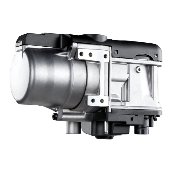
Water Heater
Thermo Top Evo Parking Heater
Installation Documentation
Mercedes Benz A-class (W176) and B-class (W246)
Validity
Manufacturer
Mercedes Benz
Motorisation
Fuel
A 180
Petrol
A 200
Petrol
A 180 CDI
Diesel
A 200 CDI
Diesel
Manufacturer
Mercedes Benz
Motorisation
Fuel
B 180
Petrol
B 200
Petrol
B 180 CDI
Diesel
B 200 CDI
Diesel
SG = Manual transmission
From Model Year 2012
Left-hand drive vehicle
Verified equipment variants: Thermatic / Thermotronic
Not verified:
Total installation time:
Ident. No.: 1318147E_EN
00 0258
Model
A-Class
Transmission type Output in kW
SG
SG
SG
SG
Model
B-Class
Transmission type Output in kW
SG
SG
SG
SG
Headlight washer system
Daytime running lights
Passenger compartment monitoring
Front fog light
approx. 8 hours
Status: 21.11.2012
E
1
Type
EG-BE No. / ABE
W176
e1 * 2007 / 46 * 0928 * ...
Displacement in
cm³
90
1595
115
1595
80
1796
100
1796
Type
EG-BE No. / ABE
W246
e1 * 2007 / 46 * 0751 * ...
Displacement in
cm³
90
1595
115
1595
80
1796
100
1796
Engine code
M 270
M 270
OM 651
OM 651
Engine code
M 270
M 270
OM 651
OM 651
© Webasto Thermo & Comfort SE
Advertisement
Table of Contents

Related Manuals for Webasto Thermo Top Evo


Summary of Contents for Webasto Thermo Top Evo
-
Page 1: Validity
Water Heater Thermo Top Evo Parking Heater 00 0258 Installation Documentation Mercedes Benz A-class (W176) and B-class (W246) Validity Manufacturer Model Type EG-BE No. / ABE Mercedes Benz A-Class W176 e1 * 2007 / 46 * 0928 * ... Motorisation... -
Page 2: Table Of Contents
Remote Option (Telestart) Necessary Components • Basic delivery scope Thermo Top Evo in accordance with price list • Installation kit for Mercedes Benz A-/B-class 2012 Petrol and diesel: 1318146A • Heater control in accordance with price list and upon consultation with end customer •... -
Page 3: Information On Operating And Installation Instructions
Installation and repair may ONLY be carried out by persons trained and VEHICLE INSTALLATION REQUIREMENTS certified in a Webasto training course. NEVER try to install or repair We- 2.1. Scope basto heating or cooling systems if you have not completed a Webasto training course, you do not have the necessary technical skills and you 2.1.1. -
Page 4: Information On Validity
• Crimping pliers for cable lug / tab connector 0.5 - 6mm² • Torque wrench for 2.0 - 10 Nm • Hose clamping pliers • Metric thread-setter kit • Webasto Thermo Test diagnosis with current software Dimensions • All dimensions are in mm. Tightening torque values •... -
Page 5: Preliminary Work
• Remove years that do not apply from the type and duplicate label. • Attach the duplicate label (type label) in the appropriate place in the engine compartment. Heater Installation Location 1 Heater Installation location Ident. No.: 1318147E_EN Status: 21.11.2012 © Webasto Thermo & Comfort SE... -
Page 6: Electrical System
Positive wire Earth wire 1 Positive wire on positive terminal of battery 1 Earth wire at original vehicle earth support point Ident. No.: 1318147E_EN Status: 21.11.2012 © Webasto Thermo & Comfort SE... -
Page 7: Fan Control
ST B Connector of CAN-busmodule Cable colours may vary. 1 Route wire of CAN-bus to the left side of the vehicle 2 Fasten CAN-module with adhesive tape Installing CAN-mod- Ident. No.: 1318147E_EN Status: 21.11.2012 © Webasto Thermo & Comfort SE... - Page 8 Remove window frame, loosen bolts [2x] at position 1 and remove instrument panel. Removing instrument panel Image shows A-class. 2 Unclip CAN-node plug connector Unclipping plug con- nector of CAN-node Ident. No.: 1318147E_EN Status: 21.11.2012 © Webasto Thermo & Comfort SE...
- Page 9 2 Connector of CAN-module (St B) Connec- tion of CAN-bus All vehicles. Image shows B-class. Re-insert plug connector of CAN-node. Rein- stall instrument panel. Complet- ing instru- ment panel Ident. No.: 1318147E_EN Status: 21.11.2012 © Webasto Thermo & Comfort SE...
-
Page 10: Digital Timer
3 Original vehicle bolt Mounting receiver All vehicles 1 Antenna Mounting antenna Temperature sensor T100 HTM Image shows B-class. Fasten temperature sensor 1 with adhesive tape. Installing tempera- ture sensor Ident. No.: 1318147E_EN Status: 21.11.2012 © Webasto Thermo & Comfort SE... -
Page 11: Heater
2 5x15 self-tapping bolt, retaining plate of water connection pieces Mounting water con- nection pieces 1 Hose section, 10 mm dia. clamp [2x] 2 Fuel line Premount- ing fuel line Ident. No.: 1318147E_EN Status: 21.11.2012 © Webasto Thermo & Comfort SE... - Page 12 1 Combustion air pipe 2 51 mm dia. clamp 3 Combustion air silencer 4 M5x16 bolt, flanged nut Premount- ing com- bustion air silencer Ident. No.: 1318147E_EN Status: 21.11.2012 © Webasto Thermo & Comfort SE...
- Page 13 4 Silencer Premount- ing exhaust system 1 Exhaust end section 2 Hose clamp 3 Twist protection 4 M6x16 bolt, spring lockwasher Premount- ing exhaust system D = 1090 Preparing hoses Ident. No.: 1318147E_EN Status: 21.11.2012 © Webasto Thermo & Comfort SE...
- Page 14 3 Large diameter washer, flanged nut 4 Wiring harness of circulating pump Mounting circulating pump All spring clips = 25 mm dia. 1 Connection piece on heater inlet Installing hoses B and C Ident. No.: 1318147E_EN Status: 21.11.2012 © Webasto Thermo & Comfort SE...
-
Page 15: Installing Heater
1 . Mounting heater 1 Exhaust end section 2 Original vehicle bolt [2x] Mounting heater 1 M6x20 bolt, spring lock washer, large di- ameter washer Mounting heater Ident. No.: 1318147E_EN Status: 21.11.2012 © Webasto Thermo & Comfort SE... - Page 16 1 Wiring harness of heater [2x] Attaching wiring har- ness of heater Centrally align exhaust end section 1 with hole and flush with underride protection 2 . Aligning exhaust end section Ident. No.: 1318147E_EN Status: 21.11.2012 © Webasto Thermo & Comfort SE...
-
Page 17: Coolant Circuit For Petrol Vehicles
Hose rout- ing dia- gram All spring clips without a specific designation = 25 mm dia. 1 = Black (sw) rubber isolator All connecting pipes = 18x18 mm dia. Ident. No.: 1318147E_EN Status: 21.11.2012 © Webasto Thermo & Comfort SE... - Page 18 90° 1 Countersink hole with 10mm dia. drill Preparing perforated bracket 1 Install hose bracket Preparing perforated bracket 1 M6x20 bolt, spring lockwasher, original vehicle threaded hole Preparing routing Ident. No.: 1318147E_EN Status: 21.11.2012 © Webasto Thermo & Comfort SE...
- Page 19 1 Circulating pump Connection of hose A 1 Wiring harness of heater 2 38 mm dia. rubber-coated p-clamp 3 10mm spacer, flanged nut Routing in engine compart- ment Ident. No.: 1318147E_EN Status: 21.11.2012 © Webasto Thermo & Comfort SE...
- Page 20 Ensure sufficient distance from neighbouring components. 1 Hose of heat exchanger inlet Connect- ing heat ex- changer inlet 1 Hose on engine outlet Connect- ing engine outlet Ident. No.: 1318147E_EN Status: 21.11.2012 © Webasto Thermo & Comfort SE...
-
Page 21: Coolant Circuit For Diesel Vehicles
Hose rout- ing dia- gram All spring clips without a specific designation = 25 mm dia. 1 = Black (sw) rubber isolator All connecting pipes = 18x18 mm dia. Ident. No.: 1318147E_EN Status: 21.11.2012 © Webasto Thermo & Comfort SE... - Page 22 1 Install hose bracket Preparing perforated bracket 1 Original vehicle bolt 2 Wiring harness of heater 3 Perforated bracket with hose bracket 4 Cable tie Preparing routing Ident. No.: 1318147E_EN Status: 21.11.2012 © Webasto Thermo & Comfort SE...
- Page 23 1 Circulating pump Connection of hose A 1 Wiring harness of heater 2 38 mm dia. rubber-coated p-clamp 3 10mm shim, flanged nut Routing in engine compart- ment Ident. No.: 1318147E_EN Status: 21.11.2012 © Webasto Thermo & Comfort SE...
- Page 24 Ensure sufficient distance from neighbouring components. 1 Hose of heat exchanger inlet Connect- ing heat ex- changer inlet 1 Hose on engine outlet Connect- ing engine outlet Ident. No.: 1318147E_EN Status: 21.11.2012 © Webasto Thermo & Comfort SE...
-
Page 25: Fuel
Cut standpipe 2 at position 1 in the centre of the bead as shown. 2 Cut standpipe to length Petrol Diesel Preparing standpipe 1 Perforated bracket 2 Drill out hole to 9 mm dia. Preparing perforated bracket 90° Ident. No.: 1318147E_EN Status: 21.11.2012 © Webasto Thermo & Comfort SE... - Page 26 (for example Loc- tite 406). 2 Insert clamp Inserting standpipe Affix standpipe 2 from below at position 1 us- ing suitable contact adhesive (for example Loctite 406). Affixing standpipe Ident. No.: 1318147E_EN Status: 21.11.2012 © Webasto Thermo & Comfort SE...
- Page 27 1 Fuel-tank sending unit Fuel ex- traction Insert standpipe 1 and glue in place using suitable contact adhesive (for example Loc- tite 406). 2 Insert clamp Inserting standpipe Ident. No.: 1318147E_EN Status: 21.11.2012 © Webasto Thermo & Comfort SE...
- Page 28 3 in elbow for later instal- lation of wheel-well inner panel. 1 Line holder 2 Fuel line and wiring harness of metering Routing pump lines Ident. No.: 1318147E_EN Status: 21.11.2012 © Webasto Thermo & Comfort SE...
- Page 29 2 Corrugated tube 2 Routing 3 Line holder lines 1 Line holder Routing lines 1 Line holder [3x] Routing lines 1 Line holder [2x] Routing lines Ident. No.: 1318147E_EN Status: 21.11.2012 © Webasto Thermo & Comfort SE...
- Page 30 3 Hose, 10 mm dia. clamp [2x] ing pump 4 Corrugated tube 4 5 Fuel line fuel standpipe 6 Corrugated tube 3 7 Fuel line of heater Ident. No.: 1318147E_EN Status: 21.11.2012 © Webasto Thermo & Comfort SE...
-
Page 31: Final Work
• Mount signboard "Switch off parking heater before refueling" in area of filler neck. • For initial startup and function check, please see installation instructions. Webasto Thermo & Comfort SE Postfach 1410 82199 Gilching Germany Internet: www.webasto.com Technical Extranet: http://dealers.webasto.com Ident. No.: 1318147E_EN Status: 21.11.2012 © Webasto Thermo & Comfort SE... -
Page 32: Installation Instructions For Thermatik
Mercedes Benz A-class (W176) and B-class (W246) Installation Instructions for Thermatik Please remove page in case of manual air-conditioning and add it to the vehicle operating instructions. Note: We recommend matching the heating time to the driving time. Heating time = driving time Example: For a driving time of approx. -
Page 33: Installation Instructions For Thermotronik
Mercedes Benz A-class (W176) and B-class (W246) Installation Instructions for Thermotronik Please remove page in case of manual air-conditioning and add it to the vehicle operating instructions. Note: We recommend matching the heating time to the driving time. Heating time = driving time Example: For a driving time of approx.
Need help?
Do you have a question about the Thermo Top Evo and is the answer not in the manual?
Questions and answers