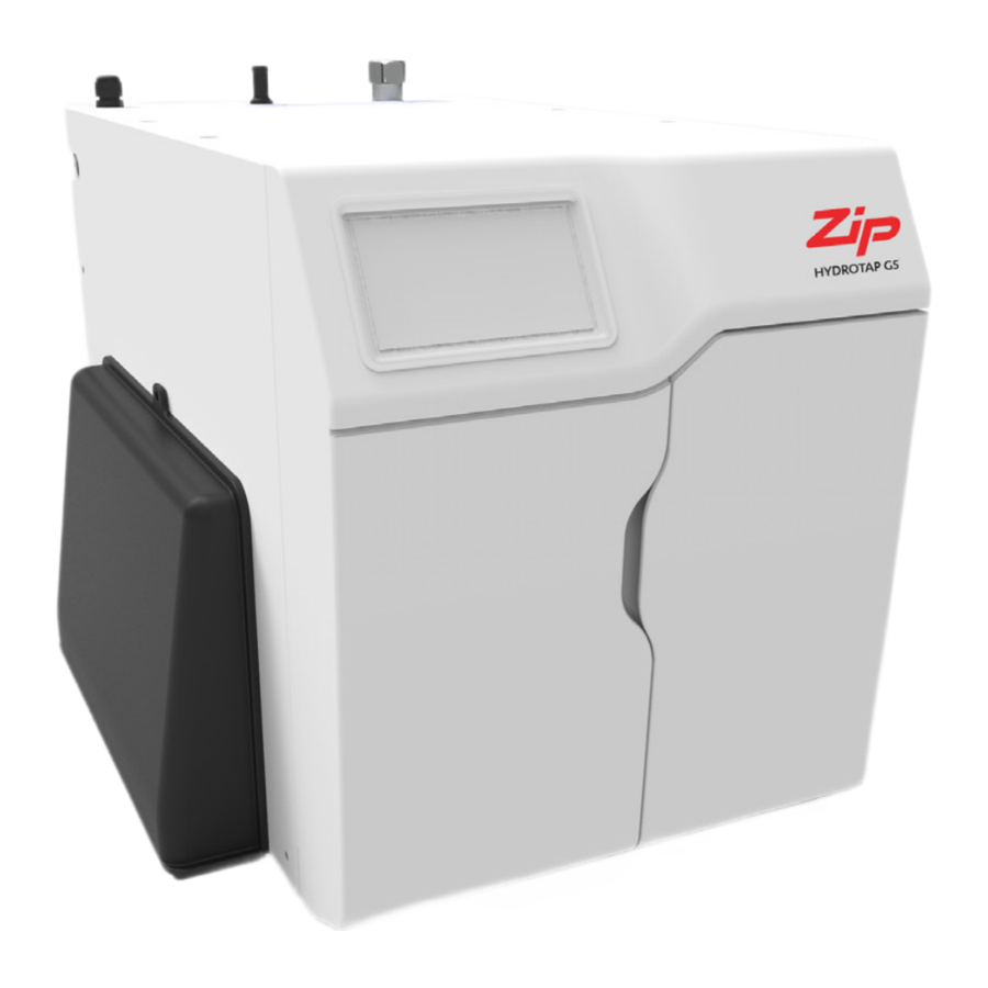
Zip HydroTap G5 Manual
- Quick start installation manual (48 pages) ,
- Installation instructions manual (44 pages) ,
- User manual (44 pages)
Advertisement
- 1 Explanation of symbols
- 2 Technical data
- 3 Parts supplied
- 4 Set up the ventilation
- 5 Fit the carbonation valve
- 6 Connect the water supply
- 7 Install the CO2 cylinder and regulator
- 8 Connect the Command Center
- 9 Commissioning
- 10 Performance data sheets
- 11 IMPORTANT SAFETY INSTRUCTIONS
- 12 WARNINGS & REGULATORY INFORMATION
- 13 Warranty
- 14 Documents / Resources
Explanation of symbols

WARNING

Danger electric shock

CO2 Gas WARNING
Technical data
| Model | 220-240V 50/60Hz | 110-120V 50/60Hz | Dimensions W x D x H inch, (mm) | Weight ib (kg) |
| CS100 | 1.5A (340W) | N/A | 11 (280) x 18.9 (480) x 13.1 (333) With Duct 13 (330) x 18.9 (480) x 13.1 (333) With Duct and Vent Tray 19.7 (500) x 20.5 (520) x 14.7 (373) | 80.5 (36.5) |
| CS Home | N/A | 2.43A (300W) | 11 (280) x 16 (406) x 13.1 (333) | 66 (30) |
Electricity supply requirements
110-120VAC 60Hz or 230VAC 60Hz (for power rating see table above).
| Region | Power outlets required |
| USA | 1x 110-120VAC 60Hz or 230VAC 60Hz outlet |
Water supply connection
1/2" BSP
Water supply requirements
- A cold water supply with a working pressure range of 37 - 100 psi, (250 - 700 kPa) connected via an isolation valve.
- Water inlet connection size is 1/2" BSP. The system shall only be supplied with cold water.
- Potable water should have a minimum TDS (Total Dissolved Solids) of 50 ppm. In areas where the TDS exceeds 150 ppm and where mineral scale could be a problem, consideration should be given to the maintenance required. Adding a water softener or reverse osmosis system should be considered.
A pressure limiting valve must be fitted for mains water pressures above the maximum limits stated above in accordance with local plumbing regulations.
Note: All models have an internal pressure limiting device to reduce the maximum mains regulated pressure protecting the system against pressure surges above 73 psi, (500kPa).
Parts supplied
| Parts supplied with the HydroTap | Chilled & Sparkling |
| Tap | |
| HydroTap faucet |  |
| HydroTap pipes, tubes hoses and fittings | |
| Command Center | |
| Command Center | |
| Mains electrical supply cable | |
| Water supply inlet hose | |
| Water supply inlet adaptor and strainer | |
| Ventilation kit (inc. vent tray for CS100) | |
| Vent kit instructions | |
| Filters | |
| Water filter & instructions | |
| Drip tray | |
| Drip tray kit | Optional |
Note: Mains water isolation valve is not supplied with the kit.
Contact Zip for the full range of consumables and accessories.
Set up the ventilation
Use of tools can be hazardous. Assess the risks before you start.
Use instructions supplied with individual kit parts.
A clearance envelope around all Command Centers must be provided to allow ventilation for the safe and effective use of the HydroTap system.


CS100 models
- Cold air is drawn in through the inlet vent and gap provided by the door buffers.
- Warm air is exhausted through vent tray.
- Inlet vent is mounted over cupboard side, door or floor cut-out (see above).
- Observe 4", (100mm) inlet / outlet vent separation (see above).
The vent tray must be fitted. It provides a safe exhaust for refrigerant gas in the unlikely event of a leak.
Vent tray dimensions WxDxH inch (mm):
19.7 (500) x 20.3-21.8 (515-555) x 1.6 (40)

CS Home models
- Cold air is drawn in through the inlet vent and lower gap provided by the door buffers.
- Inlet vent is mounted over cupboard side, door or floor cut-out.
- Warm air is exhausted through upper gap provided by the door buffers.
All models
If cupboard temperature exceeds 95°F, (35°C) additional ventilation is required.
Contact your Zip service provider for options (including additional vents and fan kit).
Fit the carbonation valve

White tube to SPARKLING outlet of Command Center
Carbonation valve flow adjustment
- Use a 6mm Allen key or a large flat-blade screwdriver to adjust the valve.

- Rotate the adjustment screw anti-clockwise to increase, and clockwise to decrease the flow.
- To measure the set flow rate, use a measuring jug or cup and run the sparkling water for 15 seconds. The HydroTap has a default 15 second dispense time, which will help in your flow rate setup.
- Multiply the amount of water dispensed in 15 seconds by 4 to determine the flow rate in liters per minute.
- The minimum flow rate required is 0.4 gallons, (1.6 liters) per minute.
- If the flow rate is adjusted too high, the carbonation tank will be emptied of water, leaving only CO2 to be dispensed from the tap. This will result in inconsistent flow (spluttering).

Connect the water supply
Valves and fittings must be sealed with PTFE tape if compression seals are not included.
Note Mixer faucet installations also use a 'Tee piece' as part of the water supply plumbing connections, see the Faucet installation instructions supplied with the Mixer to connect the water supply if using the mixer faucet option.
Note correct strainer orientation.

Install the CO2 cylinder and regulator
Be aware of the risks of hazards which could cause harm when handling compressed CO2.
Read the safety warnings at the start of this instruction manual. Assess the risks before starting the installation.

- CO2 cylinders are available in two sizes:
- 1.5lb [24oz] (0.67 kg) [approx. 30 gal. (112 liters)] for residential use.
- 5.0lb [80oz] (2.27 kg) [approx. 100 gal. (378 liters)] for commercial use.
Secure the cylinder
- Ensure there is sufficient space to safely secure the cylinder and regulator.
- Secure cylinder vertically to a robust surface with the hook & loop strap and bracket supplied.
![]()

Fit the regulator and connect the gas hose

- See illustrations above.
- Ensure all mating surfaces are clean and cylinder valve is turned off.
- Turn the regulator OFF, (fully anti-clockwise).
- Check the regulator and hose seals, inside the connectors.
- Carefully screw the regulator onto the cylinder connection.
- Connect the CO2 gas hose to the regulator.
- Connect the CO2 gas hose to the Command Center.
Do not proceed if the seals are damaged.
Take care not to cross thread the regulator, a cross threaded regulator poses a potential hazard.
Adjust the regulator

- Check the regulator control is turned all the way OFF (anti-clockwise).
- Turn the CO2 gas ON using the cylinder valve, (anti-clockwise). (dual-gauge regulator).
- Turn the regulator control (clockwise +) to adjust the outlet pressure to 43.5psi (3.0 bar) on the outlet pressure gauge.
Test for leaks
Care must be taken when working with high pressure carbon dioxide, and in no case should the normal operating pressure of 43.5 psi (3 bar) be exceeded.
- Apply soapy water to the gas connections (see below), using a brush.
- If there is a leak, bubbles will appear.
- In the case of a leak, turn OFF the gas using the cylinder valve, clean away the soapy residue and re-seal the leaking connection.


Test for leaks in these areas
Connect the Command Center
Generic installation instructions
For HydroTap, mixer tap and any optional accessories, use instructions supplied with individual kit components.
Mains power cable
Do not connect to the mains socket until commissioning

USB


HydroTap models are available for either 110-120VAC 50/60Hz or 230VAC 50/60Hz installations. Ensure the electrical power supply at the installation site is suitable for your HydroTap. Use only the power lead supplied with the product.
Connect the power lead to the HydroTap and connect the plug into the electrical power outlet, ensuring both ends are securely engaged to reduce the risk of overheating.

John Guest pipe and fittings

Take care to use correctly, see above
Installation diagrams are for illustrative purposes only.
Hoses are not shown to scale and cannot be lengthened.
Tips for hose connection
- Push the silicone hose over the connector for a minimum of 0.6" (15mm).
- Ensure there a constant fall from the tap down to the command Center.
- Hoses must be trimmed to avoid loops and kinks. Take care when positioning before cutting and make a clean cut straight across the hose, using a sharp blade.

- The hoses must not be under tension when installed.

CS100 models
The foam insulation supplied must be fitted over the WHITE and BLUE pipes

Diagram for illustrative purposes only.
CS Home models
The foam insulation supplied must be fitted over the WHITE and BLUE pipes

Diagram for illustrative purposes only.
Commissioning
The HydroTap Clean process
HydroTap Clean is a first to market cleaning process for HydroTap systems comprised of the HydroTap Clean solution, dosing adaptor and smart firmware. The HydroTap Clean process is automated and gently cleans the chilled and sparkling water paths during the commissioning of a new HydroTap Command Centre.
The HydroTap Clean solution is:
Safe, natural, certified organic, PH neutral, biodegradable solution produced by electrochemically activated water acting like a detergent. HydroTap Clean is also non-corrosive to gently clean the chilled and sparkling internal water paths of your new HydroTap.
Parts supplied
| Parts supplied with the HydroTap Clean kit | Qty |
| HydroTap Clean can adapter (1) (used in filter head) | 1 |
| HydroTap Clean can (2) | 1 |
| HydroTap Clean instructions | 1 |
Parts identification
Do not connect the parts together before carefully reading/following instructions.

Commissioning the Product using the HydroTap Clean can
Turn on the supplies & familiarize yourself with the system
- Connect the mains electrical power cable to the supply.
- Turn the power and water on and check for any leaks.
- Familiarise yourself with the operation of the tap and GUI screen in preparation for use, see the user guide.
- Initial commissioning screen touch Language option.

- Optional screen shown if the commissioning was previously started but not complete (Command Center powered off during process). Otherwise screen will not be shown.


Select the language
- Touch the appropriate button to select the language and units of choice.

- Touch the back arrow to go back to previous menu.
- In the previous menu, touch the arrow to begin the commissioning process.
- Read the commissioning information, touch the forward arrow to go to the next screen.

- (Touch the back arrow to go back to previous menu).


Install the filter cartridge
- Unpack filter cartridge.
- Remove dust cap and set aside in a clean area for use later.
- Write today's date where shown on the label.
- Avoid touching the filter o-rings and filter opening as this may cause bacterial contamination of the cartridge.
- Moisten the o-rings with water.
![]()
- Open the filter door on the Command Center.
- Push the new cartridge up into the filter head.
![]()
- Turn the cartridge a quarter turn to the right until it comes to a complete stop and locks.


Set the date/time & drain away options
- Touch the date and time, use "-" or "+" to make adjustments. When ready, touch the arrow to continue.

- Select 'Sink / Container' or 'Drip tray' depending on the model, see below.


- Select 'Drip tray' if the HydroTap is mounted on a drip tray.
- Select 'Sink / Container' if the HydroTap is mounted such that the waste water dispenses into a sink, or container.
- Note This selection will determine if water is dispensed automatically or requires operation of the tap during the tank flush process.
- Touch the arrow to continue.


Filter flush
- Follow the steps on-screen to flush the filter.

- Open filter door & uncoil flush line.
![]()
- Direct flush line into bucket.
- Place a cloth or towel under the filter cartridge to catch any water that may spill.
- Open the shut off valve.
![]()
- Start filter flush.
![]()
- Once the filter flush is finished, close the shut off valve.
![]()
- Wipe up any spills.
- Close the door to secure the appliance.


System priming
- Read the on screen information.

- For sparkling models disconnect the CO2 bottle or turn off the CO2 regulator (see the User guide).
- Confirm on screen.
- Touch the run arrow to go to the next screen.
- Monitor the on screen information.

- Note if 'drip tray' has been selected on the drain away option (see "Set the date/time & drain away options" section) and auto dispense is disabled on entry into this screen; the screen prompts the user to dispense using the tap during the process.


Cleaning preparation
- Read the on screen information.

- Place a cloth under the filter.
- Remove the filter, refit the dust cap, and set aside in a clean environment.
![]()
- Check the adapter seal is present and correctly positioned in the adapter.
- Install the HydroTap Clean adapter (1) into the filter head.

- Turn the adapter a quarter turn to the right until it comes to a stop and locks.
- Remove the lid from the HydroTap Clean can (2).
![]()
- Screw the HydroTap Clean can (2) into the adapter (already installed into the filter head).

- Confirm installation of the HydroTap Clean can by selecting YES on the screen.


Cleaning
- Read the on screen information.

- CS systems offer just a cleaning process.
- Touch the green arrow to run.
- Cleaning process begins.

- Monitor the on screen information.
- Note This is automatic unless 'Font' was selected in the drain away option selection screen (see "Set the date/time & drain away options" section). In this case a manual dispense action may be requested.
- Read the on screen information and instructions.
- Note When the cleaning process completes there is an opportunity to re-install the filter.
- This screen is shown after completion of the cleaning processes.

- Unscrew the HydroTap Clean can (2).
![]()
- Ensure to hold the adapter in place while unscrewing the can.


- Remove the HydroTap Clean adapter (1) from filter head.
![]()
- Remove the dust cap and re-install the filter.
![]()
- Touch forward arrow on screen to continue.


Tank flush
- Read the on screen information and instructions.

- Touch the green arrow to run.
- Note For all models, the on screen cycle counter displays the number of remaining cycles in the tank flush process.
- Monitor the on screen information.
- For CS models the sparkling tank will cycle once on both the chilled and sparkling reticulation.

- For CS models:
- Read the on screen information.
- Ensure that the CO2 cylinder is connected and if supplied with an adjustable regulator, set to 43.5psi (3.0 bar).

- Touch the green arrow to run.

- CO2 life settings should be adjusted for the size of the CO2 bottle connected. (see the User guide or Online Installation and User guide.
- Use the skip arrow to end the CO2 purge process prematurely if all water has been purged and only gas can be heard coming from the tap.


Backflow Prevention
All HydroTap models that have sparkling/carbonated water functionality include the following integral Backflow Prevention.
Main Water Inlet
The Dual Check Valve (DCV) on the Mains Water inlet connection is designed to ensure a uniform direction of flow throughout the HydroTap. This valve configuration eliminates any possible contamination of the mains water supply, caused by backflow or back siphonage and is a secondary safety feature in the case of the inlet safety solenoid. The DCV also maintains a constant pressure upstream of the inlet safety solenoid. There are two (2) operating principles:

- Firstly, one check valve will still act, even if the other is jammed open;
- Secondly, the closure of one valve reduces the pressure differential across the other, allowing a more reliable seal and avoiding the possibility of minor leakage.
The HydroTap MUST NOT be operated without the Dual Check Valves in place.
Internal Carbonator
There are two (2) Check Valves on the internal Carbonator. The Check Valves ensure the flow of CO2 gas and water is maintained in one direction, into the carbonator. These valves help to maintain the pressure needed to ensure the gas remains dissolved in the water while inside the carbonator. The Check Valves are designed to stop any backflow of gas and/or water out of the internal carbonator.

In addition to the HydroTap's integral Backflow prevention
Some authorities require additional Backflow Prevention to be installed to comply with the Local, State or Federal plumbing code requirements. Both the Universal Plumbing Code (UPC) and National Standard Plumbing Code (NSPC) require the use of an American Society of Sanitary Engineers (ASSE) 1022 backflow preventer on the supply to carbonators under UPC 603.5.12 and NSPC 10.5.8.
UPC: "Potable water supply to beverage dispensers, carbonated beverage dispensers, or coffee machines shall be protected by an air gap or a vented backflow preventer in accordance with ASSE 1022. For carbonated beverage dispensers, piping material installed downstream of the backflow preventer shall not be affected by carbon dioxide gas".
NSPC: "The water supply to a carbonated beverage dispenser shall be protected against backflow with an integral backflow preventer conforming to ASSE 1022 or an air gap. Carbonated beverage dispensers and carbonated beverage dispensing systems without an integral backflow preventer conforming to ASSE 1022 or an air gap shall have the water supply protected with double check valve and atmospheric vent conforming to ASSE 1022."
In order to comply with this requirement the Installer MUST install an ASSE 1022 approved backflow device on the water supply leading to the HydroTap. This will ensure compliance with the requirement to protect the potable water supply to the carbonated beverage dispenser.
Performance data sheets
Performance Data Sheet
Zip HydroTap G5 CS100 with ARC XX, CUBE XX, Classic XX, Wave XX, Classic Plus XX, Elite Plus XX, ARC Plus XX, and CUBE Plus XX faucets.
Manufacturer: Zip Heaters (Aust) Pty. Ltd
67 Allingham Street, Condell Park NSW 2200 Australia
Distributed in US and Canada by: Culligan International Company
Call Zip's US distributor Culligan International Company on US
Toll Free 1-833-233-2358 for assistance, service, spare parts or enquiries
Testing Conditions and Results:
Flow Rate: 1.5 gpm, Pressure: 60 psig ± 3, Temperature: 68 ± 5°F, Capacity: 1,800 gallons, pH: 7.5 ± 0.5
Operating Conditions
Minimum Working Pressure: 37 psi (2.60 kg/cm²)
Maximum Working Pressure: 100 psi (7.03 kg/cm²)
Minimum Operating Temperature: 41°F (5°C)
Maximum Operating Temperature: 95°F (35°C)
Electrical Characteristics: 220-240V 50/60Hz
Replacement Cartridge: 1.5Z-LS (Culligan P/N 01034277)
Operating TDS: 50 ppm – 150 ppm
Cartridges manufactured for Zip by Pentair Everpure, EPA Est. No. 002623-IL-002. Replacement cartridges can be purchased from your local Culligan dealer, Zip dealer or other Zip approved distributors.
Substance Reduction
The system, used in conjunction with the above-mentioned filter cartridge, has been certified by IAPMO R&T according to NSF/ANSI 42 and NSF/ANSI 53 for reduction of the substances listed below. The concentration of the indicated substances in water entering the system was reduced to a concentration less than or equal to the permissible limit for water leaving the system as specified in NSF/ ANSI 42 and NSF/ANSI 53.
| Substance | Average Influent Challenge Concentration | Max. Permissible Product Requirements | Reduction Requirements | Average Reduction |
| NSF/ANSI 42 – Aesthetic Effects | ||||
| Bacteriostatic Effects | Unit passes NSF/ANSI 42 for Bacteriostatic effects. | |||
| Chlorine, Taste and Odor | 2.0 mg/L ± 10% | ≥ 50% | 97.4% | |
| Nominal Particulate Reduction, Class I (≥ 0.5 µm to < 1 µm) | 10,000/mL | ≥ 85% | 99.3% | |
| NSF/ANSI 53 – Health Effects | ||||
| Cyst | Minimum 50,000/L | ≥ 99.95% | 99.99% | |
| Lead, pH 8.5 | 0.15 mg/L ± 10% | 0.005 mg/L | ≥ 96.67% | 98.9% |
| Lead, pH 6.5 | 0.15 mg/L ± 10% | 0.005 mg/L | ≥ 96.67% | 99.3% |
*Available in a range of premium metallic finishes. XX refers to the specific finish of the faucet.
Do not use with water that is microbiologically unsafe or of unknown quality without adequate disinfection before or after the system. The term 'bacteriostatic' means that the system limits the passage or growth of bacteria that may already exist in the incoming water. It does not mean that the water leaving the system is safer to drink than the water entering the system.
Systems certified for cyst reduction may be used on disinfected waters that may contain filterable cysts.
See the installation manual for installation, maintenance requirements and warranty.
Performance Indicator: Filter Light on LED faucet. Full text notification on LCD display.
To maintain product certification and ensure uniform performance, the product is retested on a consistent basis.
Performance Data Sheet
Zip HydroTap G5 CS Home with ARC XX, CUBE XX, Classic XX, Wave XX, Classic Plus XX, Elite Plus XX, ARC Plus XX, and CUBE Plus XX faucets.
Manufacturer: Zip Heaters (Aust) Pty. Ltd
67 Allingham Street, Condell Park NSW 2200 Australia
Distributed in US and Canada by: Culligan International Company
Call Zip's US distributor Culligan International Company on US
Toll Free 1-833-233-2358 for assistance, service, spare parts or enquiries.
Testing Conditions and Results:
Flow Rate: 1 gpm, Pressure: 60 psig ± 3, Temperature: 68 ± 5°F, Capacity: 1,100 gallons, pH: 7.5 ± 0.5
Operating Conditions
Minimum Working Pressure: 37 psi (2.60 kg/cm²)
Maximum Working Pressure: 100 psi (7.03 kg/cm²)
Minimum Operating Temperature: 41°F (5°C)
Maximum Operating Temperature: 95°F (35°C)
Electrical Characteristics: 110-120V 50/60Hz
Replacement Cartridge: 1Z-LS (Culligan P/N 01034276)
Operating TDS: 50 ppm – 150 ppm
Cartridges manufactured for Zip by Pentair Everpure, EPA Est. No. 002623-IL-002. Replacement cartridges can be purchased from your local Culligan dealer, Zip dealer or other Zip approved distributors.
Substance Reduction
The system, used in conjunction with the above-mentioned filter cartridge, has been certified by IAPMO R&T according to NSF/ANSI 42 and NSF/ANSI 53 for reduction of the substances listed below. The concentration of the indicated substances in water entering the system was reduced to a concentration less than or equal to the permissible limit for water leaving the system as specified in NSF/ ANSI 42 and NSF/ANSI 53.
| Substance | Average Influent Challenge Concentration | Max. Permissible Product Requirements | Reduction Requirements | Average Reduction |
| NSF/ANSI 42 – Aesthetic Effects | ||||
| Bacteriostatic Effects | Unit passes NSF/ANSI 42 for Bacteriostatic effects. | |||
| Chlorine, Taste and Odor | 2.0 mg/L ± 10% | ≥ 50% | 97.4% | |
| Nominal Particulate Reduction, Class I (≥ 0.5 µm to < 1 µm) | 10,000/mL | ≥ 85% | 99.3% | |
| NSF/ANSI 53 – Health Effects | ||||
| Cyst | Minimum 50,000/L | ≥ 99.95% | 99.99% | |
| Lead, pH 8.5 | 0.15 mg/L ± 10% | 0.005 mg/L | ≥ 96.67% | 98.9% |
| Lead, pH 6.5 | 0.15 mg/L ± 10% | 0.005 mg/L | ≥ 96.67% | 99.3% |
*Available in a range of premium metallic finishes. XX refers to the specific finish of the faucet.
Do not use with water that is microbiologically unsafe or of unknown quality without adequate disinfection before or after the system. The term 'bacteriostatic' means that the system limits the passage or growth of bacteria that may already exist in the incoming water. It does not mean that the water leaving the system is safer to drink than the water entering the system.
Systems certified for cyst reduction may be used on disinfected waters that may contain filterable cysts.
See the installation manual for installation, maintenance requirements and warranty.
Performance Indicator: Filter Light on LED faucet. Full text notification on LCD display.
To maintain product certification and ensure uniform performance, the product is retested on a consistent basis.
IMPORTANT SAFETY INSTRUCTIONS
Compliance
All Plumbing and Electrical connections must comply with local, state and federal codes.
All Plumbing and Electrical connections must be made in accordance with local regulations.
Ensure the electrical power supply at the installation site is suitable for your HydroTap.
HydroTap models are rated for the following installations:
- Commercial - 220-240VAC 50/60Hz.
- Residential (120V) - 110-120VAC 50/60Hz.
Safety
This appliance is not intended for use by children under 8 years or persons (including children under 8 years) with reduced physical, sensory or mental capabilities, or lack of experience and knowledge, unless they have been given supervision or instruction concerning the use of the appliance by a person responsible for their safety. Children should be supervised to ensure that they do not play with the appliance.
Ventilation
Keep ventilation openings, in the appliance enclosure or in the built-in structure, clear of obstruction.
Do not use mechanical devices or other means to accelerate the defrosting process, other than those recommended by the manufacturer.
Do not store explosive substances such as aerosol cans with a flammable propellant in this appliance.
CO2
- Keep out of reach of children.
- Use according to MSDS (material safety data sheet).
- Pressurized container. Contains gas under pressure, may explode if heated.
- Protect from sunlight.
- Do not expose to temperatures exceeding 122ºF, (50ºC).
- Do not expose to naked flame or any incandescent material.
- Do not pierce or burn, even after use. Avoid shock.
- High concentration of gas may cause asphyxiation.
- Use only in an upright position.
- The cylinder must be used with the supplied pressure regulator.
- Store in a location with a volume no less than 65 cubic yards, (50 cubic meters) for each 5 lb, (2.27kg) cylinder.
- If more than 1 gas cylinder containing CO2 is present within the same location, the recommended ventilated area should be in proportion to the number of gas cylinders stored in that location. A ventilated area is a non-enclosed area which could include the kitchen, living room etc.
- Refer to the gas cylinder and MSDS for a complete list of warnings (www.na.zipwater.com).
Qualifications
To avoid hazards, all installation procedures must be carried out by a suitably qualified tradesperson. The power cable and power outlet must be in a safe visible position for connection.
Venting
Sometimes steam and / or boiling water droplets may discharge through a vent outlet on the tap. If not using the font, ensure the tap body is located so the tap outlet safely dispenses into the sink bowl.
Lifting
Take care when lifting. The Command Center may exceed safe lifting limits. If you feel this is beyond your personal capabilities, please seek assistance with the lift. The weight of the Command Center is marked on the packaging. Do not lift the Command Center by the front cover or any of its connections.
Airflow
The ambient operating temperatures, when installed in a cabinet, must be between 41 - 95ºF, (5 - 35ºC). The system will operate satisfactorily only with proper air ventilation. Air gaps of 2",(50mm) on each side, and 8",(200mm) above must be provided. See "Set up the ventilation" section for correct ventilation details.
Frost protection
If the HydroTap is located where the ambient air temperature could fall below 41ºF, (5ºC) when the system is not in use, do not turn off the Command Center electrically. This safeguard does not offer the same protection to the connecting pipework and fittings.
Application
The HydroTap G5 Home series is intended to be used in household and similar applications such as:
- Staff kitchen areas in shops, offices and other working environments;
- Farm houses and by clients in hotels, motels and other residential type environments;
- Bed and breakfast type environments;
- Catering and similar non-retail applications.
Compressed gas warning - HydroTap Clean can
- Read label before use.
- Keep out of reach of children.
- Use according to SDS (safety data sheet).
- Pressurised container. Contains gas under pressure, may explode if heated.
- Protect from sunlight.
- Do not expose to temperatures exceeding 122ºF, (50ºC).
- Do not expose to naked flame or any incandescent material.
- Do not pierce or burn, even after use.
- Avoid shock.
- SDS is available for download at www.na.zipwater.com
First aid
- For advice contact a Poison Control Information Centre.
- USA (+1) 1-800-222-1222.
WARNINGS & REGULATORY INFORMATION
![warning]() For continued safety of this appliance it must be installed, operated and maintained in accordance with the manufacturer's instructions.
For continued safety of this appliance it must be installed, operated and maintained in accordance with the manufacturer's instructions.![shock hazard]() The Zip HydroTap must be grounded. Grounding is provided via the supplied power cord. The resistance of the ground connection to each exposed metal part must be less than 1Ω. Use the power cable supplied. It is the responsibility of the installer to ensure the power point is grounded.
The Zip HydroTap must be grounded. Grounding is provided via the supplied power cord. The resistance of the ground connection to each exposed metal part must be less than 1Ω. Use the power cable supplied. It is the responsibility of the installer to ensure the power point is grounded.
![]()
- All installation and service work must be completed by trained and suitably qualified tradespeople. Faulty operation due to unqualified persons working on this product may void warranty coverage.
- As the installer, it is your responsibility to supply and install all valves as required by local regulations and relevant standards.
- Do not remove the cover of the appliance under any circumstances without first isolating the appliance from the power supply.
- The new hose sets supplied with the product must be used. Do not re-use old hose sets.
- Never locate the system near, or clean with water jets.
- Do not expose the Zip HydroTap to the elements of nature.
- Due to the process of continuous improvement, Zip reserves the right to change details mentioned in this manual, without notice.
- If this device is not maintained and operated as specified in this document, there is a risk of exposure to contaminants.
- When dispensing hot water, the device can create a scald hazard.
- Use of tools can be hazardous. Assess the risks before you start.
- clearance envelope around all Command Centers must be provided to allow adequate ventilation for the safe and effective use of the HydroTap system.
- The vent tray, if provided, must be fitted. It provides a safe exhaust for refrigerant gas in the unlikely event of a leak.
- Valve and fitting threads must be sealed appropriately with PTFE tape where compression seals are not provided.
- Always flush new filter before use. Do not over tighten plumbing and hose connections.
- Braided hoses supplied cannot be lengthened.
- Be aware of the risks of hazards which could cause harm when handling compressed CO2. Assess the risks before starting the installation.
- Do not proceed with a CO2 cylinder change if the seals are damaged. Take care not to cross thread the regulator, a cross threaded regulator poses a potential hazard.
- Care must be taken when working with high pressure carbon dioxide, and in no case should the normal operating pressure of 43.5psi (3 bar) be exceeded.
- The power cord and general power outlet must be in a safe and accessible position after installation. When positioning the appliance, ensure the power supply cord is not trapped or damaged. If the power supply cord is damaged it must be replaced by a Zip service provider or a qualified electrician.
- Do not locate multiple portable socket-outlets or portable power supplies at the rear of the appliance.
- For safe operation, the HydroTap is designed to be installed, commissioned and used within 48 hours. Should the HydroTap not be required for an extended period of time (72 hours or more), do not fill and commission the HydroTap until ready for first use.
- For water taste and quality reasons, following any non-use period of more than 72 hours, Zip recommends to perform a system flush. Failure to flush the system may affect water quality.
Warranty
How To Register?
Zip Products must be registered online at https://www.us.zipwater.com
Dispute Resolution
If the Zip Customer is not satisfied with the warranty service, he or she must submit a claim in writing to Zip's Dispute Settlement Representative at Culligan International Company, d/b/a Zip Water, 9399 W Higgins Rd, Rosemont, IL 60018.
How to Obtain Warranty Service for The Zip Product?
For service for all products under this Limited Warranty, or for product information, please contact Zip Service at service@na.zipwater.com or by calling 1-833-233-2358.
Manufactured by Zip Heaters (Aust) Pty Ltd
67 - 77 Allingham Street,
Condell Park NSW 2200
Australia
Distributed in US and Canada by: Culligan International Company
9399 West Higgins Road, Suite 1100
Rosemont, IL 60018
www.na.zipwater.com
Call US Toll Free 1-833-233-2358 for assistance, service, spare parts or enquiries.
Documents / Resources
References

Download manual
Here you can download full pdf version of manual, it may contain additional safety instructions, warranty information, FCC rules, etc.
Advertisement


Need help?
Do you have a question about the HydroTap G5 and is the answer not in the manual?
Questions and answers