Zip HydroTap G5 Quick Start Installation Manual
Command centre boiling, chilled & sparkling models
Hide thumbs
Also See for HydroTap G5:
- Quick start manual ,
- Quick start installation manual (48 pages) ,
- Installation instructions manual (44 pages)
Table of Contents
Advertisement
Quick Links
Advertisement
Table of Contents

Related Manuals for Zip HydroTap G5


Summary of Contents for Zip HydroTap G5
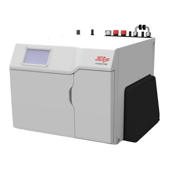
- Page 1 HydroTap G5 Command Centre Boiling, Chilled & Sparkling models AFFIX PRODUCT LABEL HERE Australia Visit our website to download the manuals Quick Start Installation Guide 807119 v1.00 01.21 G5 BCS Quick Start Guide...
-
Page 2: Table Of Contents
Table of contents SECTION 1: Using these instructions ..............3 SECTION 2: IMPORTANT SAFETY INSTRUCTIONS ..........4 SECTION 3: WARNINGS & REGULATORY INFORMATION ........6 SECTION 4: Technical data ................8 SECTION 5: Parts supplied, consumables and accessories ......10 SECTION 6: Set up the ventilation ..............11 SECTION 8: Connect the water supply ............. -
Page 3: Section 1: Using These Instructions
SECTION 1: Using these instructions Before you start This document is a Quick Start Installation Guide. For further details on installing and operating your HydroTap download & read the Command Centre installation and user instructions , which can be found online at: (Australia) www.zipwater.com (UK) -
Page 4: Section 2: Important Safety Instructions
Children should be supervised to ensure that they do not play with the appliance. Refrigerant The Zip HydroTap Command Centre range uses either HIGHLY FLAMMABLE R290, R600a or R134A refrigerant under pressure. Check the rating plate or contact Zip before commencing work. - Page 5 Do not lift the Command Centre by the front cover or any of its connections. Airflow The Zip HydroTap operates within the ambient temperature range 5ºC - 35ºC. Proper air circulation must be provided. The system will operate satisfactorily only if the recommended air gaps are provided. The vent kit supplied must be fitted.
-
Page 6: Section 3: Warnings & Regulatory Information
• Connect only to a potable (wholesome, cat1) mains water supply. • Never locate the system near, or clean with water jets. • Do not expose the Zip HydroTap to the elements of nature. • The booster complies with protection class IP 20. - Page 7 When positioning the appliance, ensure the power supply cord is not trapped or damaged. If the power supply cord is damaged it must be replaced by a Zip service provider or a qualified electrician. • Do not locate multiple portable socket-outlets or portable power supplies at the rear of the appliance.
-
Page 8: Section 4: Technical Data
SECTION 4: Technical data Power rating Dimensions Weight Model W x D x H (mm) (kg) BCS100 2.15 + 2.20* 450 (500) x 470 x 333 BCS100 H BCS60 2.15 450 (500) x 470 x 333 BCS60 H BCS30 1.96 + 2.20* 339 x 460 x 333 BCS30 H BCS20... - Page 9 SECTION 4: Technical data Water supply connection 1/2” BSP (G1/2) Water supply pressure requirements Min - Max pressure, kPA (bar) Component Australia HydroTap 170 (1.7) - 700 (7.0) 170 (1.7) - 500 (5.0) Sparkling HydroTap 250 (2.5 ) - 700 (7.0) 250 (2.5) - 500 (5.0) Vented Mixer Tap 300 (3.0) - 700 (7.0)
-
Page 10: Section 5: Parts Supplied, Consumables And Accessories
* supplied with 1.2kg cylinder and adjustable regulator combination. Note: Mains water isolation valve is not supplied with the kit. Contact Zip for the full range of consumables and accessories. Quick Start Installation Guide 807119 v1.00 01.21 G5 BCS Quick Start Guide... -
Page 11: Section 6: Set Up The Ventilation
SECTION 6: Set up the ventilation Use of tools can be hazardous. Assess the risks before you start. Use instructions supplied with individual kit parts. A clearance envelope around all Command Centres must be provided to allow ventilation for the safe and effective use of the HydroTap system. - Page 12 SECTION 6: Set up the ventilation BCS60 and BCS100 models • Cold air is drawn in through the inlet vent and gap provided by the door buffers. • Inlet vent is mounted over cupboard side, door or floor cut-out. • Warm air is exhausted through vent tray. •...
- Page 13 (supplied) Air inlet All models If cupboard temperature exceeds 35°C, additional ventilation is required. Contact your Zip service provider for options (including additional vents and fan kit). Quick Start Installation Guide 807119 v1.00 01.21 G5 BCS Quick Start Guide...
- Page 14 SECTION 7: Fit the carbonation valve Classic, Wave, Celsius Other Avoid Classic Plus, AiO Arc sparkling Elite White tube to SPARKLING outlet of Command Centre Carbonation valve flow adjustment • Use a 6mm Allen key or a large flat-blade screwdriver to adjust the valve.
-
Page 15: Section 8: Connect The Water Supply
SECTION 8: Connect the water supply Valves and fittings must be sealed with PTFE tape if compression seals are not included. Note Mixer tap installations also use a ‘tee piece’ as part of the water supply plumbing connections, see the Tap installation instructions supplied with the Mixer Tap to connect the water supply if using the mixer tap option. -
Page 16: Section 9: Set The Bypass & Install The Limescale Filter
SECTION 9: Set the bypass & install the limescale filter Available as optional accessory - UK only. For filter head and scale filter installation use the guide supplied with the filter head and filter respectively. Flush filter before use. Water Water Bypass in Bypass out... -
Page 17: Section 10: Fit The Booster
SECTION 10: Fit the booster Supplied with selected models, or available as an optional accessory. Booster 10⁰ 15⁰ Note: Take care not to break the clips when removing or installing the booster. Quick Start Installation Guide 807119 v1.00 01.21 G5 BCS Quick Start Guide... - Page 18 SECTION 11: Connect the Booster Booster Connect electricity Do not switch on electrical power until commissioning. Do not over tighten hose connections. Braided hoses supplied cannot be lengthened. Cold water into booster, Hot water out of booster, connect to Command Centre connect to Command Centre BYPASS OUT BYPASS IN...
-
Page 19: Section 12: Install The Co2 Cylinder And Regulator
SECTION 12: Install the CO2 cylinder and regulator Be aware of the risks of hazards which could cause harm when handling compressed CO2. Read the important safety instructions at the start of this instruction manual. Assess the risks before starting the installation. Secure the cylinder Ensure these is sufficient space to safely secure the cylinder and regulator. - Page 20 SECTION 12: Install the CO2 cylinder and regulator CO2 regulator identification Universal G5 regulator Cylinder pressure Braided hose Outlet connection pressure Regulator control knob Cylinder connection 1.2kg cylinder non-adjustable regulator Regulator control knob Braided hose connection Cylinder connection Quick Start Installation Guide 807119 v1.00 01.21 G5 BCS Quick Start Guide...
- Page 21 SECTION 12: Install the CO2 cylinder and regulator Fit the regulator and connect the gas hose • Ensure all mating surfaces are clean. • Turn the regulator OFF. • Check the regulator and hose seals, inside the connectors. • Connect the gas hose to the regulator. •...
- Page 22 SECTION 12: Install the CO2 cylinder and regulator Adjust the regulator Universal G5 regulator Outlet pressure Regulator control knob • Check the regulator is turned all the way OFF (anti-clockwise). • Turn the gas ON using the cylinder valve (2.64Kg cylinder), (anti-clockwise). •...
- Page 23 SECTION 12: Install the CO2 cylinder and regulator Test for leaks Care must be taken when working with high pressure carbon dioxide, and in no case should the normal operating pressure of 3.0 bar be exceeded. • Apply soapy water to the gas connections (see below), using a brush. •...
-
Page 24: Section 13: Connect The Command Centre
SECTION 13: Connect the Command Centre Generic installation instructions For HydroTap, mixer tap and any optional accessories, use instructions supplied with individual kit components. Mains power cable Braided hose HydroTap Command Connections key Centre Installation diagrams are for illustrative purposes only. Hoses are not shown to scale and cannot be lengthened. - Page 25 SECTION 13: Connect the Command Centre Booster (selected models) and BCS60, BCS100 models limescale filter (optional) BYPASS VENT BYPASS Zip Vented Mixer Tap Fit foam insulation connections Mains (supplied) to the (if supplied) Water BLUE and WHITE pipes CLEAR BLUE...
- Page 26 SECTION 13: Connect the Command Centre BCS20, BCS30, Booster (selected models) and BCS Home models limescale filter (optional) BCS comm Zip Vented Mixer Tap connections Mains Fit foam insulation (if supplied) Water CHILLED SPARKLING MAINS MIXER MIXER BOILING BYPASS VENT...
-
Page 27: Section 14: Commissioning
SECTION 14: Commissioning User Guide Unpack, moisten o-rings & fit filter Boiling calibration Filter flush Boost enable Connect electricity if booster fitted Power off Flush 10 Litres through Monitor display screen Pull levers forward Power on TANK FLUSH 12:12 PM Follow the prompts to flush fresh water through the tank/s 3 times as shown by the cycle counter/s. - Page 28 ABN 46 000 578 727 67 - 77 Allingham Street, Condell Park NSW 2200 Postal: Locked Bag 80, Bankstown 1885 Australia Tel (+612) 9796 3100 Free call 1800 947 827 (1800 ZIP TAP) www.zipwater.com WMKA00099 AU02691 AS 3498 Zip Water UK Trafalgar House, Rash’s Green,...
Need help?
Do you have a question about the HydroTap G5 and is the answer not in the manual?
Questions and answers