Table of Contents
Advertisement
Quick Links
Service Manual
EN
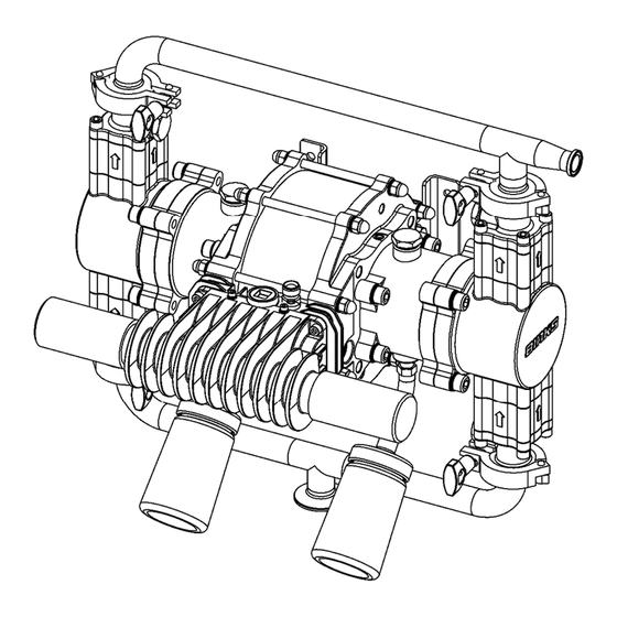
Maple 20AFP Pump
Model 104016
IMPORTANT! DO NOT DESTROY
It is the Customer's responsibility to have all operators and service personnel read and
understand this manual.
Contact your local Carlisle Fluid Technologies representative for additional copies of this
manual.
READ ALL INSTRUCTIONS BEFORE OPERATING THIS PRODUCT
Advertisement
Table of Contents

Related Manuals for Carlisle BINKS Maple 20AFP


Summary of Contents for Carlisle BINKS Maple 20AFP
- Page 1 IMPORTANT! DO NOT DESTROY It is the Customer's responsibility to have all operators and service personnel read and understand this manual. Contact your local Carlisle Fluid Technologies representative for additional copies of this manual. READ ALL INSTRUCTIONS BEFORE OPERATING THIS PRODUCT...
- Page 2 Instruction Manual 77-3337 R1.0 Page 2 of 28 Issue: 3.1...
- Page 3 Instruction Manual Index Section General Description Operating Principle Specifications Dimensions and Mounting Details Important Safety Information Installation - General Parts Lists Main Pump Parts Lists Air Motor Parts Lists Fluid Section Parts Lists Reference Maintenance – Air Motor Assembly Procedure Maintenance –...
- Page 4 Instruction Manual General Description – Section 1.1 High Quality materials and surface treatments are used in the construction of this pump to ensure both extended operational life and good future appearance. The Maple pump is a horizontal piston pump for pumping Solvent / Waterborne Paints, Solvents and other suitable materials.
- Page 5 Instruction Manual Operating Principle – Section 1.2 The Assembly comprises of:- Central Air Piston and ‘change over’ Poppet valves 2 off Quick Exhaust and muffler assembly 2 off Dynamic Chambers and Fluid Pistons 2 off Fluid Pressure Chambers each complete with Suction and Pressure Ball Check Valve Assemblies ...
-
Page 6: Specification
Instruction Manual Specification – Section 1.3 Specification 40 mm Pump Nominal Stroke 1.57 ins Pump Ratio 4.2:1 0.475 Litres Nominal Flow Volume / Cycle 0.125 US Gall Fluid Output @ 60 cycles/min 28.4 Litres / min 7.5 US Gall / min Maximum Recommended Continuous Cycle Rate 20 Cycles /min Maximum Recommended Intermittent Cycle Rate... - Page 7 Instruction Manual Dimensions and Mounting Details – Section 1.4 For Piped Exhaust Air, remove mufflers and add 192803 Plug and Hose Adapter 192779 for 1” NB Hose or 192820 for 1 ¼” NB Hose. Note: For Pump fluid pressures above 13 bar use 1 ¼” NB 77-3337 R1.0 Page 7 of 28 Issue: 3.1...
- Page 8 Instruction Manual Important Safety Information - Section 2.1 Directions for Working Safety This Product has been constructed according to advanced technological standards and is operationally reliable. Damage may, however, result if it is used incorrectly by untrained persons or used for purposes other than those for which it was constructed. The locally current regulations for safety and prevention of accidents are valid for the operation of this product under all circumstances.
- Page 9 Instruction Manual Important Safety Information - Section 2.1 Fire, Explosion and Electric Shock Hazard Improper grounding, poor ventilation, open flames or sparks can cause a hazardous condition and result in a fire, explosion, or electric shock. When installed and operated in accordance with its instructions, the pump is approved for operation in Zone 1 (Europe) & Division 1 (North America), hazardous locations.
-
Page 10: Installation - Section
Instruction Manual Installation – Section 3.1 Mount the pump securely and position the pump at a convenient height (below the lid height of the paint container), to allow for maintenance, visual observation, and periodic inspection. The wall mount bracket is included with all pumps. Exhaust silencer kits are available for these pumps if the air exhaust is required to be piped away from the pump rather than exhausting locally through the mufflers. -
Page 11: Parts List - Section
Instruction Manual Parts List – Section 4.1 Parts List - 104016 Main Pump Assembly ITEM PART No DESCRIPTION REMARKS ------ AIR MOTOR ASSEMBLY ------ FLUID SECTION ASSEMBLY 192777 MUFFLER 192845 INLET MANIFOLD 192846 OUTLET MANIFOLD 192009 SANITARY CLAMP 192206 SANITARY GASKET 207-12333 BOTTLE... - Page 12 Instruction Manual Parts List - Air Motor Assembly ITEM PART No DESCRIPTION REMARKS 0115-010102 MAIN AIR VALVE ASSEMBLY 161992 Ø177.5 x 2.62 VITON O-RING 161993 Ø20.35 x 1.78 VITON O-RING 161994 Ø4.47 x 1.78 O-RING 161995 Ø19.5 x 3.00 O-RING ...
-
Page 13: Air Motor Assembly
Instruction Manual Air Motor Assembly Parts List – Section 4.2 NOTE: VERSION 1 END CAP & PILOT SPOOL ASSEMBLY SHOWN. 77-3337 R1.0 Page 13 of 28 Issue: 3.1... - Page 14 Instruction Manual Parts List – Section 4.2 Parts List - 0115-010102 Main Air Valve Assembly ITEM PART No DESCRIPTION REMARKS 0115-010097 VALVE BLOCK ASSEMBLY 0115-010015 SPOOL & SLEEVE ASSEMBLY 0115-010016 BUMPER 0115-010017 MAGNET 0115-010018 END CAP 192813 QE VALVE CAGE ...
- Page 15 Instruction Manual Parts List – Section 4.2 0115-010102 Main Air Valve Assembly 77-3337 R1.0 Page 15 of 28 Issue: 3.1...
-
Page 16: Parts List - Fluid Section
Instruction Manual Parts List – Section 4.3 Parts List – Fluid Section ITEM PART No DESCRIPTION REMARKS 192376 CERAMIC PISTON 192717 DYNAMIC CHAMBER 192378 PISTON SEAL 192844 OUTLET BLOCK 41-4404 BALL CAGE 41-4405 FLANGE ADAPTER 41-4416 SEALING WASHER 41-4418 PLUG 41-4427... - Page 17 Instruction Manual 77-3337 R1.0 Page 17 of 28 Issue: 3.1...
-
Page 18: For Reference Only
Instruction Manual Parts List – Section 4.4 For Reference Only For pumps with a serial number 53971 or greater poppet valves (31) have been used. Poppet valve For pumps before serial number 53971 see notes for pilot spool below. The Pilot Spool (31) is available as a completed and tested assembly; the drawing below is for reference and identification only. - Page 19 Instruction Manual Maintenance – Section 5.1 - Assembly Procedure Pump Assembly – Air Motor Ensure all parts are clean and degreased. 1. Push bearings (10) into end plates (24) and insert ‘O’ rings (4) into the large grooves, applying a light coating of grease type #. 2.
- Page 20 Instruction Manual Maintenance – Section 5.1 - Assembly Procedure Pump Assembly – Air Motor – Control Valves Pilot Valves (31) - Lightly grease threads and o-rings (grease type #) fit the two pilot valve assemblies into the end plates. Tighten to 8Nm (do not over tighten) Poppet Valves (31) - Lightly grease threads and o-rings (grease type #) fit the two poppet valves into the end plates.
- Page 21 Instruction Manual Maintenance – Section 5.3 - Assembly Procedure Pump Assembly – Fluid Section / Air Motor 1. Mount a Dynamic chamber (56) onto each cylinder end plate (24) over each shaft and bellows. Secure loosely with lightly greased 4off M10x35 cap head screws (65) and 4off spring washers (64) so as not to clamp the bellows flange.
- Page 22 Instruction Manual Maintenance – Section 5.2 - Assembly Procedure Pump Assembly – Fluid Section 1. Assemble 2 off Ball check sub assemblies as opposite and fit to the output blocks (58) 2. When fitting the ball cage (59) the ‘cast’ arrow should point upwards 3.
- Page 23 Instruction Manual Maintenance – Section 5.4 - Disassembly Procedure Removal of a Single Fluid Piston Slide out Dynamic Chamber and pull back Bellows to expose spanner flat on Piston Shaft Hold Shaft spanner flat with 16mm spanner and undo Piston Bolt with 19mm socket 77-3337 R1.0 Page 23 of 28...
-
Page 24: Maintenance Schedule
Instruction Manual Maintenance – Section 6.1 – General The working life and thus the expected life prior to replacement of parts within a Paint Pump are greatly affected by three main factors: - Abrasiveness of Fluid Pumped Pump Duty Cycle ... - Page 25 Instruction Manual Maintenance – Section 6.2 – Fault Finding Symptom Possible Cause Remedy Pump will not a. Air getting into the suction a. Check seals and hose connections ‘Prime’ hose/manifold b. Replace piston seals b. Worn piston seals c. Inspect, clean/replace balls/seats c.
- Page 26 Instruction Manual Spare Parts List - Section 7.1 Recommended Replacement Spares Kits for Maple AFP Pump Kit No. Part No. Description Remarks Fluid Piston seals Fluid O-rings 250723 Fluid Piston Seal Kit Manifold seals Knifed Bellows Air Piston Seal Shaft seals and bearings ...
-
Page 27: Accessories - Section
Instruction Manual Accessories - Section 7.2 Accessories / Maintenance Part No. Description Remarks 192206 1 Sanitary Gasket 192009 1 Sanitary Clamp 502608 Seal Insertion Tool For Shaft seal (9) 502770 Bellows Assembly Tool 502382 Bellows Assembly Spigot AGMD-010 Kluber Isoflex Topas NB 52 (Grease type #) 50 ml Tube 192779 Exhaust Tube Adapter (1”... - Page 28 Instruction Manual 77-3337 R1.0 Page 28 of 28 Issue: 3.1...
Need help?
Do you have a question about the BINKS Maple 20AFP and is the answer not in the manual?
Questions and answers