Table of Contents
Advertisement
Quick Links
Service Manual
EN
It is the Customer's responsibility to have all operators and service personnel read and understand this
Contact your local Carlisle Fluid Technologies representative for additional copies of this manual.
READ ALL INSTRUCTIONS BEFORE OPERATING THIS PRODUCT
77-3311 R1.0
E2-15
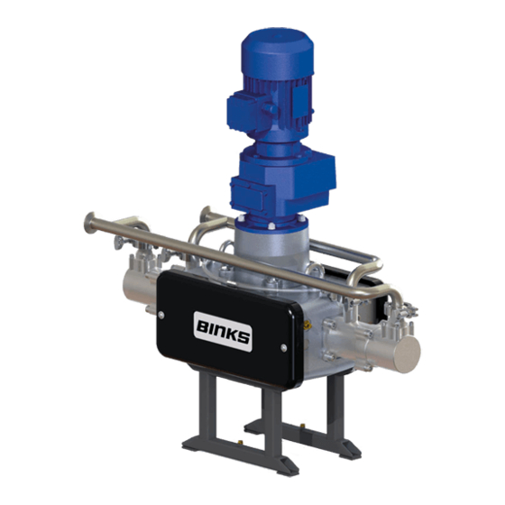
Electric Drive Pump
• 104126 (EU Model)
• 104127 (Japan Model)
IMPORTANT! DO NOT DESTROY
manual.
www.carlisleft.com
Advertisement
Table of Contents

Subscribe to Our Youtube Channel
Related Manuals for Carlisle BINKS E2-15


Summary of Contents for Carlisle BINKS E2-15
- Page 1 IMPORTANT! DO NOT DESTROY It is the Customer's responsibility to have all operators and service personnel read and understand this manual. Contact your local Carlisle Fluid Technologies representative for additional copies of this manual. READ ALL INSTRUCTIONS BEFORE OPERATING THIS PRODUCT 77-3311 R1.0...
-
Page 2: Eu Declaration Of Conformity
Providing all conditions of safe use / installation stated within the product manuals have been complied with and also installed in accordance with any applicable local codes of practice. Director of Sales (EMEA) D Smith Signed for and on behalf of Carlisle Fluid Technologies UK Ltd: 29/6/18 Bournemouth,BH11 9LH,UK 77-3311 R1.0... - Page 3 In this part sheet, the words WARNING, CAUTION and NOTE are used to emphasize important safety information as follows: WARNING CAUTION NOTE Hazards or unsafe practices which could result in Hazards or unsafe practices which could result in Important installation, operation or maintenance minor personal injury, product or property severe personal injury, death or substantial property information.
-
Page 4: Specification
SPECIFICATION Nominal pump stroke: 50mm [1.97 ins] Maximum fluid pressure: 20 bar [290 psi] Fluid inlet connection: A/ B 1'' Sanitary Fluid Output @ 20 HZ [10 cycles/min] 3.75 l/min [1.0 US gal/min] Fluid Output @ 80 HZ [40 cycles/min] 15 l/min [4.0 US gal/min] Nominal flow volume / cycle: 0.375 l [0.10 US gal]... -
Page 5: Dimensions And Mounting Details
DIMENSIONS AND MOUNTING DETAILS M6 HEX. Head screw for pump earth grounding; the Pump Frame must be wired to a suitable earth ground to ensure that there is no possibility of static build up. 77-3311 R1.0 5/36 www.carlisleft.com... -
Page 6: Installation
INSTALLATION The Pump Units are designed for location in Zone 1 Hazardous areas, ATEX Category 2. Electrical connections must be in accordance with Local Regulations for installation in Hazardous Areas. It is recommended that a Lockable Isolator is positioned in close proximity to the pump, as a convenient local Start / Stop facility. -
Page 7: Electric Motor
INSTALLATION Electric Motor The motor must be wired to provide a clockwise direction of the cam. Electric Motors for hazardous areas are specially designed to comply with official regulations concerning the risk of explosion. If improperly used, badly connected, or altered no matter how minor, their reliability could be in doubt. Standards relating to the connection and use of electrical apparatus in hazardous areas must be taken into consideration. - Page 8 INSTALLATION Attach suitable flexible hoses to the inlet and outlet connections. e.g., Suction - Ø28 I.D. [-1 to 10 bar working pressure] Outlet - Ø25 I.D. [20 bar working pressure] Ensure adequate air space around the Pump for maintenance and electric motor cooling requirements. ...
-
Page 9: System Operation
SYSTEM OPERATION Before starting:- Ensure all electrical and mechanical connections are correctly made. All required interlocks are tested and operational. Suitable material for pumping is available at the suction hose. The outlet connection is not blocked or isolated by any valves. ... -
Page 10: Parts List
PARTS LIST Pump Assembly ITEM PART NUMBER DESCRIPTION REMARKS 195480 E2-15 MECHANICAL ASSY 0.75KW ATEX MOTOR, VARIATOR & EU MODEL 194924 GEARBOX 163144 M8 HEXAGON NUT 165108 M8 SPRING WASHER 165123 Ø10 SPRING WASHER 165134 Ø10 WASHER 165947 M10 x 35 SCREW 194900 E2-15 MANIFOLD &... - Page 11 GREASE LOCTITE TORQUE MAINTENANCE ORDER (Reverse for assembly) GREASE INTERNAL (AGMD-010) 77-3311 R1.0 11/36 www.carlisleft.com...
- Page 12 PARTS LIST - PRV and Manifold Assembly ITEM PART NUMBER DESCRIPTION REMARKS 104167 PRESSURE RELIEF VALVE 192009 SANITARY CLAMP 192206 SANITARY GASKET - PTFE 194109 SANITARY ELBOW 194279 INLET MANIFOLD 194280 OUTLET MANIFOLD 194589 EXT. SANITARY ELBOW [82mm] 194590 EXT. SANITARY ELBOW [96.5mm] 77-3311 R1.0 12/36 www.carlisleft.com...
- Page 13 GREASE LOCTITE TORQUE MAINTENANCE ORDER (Reverse for assembly) GREASE INTERNAL (AGMD-010) 77-3311 R1.0 13/36 www.carlisleft.com...
-
Page 14: Mechanical Assembly
PARTS LIST Mechanical Assembly ITEM PART NUMBER DESCRIPTION REMARKS 160524 CARRIAGE SPRING 163144 M8 HEXAGON NUT 163161 M8 NYLOC NUT 163921 M6 x 25 SCREW 164471 M10 x 21 SCREW 165044 M12 SPRING WASHER 165100 M16 SPRING WASHER 165108 M8 SPRING WASHER 165123 M10 SPRING WASHER 165134... - Page 15 GREASE LOCTITE TORQUE MAINTENANCE ORDER (Reverse for assembly) GREASE INTERNAL (AGMD-010) 77-3311 R1.0 15/36 www.carlisleft.com...
- Page 16 GREASE LOCTITE TORQUE MAINTENANCE ORDER (Reverse for assembly) GREASE INTERNAL (AGMD-010) NOTE: Part No. 1 - Grease using 502375 Part No. 4 - To be tightened using tool 193120 Part No. 6 - To be tightened using tool 193119 Part No. 11 - To be pressed into housing using tool 193121 77-3311 R1.0 16/36 www.carlisleft.com...
- Page 17 PARTS LIST Bell Housing & Shaft Assemblies ITEM PART NUMBER DESCRIPTION REMARKS 162709 Ø30 x Ø42 x 7 SEAL ❸ 163960 M5 x 16 SCREW 165972 M5 x 25 SCREW 165974 BEARING LOCKNUT 192650 GREASE NIPPLE 192703 BEARING LOCKNUT 192853 BELL HOUSING MACHINING 192857 TOP BEARING CAP...
-
Page 18: Carriage Assembly
PARTS LIST Carriage Assembly ITEM PART NUMBER DESCRIPTION REMARKS 162734 Ø41 SECTION O-RING 163159 M12 PREVAILING TORQUE NUT 165542 M6 CAP HEAD SCREW 166156 Ø46 CIRCLIP 192392 Ø47 CAM FOLLOWER 192661 6mm PUSH IN ELBOW 192851 LINEAR BEARING HOUSING 192852 LINEAR BEARING CARRIAGE 192861 CARRIAGE ADAPTOR... - Page 19 GREASE LOCTITE TORQUE MAINTENANCE ORDER (Reverse for assembly) GREASE INTERNAL (AGMD-010) 77-3311 R1.0 19/36 www.carlisleft.com...
-
Page 20: Fluid Section
PARTS LIST Fluid Section ITEM PART NUMBER DESCRIPTION REMARKS 163921 M6 x 25 SCREW 163952 M6 x 20 SCREW 165087 M6 SPRING WASHER 165123 Ø10 SPRING WASHER 165947 M10 x 35 SCREW 192382 Ø25.4 BALL ❷ 192505 Ø12.42 O-RING ❶❷ 192551 1/4 BSP PLUG ❷... - Page 21 GREASE LOCTITE TORQUE MAINTENANCE ORDER (Reverse for assembly) GREASE INTERNAL (AGMD-010) 77-3311 R1.0 21/36 www.carlisleft.com...
-
Page 22: Piston Assembly
PARTS LIST Piston Assembly ITEM PART NUMBER DESCRIPTION REMARKS 160533 PISTON BALL CHECK SPRING ❶❷ 162855 Ø52.07 O-RING ❶❷ 162856 Ø41 O-RING ❶❷ 162857 Ø52.82 O-RING ❶❷ 171788 1.375 BALL ❷ 192632 SEAT ❷ 193188 INLET SPRING KEEP ❶❷ 194111 Ø70 FLUID PISTON 194113 BALL CAGE... - Page 23 PARTS LIST Piston Assembly Use a 25mm Single Hex Socket when tightening or removing ball cage from Piston. GREASE LOCTITE TORQUE MAINTENANCE ORDER (Reverse for assembly) GREASE INTERNAL (AGMD-010) 77-3311 R1.0 23/36 www.carlisleft.com...
- Page 24 PARTS LIST Shaft & Bellows Assembly ITEM PART NUMBER DESCRIPTION REMARKS 192374 RETAINING NUT 192579 KNIFED BELLOWS ❷❹ 192627 BELLOWS SPACER 192628 SHAFT SEAL ❷❹ 192864 PISTON SHAFT 502377 BELLOWS POSITIONING TOOL TOOL 502382 BELLOWS ASSEMBLY SPIGOT TOOL 77-3311 R1.0 24/36 www.carlisleft.com...
- Page 25 PARTS LIST Shaft & Bellows Assembly Screw Item No. 2 (assembly spigot) onto the piston shaft (grease spigot with AMGD-010). Using Item No. 7, push bellows over spigot until located in groove. Smear loctite 572 over nose of bellows, thread nut onto bellows ensuring the thread starts squarely.
-
Page 26: General Maintenance
Maintenance General Maintenance The working life and thus the expected life prior to replacement of parts within a Paint Pump are greatly affected by three main factors: - • Electric Motors for hazardous areas are specially designed to comply with official regulations concerning the risk of explosion. -
Page 27: Maintenance Schedule
Maintenance Maintenance schedule Inspection Operation Daily Check for any fluid leakage Check for any excessive mechanical noise Weekly Check for excessive fluid pressure pulsation While running, apply (502375) grease to cam follower bearings, 8 strokes of a 3 Monthly standard ‘cartridge’ grease gun (502373). Grease Main Shaft Bearing with 502375 grease. - Page 28 Maintenance Gearbox WARNING Wait until the unit has cooled sufficiently after stopping and isolation. Gearbox Every 1000 hours verify the good condition of oil seals and gaskets Maintenance The gearbox is supplied factory fitted with oil and is a service free unit. However if seals start to leak and oil level is reduced, both the affected seal and oil need to be replaced as a general overhaul of the unit.
-
Page 29: Electric Motors
Maintenance Motor WARNING Wait until the unit has cooled sufficiently after stopping and isolation. Electric Motors Maintenance of Ex Motors - are reported by EN 60079-17 standard, in particular:- • The electric connections must be correctly locked to avoid resistance-increases, with consequent contact overheating. -
Page 30: Fault Finding
Fault Finding Mechanics Symptom Possible Cause Remedy Gearbox Output shaft does not Drive between shafts in the gear unit Return the unit for repair and replace rotate, even though the motor is interrupted gearbox running. Gearbox Oil leaking a) Defective gasket on gear unit a) Retighten screws on gear unit cover. - Page 31 Fault Finding Fluid Section Symptom Possible Cause Remedy a) Air entering the suction a) Check o-rings and hose hose/manifold connections b) Worn piston seals b) Replace piston seals. Pump will not ‘Prime’ c) Ball checks not seating correctly. c) Inspect, clean and/or replace balls and seats.
- Page 32 Testing and Lubricating Testing and Lubricating after major overhaul WARNING Testing and Lubricating - Qualified personnel only 1. Connect pump to paint system. 2. Connect electric motor to a suitable electrical supply. 3. Fit the gearbox vent plug. 4. Turn on paint system and set back pressure regulator to zero. 5.
- Page 33 E2-15 Pumps - Spare Parts List KIT No. Part No. Description Remarks 192850 Constant Velocity Cam 192392 Cam Follower Bearing Kit 194242 Ø70 Piston 192871 Linear Bearing 192579 Bellows (fluid section) 250790 ** Fluid section seal kit 250736 ** Fluid Section overhaul kit ...
- Page 34 ACCESSORIES PART NUMBER DESCRIPTION REMARKS 192800 Smart Card V3.0 194495 Sensor Manifold 192547 [4-20 mA / 0-25 bar] Pressure Sensor Pressure Feedback 502373 Grease Gun for Cam Follower (& Main Bearings) Collet Connector 502375 Grease for Cam Follower (& Main Bearings) 502912 1 Litre bottle of Variator oil 192206...
- Page 35 ACCESSORIES PART NUMBER DESCRIPTION REMARKS 192450 M8 Torx Security Screwdriver for Cover FOC with a New Pump 193119 Top Bearing Locknut Tool 193120 Bottom Bearing Locknut Tool 193121 Top Bearing Press Tool 193122 Bottom Bearing Press Tool 502377 Bellows Assembly Tool 502382 Bellows Assembly Spigot 502813...
- Page 36 WARRANTY POLICY This product is covered by Carlisle Fluid Technologies’ materials and workmanship limited warranty. The use of any parts or accessories, from a source other than Carlisle Fluid Technologies, will void all warranties. Failure to reasonably follow any maintenance guidance provided, may invalidate any warranty.
Need help?
Do you have a question about the BINKS E2-15 and is the answer not in the manual?
Questions and answers