Table of Contents
Advertisement
Quick Links
Service Manual
EN
It is the Customer's responsibility to have all operators and service personnel read and understand this
Contact your local Carlisle Fluid Technologies representative for additional copies of this manual.
READ ALL INSTRUCTIONS BEFORE OPERATING THIS PRODUCT
77-3337 R2.1 (11/2023)
• 104274 - EU Model
• 104272 - Japan Model
• 104271 - USA Model
• 104282 - China Model
IMPORTANT! DO NOT DESTROY
manual.
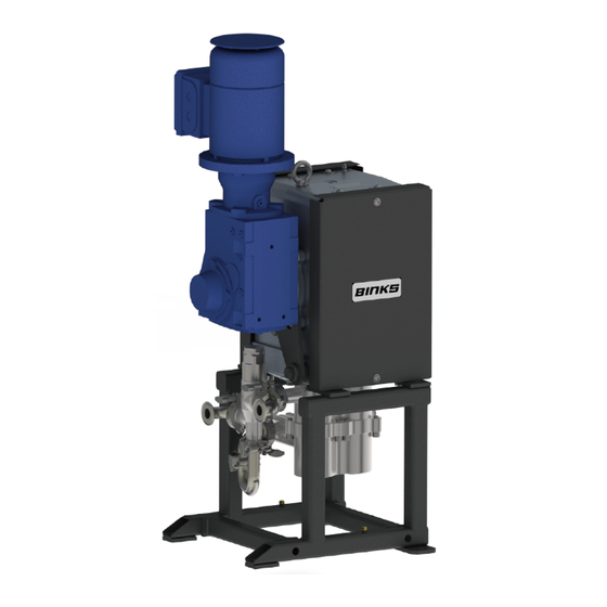
EV2-15
Smart Pump
www.carlisleft.com
Advertisement
Table of Contents

Related Manuals for Carlisle BINKS EV2-15


Summary of Contents for Carlisle BINKS EV2-15
- Page 1 It is the Customer's responsibility to have all operators and service personnel read and understand this manual. Contact your local Carlisle Fluid Technologies representative for additional copies of this manual. READ ALL INSTRUCTIONS BEFORE OPERATING THIS PRODUCT 77-3337 R2.1 (11/2023)
-
Page 2: Eu Declaration Of Conformity
II 2 GD ck T4 (Gearbox) Notified body details and role: Element Materials Technology (2812) Lodging of Technical file This Declaration of conformity / incorporation is Carlisle Fluid Technologies UK Ltd, Ringwood Road, issued under the sole responsibility of the Bournemouth, BH11 9LH. UK manufacturer: Representative authorised to compile the technical Sales and Marketing Director. - Page 3 II 2 GD ck T4 (Gearbox) Approved body details and role: Element Materials Technology (0891) Lodging of Technical file This Declaration of conformity/incorporation is Carlisle Fluid Technologies UK Ltd, issued under the sole responsibility of the Ringwood Road, manufacturer: Bournemouth, BH11 9LH. UK ...
- Page 4 In this part sheet, the words WARNING, CAUTION and NOTE are used to emphasize important safety information as follows: WARNING CAUTION NOTE Hazards or unsafe practices which could result in Hazards or unsafe practices which could result in Important installation, operation or maintenance minor personal injury, product or property severe personal injury, death or substantial property information.
-
Page 5: Specification
SPECIFICATION Nominal pump stroke: 50mm [1.97 ins] EV2-15 Maximum fluid pressure:* 20bar [290psi]* EV2-15 Nominal flow volume / cycle: 0.375 l/m [0.10 US gal/m] Fluid Output @ 20 HZ [10 cycles/min] 3.75 l/m [1.0 US gal/m] Fluid Output @ 80 HZ [40 cycles/min] 15 l/m [4.0 US gal/m] Fluid inlet connection: 1'' Sanitary... -
Page 6: Dimensions And Mounting Details
DIMENSIONS AND MOUNTING DETAILS M6 HEX. Head screw for pump earth grounding; the Pump Frame must be wired to a suitable earth ground to ensure that there is no possibility of static build up. SECTION A-A 77-3337 R2.1 www.carlisleft.com... -
Page 7: Installation
INSTALLATION The Pump Units are designed for location in Zone 1 Hazardous areas, ATEX Category 2. Electrical connections must be in accordance with Local Regulations for installation in Hazardous Areas. It is recommended that a Local Control Box is positioned in close proximity to the pump, as a convenient local Start / Stop facility and Junction box. -
Page 8: Electric Motor
INSTALLATION Electric Motor The motor must be wired to provide a clockwise direction of the cam. Electric Motors for hazardous areas are specially designed to comply with official regulations concerning the risk of explosion. If improperly used, badly connected, or altered no matter how minor, their reliability could be in doubt. Standards relating to the connection and use of electrical apparatus in hazardous areas must be taken into consideration. - Page 9 INSTALLATION Attach suitable flexible hoses to the inlet and outlet connections. e.g., Suction - Ø28 I.D. [-1 to 10 bar working pressure] Outlet - Ø25 I.D. [20 bar working pressure] Ensure adequate air space around the Pump for maintenance and electric motor cooling requirements. ...
-
Page 10: System Operation
SYSTEM OPERATION Before starting:- Ensure all electrical and mechanical connections are correctly made. All required interlocks are tested and operational. Suitable material for pumping is available at the suction hose. The outlet connection is not blocked or isolated by any valves. ... - Page 11 PARTS LIST – Pump Assembly ITEM PART NUMBER DESCRIPTION 104270 EV2-15 Pump Assembly 195836 PRV & EV2-15 MANIFOLD KIT 195754 TORQUE ARM 177152 M18 x 50 SCREW 195761 WASHER 177151 M8 x 16 SCREW 7 ** 195829 ATEX GEARBOX & MOTOR - EU Model 172609 7 ** ATEX/CCC GEARBOX &...
- Page 12 PARTS LIST – Pump Assembly ITEM PART NUMBER DESCRIPTION 104269 DRIVE UNIT 164838 RIVET 195840 NAMEPLATE 195755 TORQUE ARM PIN 162895 O-RING 104268 FLUID SECTION 195834 COVER C/W CAP FIXINGS 77-3337 R2.1 www.carlisleft.com...
- Page 13 GREASE LOCTITE TORQUE MAINTENANCE ORDER (Reverse for assembly) GREASE INTERNAL (AGMD-010) 77-3337 R2.1 www.carlisleft.com...
- Page 14 PARTS LIST – Drive Unit ITEM PART NUMBER DESCRIPTION REMARKS 160524 CARRIAGE SPRING 163161 M8 AEROTIGHT NUT 163921 M6 x 25 SCREW 160544 M12 SPRING WASHER 165108 M8 SPRING WASHER 165123 M10 SPRING WASHER 165351 M12 x 50 SCREW 165659 M8 x 12 GRUB SCREW 165661...
- Page 15 GREASE LOCTITE TORQUE MAINTENANCE ORDER (Reverse for assembly) GREASE INTERNAL (AGMD-010) 77-3337 R2.1 www.carlisleft.com...
- Page 16 PARTS LIST – CAM SHAFT ASSY ITEM PART NUMBER DESCRIPTION REMARKS 195744 EV2-15 DRIVE PLATE - MACHINED 195828 BALL BEARING 195756 TOP BEARING CAP 192859 BOTTOM BEARING HOUSING 162709 SEAL 165972 M5 X25 CAP HEAD SCREW 165974 BEARING LOCKNUT 163951 M6 X16 CAP HEAD SCREW (ST ST) 195831...
- Page 17 GREASE LOCTITE TORQUE MAINTENANCE ORDER (Reverse for assembly) GREASE INTERNAL (AGMD-010) 77-3337 R2.1 www.carlisleft.com...
- Page 18 PARTS LIST – Shaft Assembly ITEM PART NUMBER DESCRIPTION 192850 CONSTANT VELOCITY CAM 195753 DRIVE SHAFT 195752 MIDDLE SHAFT 192856 BASE SHAFT 165558 M8 x 50 CAP HEAD SCREW (PLATED) Position first cam 180 degrees out of phase with second cam. Ensure both cam faces marked "TOP"...
- Page 19 PROCEDURE – Shaft Assembly Assembly Tool CAM Radial pitch offset Hold assembly tool (502955) in a vice (flats provided) and install middle shaft. Place CAM onto middle shaft (with 'TOP' engraving facing down towards the assembly tool). Place the base shaft on top of the CAM, align the holes and screw in the M8 x 50 cap head screws using Loctite 243 and tighten to 30Nm.
- Page 20 PARTS LIST – Top Carriage Assembly ITEM PART NUMBER DESCRIPTION REMARKS 192392 Ø47 CAM FOLLOWER 192852 LINEAR BEARING CARRIAGE 192851 LINEAR BEARING HOUSING 195764 CAM FOLLOWER PIN 192871 Ø25 LINEAR BEARING 193112 10 x 12 x 14mm LINEAR BEARING 162734 Ø41 x 1.78 SECTION O-RING 194820...
- Page 21 GREASE LOCTITE TORQUE MAINTENANCE ORDER (Reverse for assembly) GREASE INTERNAL (AGMD-010) 77-3337 R2.1 www.carlisleft.com...
- Page 22 PARTS LIST – Bottom Carriage Assembly ITEM PART NUMBER DESCRIPTION REMARKS 192392 Ø47 CAM FOLLOWER 192852 LINEAR BEARING CARRIAGE 192851 LINEAR BEARING HOUSING 195764 CAM FOLLOWER PIN 192861 CARRIAGE ADAPTOR 165542 M6 x 12 SOCKET HEAD CAP SCREW 192871 Ø25 LINEAR BEARING 193112...
- Page 23 GREASE LOCTITE TORQUE MAINTENANCE ORDER (Reverse for assembly) GREASE INTERNAL (AGMD-010) 77-3337 R2.1 www.carlisleft.com...
-
Page 24: Parts List - Fluid Section
PARTS LIST – Fluid Section ITEM PART NUMBER DESCRIPTION REMARKS 195745 INLET CYLINDER 195746 OUTLET CYLINDER 195842 Ø70 PISTON ASSEMBLY 194176 SHAFT/BELLOWS ASSY 162844 PISTON SEAL 192551 1/4" BSP HEXAGON PLUG 192505 Ø12.42 x 1.78 O-RING 163921 M6 x 25 CAP HEAD SCREW (ST ST) 165123 M10 SPRING WASHER (ST ST) 165947... - Page 25 77-3337 R2.1 www.carlisleft.com...
- Page 26 PARTS LIST – Piston Assembly ITEM PART NUMBER DESCRIPTION REMARKS 160540 BALL CHECK SPRING 162855 Ø52.07x 2.62 O-RING 162856 Ø41.0 x 1.78 O-RING 162857 Ø52.82 x 2.62 O-RING 171788 ST ST BALL 192632 PISTON INLET SEAT ...
- Page 27 Use a 30mm Single Hex Socket when tightening or removing ball cage from Piston. GREASE LOCTITE TORQUE MAINTENANCE ORDER (Reverse for assembly) GREASE INTERNAL (AGMD-010) 77-3337 R2.1 www.carlisleft.com...
- Page 28 PARTS LIST – Shaft & Bellows Assembly ITEM PART NUMBER DESCRIPTION REMARKS 192374 RETAINING NUT 192579 KNIFED BELLOWS 192627 RETAINING NUT 192628 SHAFT SEAL 192864 PISTON SHAFT 502377 BELLOWS POSITIONING TOOL TOOL 502382 BELLOWS ASSEMBLY SPIGOT TOOL Screw Item No. 7 (assembly spigot) onto the piston shaft (grease spigot with AMGD-010).
- Page 29 PARTS LIST – PRV and Manifold Assembly ITEM PART NUMBER DESCRIPTION 104167 1'' SMART PUMP PRV 192009 1/1.5'' SANITARY CLAMP 192206 1/1.5'' SANITARY GASKET - PTFE 194109 1'' SANITARY ELBOW 195751 1'' OUTLET MANIFOLD * See separate Pressure Relief Valve service manual for further details (77-3243). GREASE LOCTITE TORQUE...
-
Page 30: General Maintenance
MAINTENANCE General Maintenance The working life and thus the expected life prior to replacement of parts within a Paint Pump are greatly affected by three main factors: - Abrasiveness of Fluid Pumped Pump Duty Cycle Fluid Pressure Output Requirement ... -
Page 31: Maintenance Schedule
MAINTENANCE Maintenance schedule Inspection Operation Daily Check for any fluid leakage Check for any excessive mechanical noise Check for excessive fluid pressure pulsation Weekly Check gearbox temperature, (has over temperature been activated?) While running, apply (502375) grease to cam follower bearings, 8 strokes of a standard ‘cartridge’... - Page 32 MAINTENANCE – Gearbox WARNING Wait until the unit has cooled sufficiently after stopping and isolation. Gearbox Every 2000 hours verify the good condition of oil seals and gaskets Check oil level within gearbox Maintenance However, if seals start to leak and oil level is reduced, both the affected seal and oil need to be replaced as a general overhaul of the unit.
-
Page 33: Electric Motors
MAINTENANCE – Motor WARNING Wait until the unit has cooled sufficiently after stopping and isolation. Electric Motors Maintenance of Ex Motors - are reported by EN 60079-17 standard, in particular:- • The electric connections must be correctly locked to avoid resistance-increases, with consequent contact overheating. -
Page 34: Fault Finding
FAULT FINDING Mechanics Symptom Possible Cause Remedy Gearbox Output shaft does not Drive between shafts in the gear unit Return the unit for repair and rotate, even though the motor is interrupted replace gearbox running. Gearbox Oil leaking a) Defective gasket on gear unit a) Retighten screws on gear unit cover. -
Page 35: Fluid Section
FAULT FINDING Fluid Section Symptom Possible Cause Remedy entering suction Check o-rings hose hose/manifold connections b) Worn piston seals b) Replace piston seals. Pump will not ‘Prime’ c) Ball checks not seating correctly. c) Inspect, clean and/or replace balls and seats. a) No power a) Check electrical supply b) Inverter Unit or safety interlocks... - Page 36 TESTING AND LUBRICATION Testing and Lubricating after major overhaul WARNING Testing and Lubricating - Qualified personnel only Connect pump to paint system. Connect electric motor to a suitable electrical supply. Fit the gearbox vent plug, or remove rubber bung. Turn on paint system and set back pressure regulator to zero. Turn the pump on at the local isolation mounted switch.
-
Page 37: Spare Parts List
SPARE PARTS LIST Recommended Replacement Spare Parts and Kits for EV2-15 Pumps KIT No. PART No. DESCRIPTION 192850 CONSTANT VELOCITY CAM 192392 1 x Ø47 CAM FOLLOWER 194111 FLUID PISTON 192871 1 x LINEAR BEARING 192579 1 x KNIFED BELLOWS ... - Page 38 ACCESSORIES PART No. DESCRIPTION REMARKS 192800 Smart Card V3.0 502501 BPR Control Box 502483 Electrical Panel for Single Pump Operation Inc. Smart Card 194495 Sensor Manifold [4-20 mA / 0-25 bar] 192547 Pressure Feedback Pressure Sensor 502373 Grease Gun for Cam Follower (& Main Bearings) Collet Connector 502375 Grease for Cam Follower (&...
- Page 39 ACCESSORIES PART No. DESCRIPTION REMARKS 192450 M8 Torx Security Screwdriver for Cover FOC with a New Pump 193120 Bottom Bearing Locknut Tool 193122 Bottom Bearing Press Tool 502954 Top Bearing Press Tool 502955 CV Cam & Shaft Assembly Tool 502377 Bellows Assembly Tool 502382 Bellows Assembly Spigot...
- Page 40 Gearbox Long Term Storage Storage or inactivity for over nine months Without taking additional storage measures, internal components such as bearings and gears will start to rust due to a lack of oil circulation and / or condensation. This will result in accelerated wear during operation.
- Page 41 NOTES 77-3337 R2.1 www.carlisleft.com...
- Page 42 NOTES 77-3337 R2.1 www.carlisleft.com...
- Page 43 NOTES 77-3337 R2.1 www.carlisleft.com...
- Page 44 WARRANTY POLICY This product is covered by Carlisle Fluid Technologies’ materials and workmanship limited warranty. The use of any parts or accessories, from a source other than Carlisle Fluid Technologies, will void all warranties. Failure to reasonably follow any maintenance guidance provided, may invalidate any warranty.
Need help?
Do you have a question about the BINKS EV2-15 and is the answer not in the manual?
Questions and answers