Table of Contents
Advertisement
Quick Links
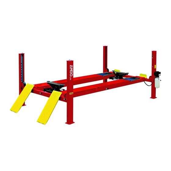
Model:PRO-12SX,PRO-12ASX
Cargo Claims
If there is any missing or damaged
product during transportation, the
buyer must notate on the shipping
paperwork or refuse the shipment.
NOTATE ALL DAMAGE OR REFUSE
FOUR POST LIFT
△
!
Read the entire contents of this manual before
using this product. Failure to follow instructions
and safety precautions could result in serious
injury or even death. Make sure all other
operators also read this manual. Keep this
manual near the machine so that it can be seen
by all users. By proceeding with installation and
operation, you agree that you are fully
understand the contents of this manual and take
full responsibility for the use of the product.
DANGER
Advertisement
Table of Contents

Related Manuals for AMGO Hydraulics PRO-12SX


Summary of Contents for AMGO Hydraulics PRO-12SX
- Page 1 FOUR POST LIFT Model:PRO-12SX,PRO-12ASX △ DANGER Read the entire contents of this manual before using this product. Failure to follow instructions and safety precautions could result in serious injury or even death. Make sure all other Cargo Claims operators also read this manual. Keep this...
-
Page 2: Table Of Contents
CONTENTS PROFILE ..........................1 IMPORTANT SAFETY INSTRUCTIONS ................ 3 I. PRODUCT FEATURES AND SPECIFICATIONS ............ 5 II. INSTALLATION REQUIREMENT ................6 III. INSTALLATION STEPS ..................... 8 IV. EXPLODED VIEW ...................... 28 V. TEST RUN ........................35 VI. OPERATION INSTRUCTIONS ................36 VII. -
Page 3: Profile
PROFILE The four post lift is a commonly used vehicle repair and maintenance tool that uses a hydraulic system that can lift the car up to a certain height so that the vehicle can be placed in a suitable position for inspection and repair. Car lifts can be divided into pneumatic and electric, which have the characteristics of safe and reliable, simple structure and quick installation. -
Page 4: Safety Warning Label
SAFETY WARNING LABEL... -
Page 5: Important Safety Instructions
IMPORTANT SAFETY INSTRUCTIONS In order to properly maintain your product and ensure operator safety, it is the responsibility of the product owner to read and follow these instructions! 1. Ensure product installation complies with all applicable local regulations and rules, such as Occupational Safety and Health Administration regulations and electrical codes. - Page 6 16. Maintain with care. Keep the machine clean for better and safer operation. Perform proper lubrication and maintenance procedures according to the manual. Keep handles or buttons clean, dry, and free of oil. 17. Stay alert. Use common sense to observe what you are doing and stay alert. 18.
-
Page 7: Product Features And Specifications
● Manual hydraulic power system,cable-drived. ● Non-skid diamond platforms. ● Adjustable platform and adjustable safety lock ladders. ● Optional Jack : With hand pump or pneumatic pump. ● Optional Turnplates: (Only for PRO-12ASX) PRO-12SX PRO-12ASX Fig.1 Fig.2 MODEL PRO-1 2S X( ASX) SPECIFICATIONS Overall Max. -
Page 8: Installation Requirement
II. INSTALLATION REQUIREMENT TOOLS REQUIRED Rotary Hammer Drill(Φ3/4) Carpenter’s Chalk Screw Sets Hammer Level Bar Tape Measure(295-1/4") Adjustable Spanner (12") Pliers Wrench set(10#,12#,13#,14#,17#, Lock wrench 19#,24#,30#) Socket Head Wrench (3 Ratchet Spanner With Socket (28 ... - Page 9 B. Equipment storage and installation requirements. 1.Store the equipment in a dry, non-moldy, non-flammable environment. 2.The lift is generally approved for indoor installation and use. If need outdoor installation, the optional motor protect cover is required. 3.When installing the device, take safety precautions according to the instructions to avoid device damage.
-
Page 10: Installation Steps
E. AIR SUPPLY Air pressure requirement: 0.8Mpa, air line size ¢8×¢6 and ¢6×¢4. F. POWER SUPPLY 1. You are required to use a licensed and qualified electrician for the installation process. 2. The power supply capacity must be more than 2.0HP, with a cord larger than 12AWG, and must be properly grounded. - Page 11 4. Loose the screws of the upper package stand, take off the off-side platform, take out the parts inside the power side platform, then remove the package stand. Move aside all the parts to the installation position and check the parts according to parts list (See Fig. 9, Fig.10). PRO-12SX Fig.9...
- Page 12 PRO-12ASX Fig.10 6. Check the parts of parts box according to the parts box lift . (See Fig. 11). Fig.11...
- Page 13 7. Check the parts of the parts bag according to the parts bag list (See Fig. 12). PRO-12SX Parts Bag(1) PRO-12ASX Parts Bag(1) Parts Bag(2) Fig.12...
- Page 14 Use a carpenter’s chalk line to establish installation layout (see Fig.13) . Place the posts according to the installation dimension. Note: Reserve space front and behind the installation site. Car in Use a carpenter’s chalk line to establish installation layout Fig.13 Model PRO-12SX 196-3/4” 132-1/8” 237” PRO-12ASX...
- Page 15 D. Install cross beams (See Fig.15 & 16). Window towards inward Fig.14 Fig.15...
- Page 16 E. Fix anchor bolts. 1. Prepare the anchor bolts (See Fig. 16). Lock washer Flat Washer Fig.16 2. Using the prescribed rotary hammer drill, and drill all the anchor holes and install the anchor bolts. Do not tighten the anchor bolts (See Fig. 17). Note: Anchor bolts driven into the ground at least 4”.
- Page 17 2. Install safety ladders (See Fig. 19). This height for four threaded rod of safety ladders should be the same. Safety ladder pass through the hole of the top plate, then tighten the two nuts Fig.19 G. Put the cross beams at the same height (See Fig. 20). All 4 safety devices on crossbeams should be locked at...
- Page 18 H. Install power-side platform. 1. Put the power-side platform upon the cross beams by forklift or manual, offset the cross beams to the outside till the pulleys of both platforms can set up into the cross beam (See Fig.21,22), Install the power-side platform and screw up the bolts (See Fig.23) .
- Page 19 I. Assembly offside platform and slider block, (See Fig. 24) check the plumb ness of columns with level, adjusting with the shims if not, and then tighten the anchor bolts (See Fig. 25). Check the plumbness of columns with level bar, adjust with the shims if necessary.
- Page 20 J. Illustration for cable installation (See Fig. 26). 1. Pass through the cables from the platform to the columns according to the number of the cables. Cables Installation Fig.26 ○ ○ ○ ○ Cable Length ” ” ” ” 146-5/8 398-5/8 209-5/8 335-3/8...
- Page 21 2. The cable pass through the cross beam to top plate of columns and be screwed with cable nuts (See Fig. 27, 28), then install the cable limit pin. (See Fig. 29) Pass the cable through top plate Pass the cable through between the and tighten with cable nut.
- Page 22 7. Illustration for platform cables (See Fig. 30, 31, 32). ○ Cable ○ Cable ○ Cable ○ Cable ○ Cable ○ Cable Fig.30 ○ Cable ○ ○ Cable Cable ○ Cable ○ Cable ○ Cable Fig.31 ○ Cable ○ Cable Socket Bolt M10*120 Fig.32...
- Page 23 K. Install oil-water separator, manual control air valve and power unit (See Fig. 33) Air Direction of Oil-water Separator The side marking “ P” on the air valve is Air Input. direction Air Flow Direction Fig.33...
- Page 24 L. Install hydraulic system. Note: Oil hoses and oil return pipe connected to oil cylinder must be passed above the cable and cylinder inlet port must swing upward to avoid the oil hose and oil return pipe scratched by cable. Oil and air lines through the clamp...
- Page 25 M. Install air-line system 1. Connect the front and rear cross beam with φ6*φ4 black air line (the actual length of air line can be cut by user) (See Fig.38) 2. Use scissors to cut off the φ6*φ4 black air line from the middle between two retainers, and then connect to the T fitting.
- Page 26 8. Connecting Oil-water separator and Manual control air valve using air line (See Fig. 41) . Oil-water separator Connect Oil-water separator and Manual control air valve using black air line 8*6 Manual control air valve Black air line 8*6 Fig.41 5.
- Page 27 N. Install Electrical System Connect the power source on the data plate of Motor. Note: For the safety of operators, the power wiring must contact the floor well. Single phase motor (See Fig. 43) Connect the two power supply wire (fire wire L1 and L3) to terminals of AC contactor marked L1, L3 respectively.
- Page 28 P. Install drive-in ramp, tire stop plate, platform lock plates,Limit rod (See Fig. 45). 35-1 35-2 35-3 35-4 Exploded view of Drive-in ramp assy. Install Drive-in Ramp Fig.45 Item Part# Description 1104013001A Drive-in Ramp (PRO-12SX) 35-1 1104223004A Drive-in Ramp (PRO-12ASX) 35-2 11610667 Roller 35-3 11620043 35-4 10209010 Clip Ring φ10...
- Page 29 Q. Install stop plate, turnplate adjusting block, limit rod and lock plate.(See Fig. 46) After install the turnplate cover and adjustable blocks, install the limit rod. Install stop Plate Fig.46 Install the lock plate to the off side platform with M8*20 hex bolt and nylok nut.
-
Page 30: Exploded View
IV. EXPLODED VIEW Model:PRO-12SX Fig.47... - Page 31 Model:PRO-12ASX When installing the turntables, both sides are required a 35mm-height turntable block. Fig.48...
- Page 32 PARTS LIST FOR PRO-12SX, PRO-12ASX Description Item Part# PRO-12SX PRO-12ASX 11420011A Power-side Column 11420002 Offside Column 1104062001C Cross Beam Assy. 10209059 Anchor Bolt 3/4*5-1/2 11410022 Safety Ladder 10420175A Hex Nut M20 11490001-01 Power-side Platform 11496001-01 Power-side Platform 11420022A-01 Pulley Pin...
- Page 33 Description Item Part# PRO-12SX PRO-12ASX 1061K050 Hex Bolt M8*30 1104013001C Drive-in Ramp assy. 1104223004C 10209066 Hex Nut M16 10420156 Protecting Ring 10420045 Flat Washer φ6 11420004 Pin for Drive- in Ramp 10420005 Set screw M5*8 10420502 Parts B ox 10430501...
- Page 34 Description Item Part# PRO-12SX PRO-12ASX Air line 1/4"×3/16" 10420131C Air line 5/16"×1/4"×18 1/8" 10420167A 1040101 Turnplate(Optional) 11430004 Turnplate Cover 11520037 11480028 Slip plate 10420157 Steel ball set Turnplate Block 19"×3"×2" 11480033 Turnplate Block 19"×1 3/8"×1 3/8" 11480045 Turnplate Block 19"×5 9/16"×2"...
- Page 35 Item Part# Description Item Part# Description 11480023 Cross Beam 3-14 10420042 Slider block 10420051B Protective cover 3-15 10209033 Flat Washer φ8 Socket Bolt M8*20 Round Head Bolt 10209009 3-16 10420043 M6*8 11420044 Limit Block 11480114 Safety block 2(left) 3-17 10420138 Socket Bolt M6*16 11480115 Safety block 2(Right)
- Page 36 4.3 Power Unit Explosive View Guard Coil Oil Return Port Relief Valve Release Valve Throttle Valve Check Valve Oil Outlet Port Release Valve Handle Fig.51 4.3.1 Adjust the lower speed Adjust the lower speed of the lift according to demand: Turn the Throttle Valve in clockwise direction to decrease the lower speed, or increase the speed in counterclockwise direction.
-
Page 37: Test Run
V. TEST RUN 1. Fill the reservoir with approximately 11 L Hydraulic Oil (Note: In consideration of Power Unit’s durability,please use Hydraulic Oil 46#). Press button UP, the Cables will be strained. Check whether the Cables match the Pulley. Make sure the Cables are not across. 3. -
Page 38: Operation Instructions
VI. OPERATION INSTRUCTIONS To lift vehicle Keep clean of environment near the lift; Ensure the air source switch is activated, drive vehicle to the platform and apply the brake. Turn on the power and press the button UP, raise the lift to the working position; Note: make sure the vehicle is steady when the lift is raised. -
Page 39: Maintenance Schedule
VII. MAINTENANCE SCHEDULE Monthly: Re-torque the anchor bolts to 150Nm; Lubricate cable with lubricant; Check all cable connection, bolts and pins to insure proper mounting; Make a visual inspection of all hydraulic hoses/lines for possible wear or leakage; Lubricate all Rollers, Safety devices with 90wt. gear oil or equivalent. Note: All anchor bolts should take full torque. -
Page 40: Trouble Shooting
VIII. TROUBLE SHOOTING TROUBLE CAUSE REMEDY 1. Start Button does not work 1. Replace start button 2. Wiring connections are not in good condition 2. Repair all wiring connections Motor does 3. Motor burned out 3.Repair or replace motor not run 4. -
Page 41: Car Lift Safety Tips
IX. CAR LIFT SAFETY TIPS Put this safety tips in a place where you can always alert the operator. Please reference to the lift manufacturer’s manual for specific information about the lift. Check the lift daily. If the machine breaks down or has damaged parts, do not operate, and use original equipment parts to repair. - Page 42 72247503 2024/6 40 40...
Need help?
Do you have a question about the PRO-12SX and is the answer not in the manual?
Questions and answers