Table of Contents
Advertisement
Quick Links
Advertisement
Table of Contents

Related Manuals for AMGO Hydraulics BP-12


Summary of Contents for AMGO Hydraulics BP-12
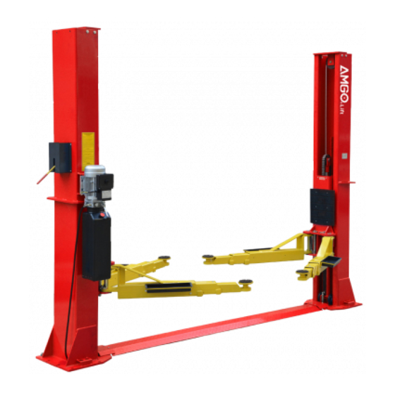
- Page 1 TWO POST LIFT Model: BP-12...
-
Page 2: Table Of Contents
CONTENTS Product Features and Specifications ............1 Installation Requirement ................3 Steps of Installation ………………………………………………………..…………....4 Exploded View ..................20 Test Run .....................27 Operation Instruction ................29 Maintenance ..................29 Trouble Shooting .................31 Lift Disposal ..................31... -
Page 3: Product Features And Specifications
· Self-lubricating UHMW Polyethylene sliders and bronze bush. · Single-point safety release, and dual safety design. ·¢9.5 mm cable using for the lift make it more safety and more reliable. MODEL BP-12 SPECIFICATIONS Lifting Lifting Overall... - Page 4 Arm Swings View 36-7/8” 104-1/2”~109-7/8” 71-5/8” Fig.2...
-
Page 5: Installation Requirement
II. INSTALLATION REQUIREMENT A. TOOLS REQUIRED Rotary Hammer Drill (Φ19) Carpenter’s Chalk Hammer Screw Sets Level Bar Tape Measure (7.5m) English Spanner (12") Pliers Ratchet Spanner With Socket (28 Socket Head Wrench (6 ... - Page 6 B. Equipment storage and installation requirements. The equipment should be stored or installed in a shady, normal temperature, ventilated and dry place. C.The equipment should be unload and transfer by forklift. Fig. 4 D. SPECIFICATIONS OF CONCRETE (See Fig. 5) Specifications of concrete must be adhered to the specification as following.
-
Page 7: Steps Of Installation
III. STEPS OF INSTALLATION A. Location of Installation Check and insure the installation location (concrete, layout, space size etc.) is suitable for lift installation. B. Use a carpenter’s chalk line to establish installation layout of baseplate (See Fig. 6). Chalk a line Fig. - Page 8 3.Take out the parts upper and inside the column, move them beside the installation site. See Fig.9 Fig. 9 Label 4. Loose the screws of the upper package stand, take off the upper column and remove the package stand. 5. Move aside the parts and check the parts according to the shipment parts list (See Fig.
- Page 9 D. Lay down two columns on the installation site in parallel, position the power-side column according to the actual installation site. Usually, it is suggested to install Power side column on the front-right side from which vehicles are driven to the lift. Then install the top plate (See Fig.
- Page 10 E. Position columns and install anchor bolts (See Fig. 14) Check the columns plumbness with level bar, and adjusting with the shims if the columns are not vertical. Anchor bolts should not be tightened. Note: Lifts are designed to two level width, install according to customer’s needs 118 1/8”...
- Page 11 2. Using the prescribed rotary hammer drill, drill all the anchor holes and install the anchor bolts. Then tighten the anchor bolts (See Fig. 16). Note: Torque of Anchors is 150N.m. Minimum embedment of Anchors is 4-3/8”. Drilling Bolting Tighten Fig.
- Page 12 H. Lift the carriages up by hand and make them be locked at the same level (See Fig.19) Safety block locked at the same level Fig.19...
- Page 13 I. Connecting cables (See Fig. 20) 1. Select the width of the foundation according to step E (Fig.14) and select the width of the foundation size 150-3/4” to install the cable (see Fig.20) Note: Cable pass through from one carriage to another must be passed through the hole of the bottom steel plate of carriages steel plate of carriages...
- Page 14 2.Select the width of the foundation according to step E (Fig.14) and select the width of the foundation size 145-3/8” to install the cable.(Fig.21&Fig22) 2.1. Cable go through from bottom to the top, tighten the two cable nuts when it pass through the opening of the carriage.
- Page 15 2.2 Foundation size 145 3/8” cable installation diagram. Fig. 22...
- Page 16 J. Install safety cable, see Fig.23 1. Assemble safety cable from offside safety assy. NOTE: 2. Pay attention to the connecting direction of safety cable. 1.Insert safety cable from offside safety lock 2.Insert safety cable from offside safety lock to power-side safety lock according to the arrow direction 3.Tighten the nuts after...
- Page 17 K. Install power unit and oil hose (See Fig. 24) A View Fig.24 Width in 118 1/8”, use L= 54 7/8”oil hose Width in 123 1/2”, use L= 59 7/8”oil hose.
- Page 18 Install protect cover (see Fig.25) Note: Install cable protect cover or cable protect cover assy with connecting protect cover according to the foundation width of step 5 Install the cable protect cover assy with protect cover plate, choosing columns width in 123 1/2”...
- Page 19 M. Install lifting arms 1. After Installing the lifting arms (See Fig. 26) Lowing the carriages down to the lowest position, then use the 8# wrench to loosen the nut of the fixed gear (See Fig. 27). adjust the gear according to the arrow direction(see Fig.28), tighten the screws until the gear and rack match in good condition (see Fig.29) Use wrench to loosen the Socket...
- Page 20 Install lifting arm guardrails Fig. 29 M. Tighten all the hydraulic fittings, and fill the reservoir with hydraulic oil Note: In consideration of Hydraulic Power Unit’s durability and keep the equipment running in the perfect condition, please use Hydraulic Oil 46#. O.
- Page 21 1.2 Wire connection steps (see Fig.31) 1. Connecting the two power supply wires (active wire L and neutral wire N) to terminals of AC contactor marked L1, L2 respectively. 2. Switch ( connect with terminals of AC contactor marked L1. Terminals A1 connected with terminals of switch 4# Connect power supply wire...
-
Page 22: Exploded View
IV. EXPLODED VIEW Model BP-12 Car in direction Fig. 33... - Page 23 Model BP-12 PARTS LIST FOR Item Part# Description Item Part# Description Stackable Protect Cover 11207001 11209052B Adapter(2.5") Stackable Cable Protect 11207002 11209053B Adapter(5") Cover Cable Protect Tool Tray(short) 11207003 10206156 Cover Assy Top Pulley Toe guard (short) 11217019 11206154 Bronze Bush For...
- Page 24 Arm Lock bar (left) Rubber ring φ8*φ20*3 11217046B 10209004 Rack Handle Hex bolt M8*25 11209153 10209003 ring-pull 90° Fitting Connector BL646 10201010A 10207024 3/8NPT(M)*1/4NPT(M) Extended Straight Chain BL646 10207015 10207035 fitting L=86mm 90° Fitting Hex Bolt M10*15 10209038 10420097 1/4NPT(M)*1/4JIC(M) Oil hose 1/4*1520mm Top Plate Assy 11207016...
- Page 25 4.2 Chain pulley seat assy. (11207681) exploded view : Fig.35 Item Part# Description 81400335 Socket bolt M5*10 11207006 Pin for chain pulley Bronze bush for chain pulley 10420132A φ41.2*φ35.2*20 11207693 Chain stop plate 11207007 Chain Pulley 10201005 Split pin(φ4*50) 11207008 Chain pulley seat 4.3 Cylinder (10207010) exploded view...
- Page 26 Item Part# Description Qty. Item Part# Description Qty. Piston Rod Adjustment Tube 16-1 11207027 16-8 10207029 Piston Dust Ring 16-2 11207028 16-9 10217078 O-Ring O-Ring 16-3 10206069 16-10 10520058 Support Ring Head Cap 16-4 10620053 16-11 11207030 Y-Ring OSI Bleeding Plug 16-5 10620054 16-12...
- Page 27 Item Part# Description Item Part# Description AC connector 81400180 Rubber Pad 41030055 Motor terminal box cover 81400130 Starting capacitor 81400287 81400088 Running capacitor 71111216 AMGO power unit label 10420148 Cap Head Bolt with washer 81400560 Throttle valve 81400066 Cover of Motor Terminal Box 81400266 Relief valve 81400363...
-
Page 28: Test Run
V. TEST RUN 1. Adjustment of synchronous cable (See Fig. 39) Use wrench to hold the cable fitting, meanwhile using ratchet spanner to tighten the cable nut until the two cables are in the same tension. Cable If the two vehicle carriages do not Synchronized when lifting and lowering, please screw and tighten the cable nut on the lower side carriage. - Page 29 4. Test with load After finishing the above adjustment, test running the lift with load. Run the lift in low position for several times first, make sure the lift can rise and lower synchronously, the Safety Device can lock and release synchronously. And then test run the lift to the top completely.
-
Page 30: Operation Instruction
VI. OPERATION INSTRUCTIONS Please read the safety tips carefully before operating the lift To lift vehicle 1. Keep clean of site near the lift; 2. Position lift arms to the lowest position; 3. To shortest lift arms; 4. Open lift arms; 5. -
Page 31: Maintenance
Every six months: 1. Make a visual inspection of all moving parts for possible wear, interference or damage. 2. Check and adjust as necessary, equalizer tension of the cables to insure level lifting. 3. Check columns for plumbness. 4. Check rubber pads and replace as necessary. 5. -
Page 32: Trouble Shooting
VIII.TROUBLE SHOOTING TROUBLE CAUSE REMEDY 1. Start Button does not work 1. Replace Start button 2. Wiring connections are not in good 2.Repair all wiring connections Motor does not condition 3. Motor burned out 3. Repair or replace motor 4. AC contactor burned out 4. - Page 33 AMGO HYDRAULIC CORPORATION 1931 Joe Rogers Blvd, Manning, South Carolina, Zip: 29102 Tel: (803) 505-6410 Fax: (803) 505-6410 Manual Part No. : 72227404 Revision Date: 2021/03...
Need help?
Do you have a question about the BP-12 and is the answer not in the manual?
Questions and answers