Table of Contents
Advertisement
Quick Links
Advertisement
Table of Contents

Related Manuals for AMGO Hydraulics SML-7


Summary of Contents for AMGO Hydraulics SML-7
- Page 1 Original SINGLE POST LIFT Model: SML-7...
-
Page 2: Table Of Contents
CONTENTS Product Features and Specifications ............... 1 Installation Requirement ……………………………………………………….………………...………3 Steps of Installation …...................4 Exploded View ....................15 Test Run ………..................... 25 Operation Instruction .................. 26 Maintenance ....................27 Trouble Shooting ..................28 LIFT DISPOSAL ....................28... -
Page 3: Product Features And Specifications
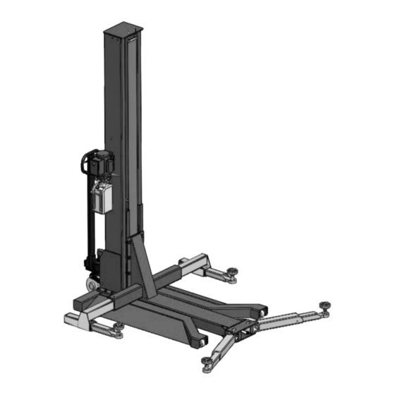
I. PRODUCT FEATURES AND SPECIFICATIONS Fig.1 MOBILE CHAIN-DRIVE SINGLE POST MODEL SML-7 · Compact design. · High quality cylinders and power units are manufactured to high standards. · Self-lubricating UHMW Polyethylene sliders and bronze bush. · Single-point safety release, and dual safety design. - Page 4 Arm Swings View Fig.2...
-
Page 5: Installation Requirement
II. INSTALLATION REQUIREMENT A. TOOLS REQUIRED Screw sets Level Bar Tape Measure(7.5mm) English Spanner(12″) Pliers Socket Head Wrench Wrench set:(10 # # # # 、13 、14 、12 # # # 、19 、24 、30 Fig.3 B. -
Page 6: Steps Of Installation
III. STEPS OF INSTALLATION A. Location of installation Check and insure the installation location (concrete, layout, space size etc.) is suitable for lift installation. B. Check the parts before assembly 1. Packaged lift and hydraulic power unit (See Fig. 4) Column Power unit Platform and... - Page 7 2. Take off the packaging on the machine Take off the packing rack. 3. Move aside the parts and check the parts according to the shipment parts list (See Fig.5 & 6) Shipment list Fig.5 Fig.6 Parts Box (42) 4. Check the parts of the parts bag according to the parts bag list (See Fig. 7) Fig.7...
- Page 8 C. Lay the base flat to the ground, confirm installation place according to the ground state, the main purpose is to save space. (See Fig.8) Fig.8 D. Install column and lift platform 1.Lay the column flat to the ground. (See Fig.9) Fig.9 2.Connecting oil hose of cylinder.
- Page 9 3. Fix column to the base plate. (See Fig.11) 4. Fix lifting platform to carriage. (See Fig.12) Fig.12 Fig.11...
- Page 10 D. Install cover of the safety device, retainer and protective cover (See Fig.13) After install the retainer, tighten slightly with M6*8 cup-head bolt. Install safety device as below Fig.13...
- Page 11 E. Install power unit and oil hoses (See Fig.14) Note: Tighten the oil hose fitting and power unit fitting to avoid oil leakage; Pay attention to the direction of power unit fitting. Tighter the screw with 19# wrench set after installing power unit fitting.
- Page 12 F. Install plastic cover (See Fig.15) Support plate for chain clip 链夹支撑板 Plastic baffle across 塑胶挡板从此处穿过 from here Fig.15 G. Install electrical system Connect the power source on the data plate of power unit. Note: For the safety of operators, the power wiring must contact the earth well. Single phase motor 1.
- Page 13 H. Install lifting arms Lowing the carriages down to the lowest position, fix cup head bolt M8*12 (see Fig.17) then tighten the screw (See Fig. 18). Fig.17 Operation of Arm Lock Handle ② ① ① Pull out the control handle. ②...
- Page 14 I. Install wheel assembly 1. First tighten the wheel assembly fixed square pipe by socket bolt with lock washer φ12 (Fig.19). Put the wheel assembly into the fixed square pipe then tighten it. (Fig.20), Fig.19 Fig.20 2. Insert the wheel assembly connecting board and fixed by elastic latch (Fig.21). Elastic Latch Fixing Pin Fig.21...
- Page 15 K. Using level to measure and adjust the column to be vertical (Fig.23). Use level to measure the column by front and side to make sure the column is vertical 34/35 Shim Fig.23...
-
Page 16: Exploded View
IV. EXPLOEDED VIEW 四、爆炸图 10~13 16~18 22~24 27 28 Fig.24... - Page 17 PARTS LIST FOR SML-7 Item Part# Description QTY. Note 10209009 Cup Head Bold M6*8 10209008 Safety Cover 11206002 Safety Pin 10209007 Safety Spring 11203263 Power Side Safety Device 11203013 Coupling 10209012 Elastic Pin (φ3.2) 10420049 Split Pin φ2*16 10101028 Wheel Assy.
- Page 18 Item Part# Description QTY. Note 10203054 Rubber Pad Assy. 10101033 Outside Lifting Arm Assy. 1101015001 Snap ring Φ13*Φ10*Φ1.5*32 85090128 Socket Bolt M8*20 10101008 Arm lock 11101009-01 Arm lock fixed plate 85090245 Socket bolt M5*12 1101012008 Limit sleeve φ10*6.2 1101012002 Connecting block 1101012004A Arresting Stop 1101015001...
- Page 19 1. Rubber Pad Assy.(10203054)Exploded View: Fig. 25 Description Item Part# 10420043 Hex Bolt M8*20 Rubber pad 10203043 Support pad assy. 11203026 10203041 Retaining ring 11203025 Adjusting screw 10203042 Retaining ring 11203024 Adjustment Screw 2. Outside Lifting Arm (10101033) Exploded View: Fig.
- Page 20 3. Inside Lifting Arm-Left (10102029) Exploded View: Item Part# Description QTY. 1021149 Cup Head Bolt M8*12 11102610 Inside Arm (Outer-left) 11203101 Inner Arm Fig. 27 4. Inside Lifting Arm-Right (10102028)Exploded View: Item Part# Description QTY. 1021149 Cup Head Bolt M8*12 11102612 Inside Arm (Outer-right) 11203101...
- Page 21 Item Part# Description QTY. 11207006 Pin for Chain Pulley Φ35*93 10420132A Bronze Bush Φ41.2*Φ35.1*20 11530023 Washer Φ44*Φ35.5*2 11207007 Chain Pulley Φ105*50 10430138 Socket Bolt M6*16 10209149 Lock washer Φ6 10420045 Washer Φ6 11207693 Chain limit block 10530042 Bronze Bush Φ41.2*Φ35.1*28 11207008 Chain Pulley Seat 6.
- Page 22 7. Manual Power Unit (071103) Exploded View: 110V/60HZ/1 Phase Manual Fig. 31...
- Page 23 PARTS LIST FOR MANUAL POWER UNIT (071103) ITEM Part# Description QTY. Note Rubber pad 81400180 Start capacitor 81400250 Run capacitor 81400200 Cup Head Bolt with Washer 10420148 Cover of capacitor 81400066 Motor connecting shaft 81400363 Manifold block 81400362 Lock Wash 10209149 Iron Plug 81400276...
- Page 24 8. Manual Power Unit (071104)Exploded View: 220V/60HZ/1 Phase Manual Fig. 32...
- Page 25 PARTS LIST FOR MANUAL POWER UNIT (071104) ITEM Part# Description QTY. Note Rubber pad 81400180 Start capacitor 81400250 Run capacitor 81400200 Cup Head Bolt with Washer 10420148 Cover of capacitor 81400066 Motor connecting shaft 81400363 Manifold block 090101 Lock Wash 10209149 Iron Plug 81400276...
-
Page 26: Test Run
Illustration of hydraulic Valve for hydraulic power unit Up Button Relief valve Oil return port Release Valve Throttle Oil output port valve Handle for Oil output port release valve Check Valve Fig. 32 V. TEST RUN 1. Adjust the lower speed (Fig.33) You can adjust the lower speed of the lift if needing: Turn the Throttle Valve in clockwise direction to decrease the lower speed, or increase the speed in counterclockwise direction. - Page 27 2. Test with load After finishing the above adjustment, test running the lift with load. Lift the lift in low position for several times first, make sure the lift can rise and lower without improper. And then test run the lift to top position completely. If there are anything improper, repeat the above adjustment.
-
Page 28: Operation Instruction
VI. OPERATION INSTRUCTIONS To lift vehicle 1. Keep clean of site near the lift; 2. Position lift arms to the lowest position; 3. To shortest lift arms; 4. Open lift arms; 5. Position vehicle beside of the lifting arm, car should at the other side of the column; 6. -
Page 29: Maintenance
VII.MAINTENANCE SCHEDULE Monthly: 1. Check all connectors, bolts and pins to insure proper mounting; 2. Lubricate cable with lubricant; 3. Make a visual inspection of all hydraulic hoses/lines for possible wear or leakage; 4. Check Safety device and make sure proper condition; 5. -
Page 30: Trouble Shooting
VIII. TROUBLE SHOOTING TROUBLE CAUSE REMEDY Button does not work 1. Replace button Wiring connections are not in good 2. Repair all wiring connection condition Motor does AC contactor burned out 3. Repair or replace contactor not run Motor burned out 4. - Page 31 Address: 1931 Jo Rogers Blvd, Manning, South Carolina,USA No:72215208 Date:2022/08...
Need help?
Do you have a question about the SML-7 and is the answer not in the manual?
Questions and answers