Table of Contents
Advertisement
Quick Links
Advertisement
Table of Contents

Related Manuals for AMGO Hydraulics PRO-12SX


Summary of Contents for AMGO Hydraulics PRO-12SX
- Page 1 Original PRO-12SX PRO-12ASX FOUR-POST LIFT Model: PRO-12SX PRO-12ASX...
-
Page 2: Table Of Contents
CONTENTS Product Features and Specifications ............. 1 Installation Requirement ..............2 Steps of Installation ................4 Exploded View ................. 22 Test Run ..................30 Operation Instruction ............... 31 Maintenance ................... 31 Trouble Shooting ................32 Lift Disposal..................32... -
Page 3: Product Features And Specifications
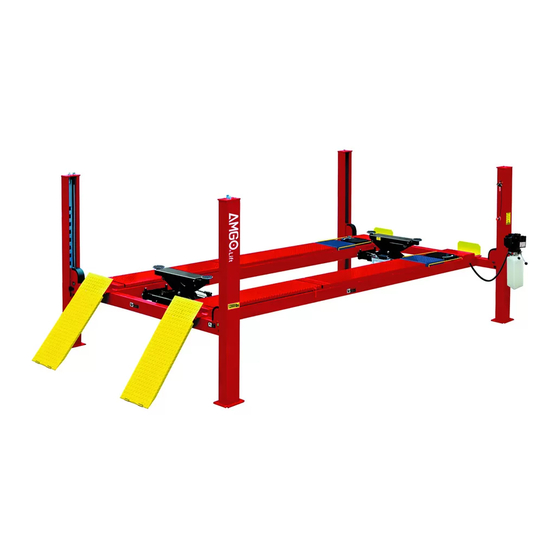
· Manual hydraulic power system, cable-drived. · Non-skid diamond platforms. · Adjustable platform and adjustable safety lock ladders. · Optional Jack: With hand pump/Air-operated hydraulic pump/Controlled by power unit. . Optional Turnplates:(only for PRO-12ASX) PRO-12SX PRO-12ASX Fig.1 Fig.2 MODEL PRO-12S(AS) SPECIFICATIONS Overall... -
Page 4: Installation Requirement
II. INSTALLATION REQUIREMENT A. TOOLS REQUIRED Rotary Hammer Drill (Φ3/4’’) Carpenter’s Chalk Hammer Screw Sets Level Bar Tape Measure (7.5m) English Spanner (12") Pliers Wrench Set Lock Wrench , 12 , 13 , 14 , 17 , 19... - Page 5 B. Equipment storage and installation requirements. The equipment should be stored or installed in a shady, normal temperature, ventilated and dry place. C. The equipment should be unload and transfer by forklift. (See Fig.4) × √ Fig. 4 D. SPECIFICATIONS OF CONCRETE (See Fig.
-
Page 6: Steps Of Installation
III. STEPS OF INSTALLATION A. Location of installation Check and insure the installation location (concrete, layout, space size etc.) is suitable for lift installation. B. Check the parts before assembly 1. Packaged lift and hydraulic power unit (See Fig. 6) Fig. - Page 7 5. Move aside the parts and check the parts according to the shipment parts list (See Fig. 9). PRO-12SX Fig. 9 PRO-12ASX Fig. 10...
- Page 8 6. Open the carton of parts and check the parts according to the parts box list (See Fig. 11) Fig. 11 7. Check the parts of the parts bag according to the parts bag list (See Fig. 12) PRO-12SX Part box(1) PRO-12ASX Part box(1) Parts bag (2)
- Page 9 Make sure the size is right and base is flat (see Fig. 13). Note: Reserve space front and behind the installation site. Use a carpenter’s chalk line to Car in Direction establish installation layout Fig. 13 MODEL REMARK PRO-12SX 196-3/4” 132-1/8” 237” PRO-12ASX...
- Page 10 D. Install cross beams (See Fig. 14, Fig. 15) Hole towards inside Fig 14 Fig. 15...
- Page 11 E. Fix the anchor bolts 1. Prepare the anchor bolts (See Fig. 16). Spring washer Washer Fig. 16 2. Using the prescribed rotary hammer drill, and drill all the anchor holes and install the anchor bolts. Do not tighten the anchor bolts (See Fig.
- Page 12 2. Install safety ladders (See Fig. 19). This height should be the same for four safety ladders Safety ladder pass through the hole of the top plate, then tighten the two nuts Fig. 19 G. Put the cross beams at the same height (See Fig.
- Page 13 H. Install power-side platform. 1. Put the power-side platform upon the cross beams by forklift or manual, offset the cross beams to the outside till the pulleys of both platforms can set up into the cross beam , Install the power-side platform and screw up the bolts (See Fig.21,22) (See Fig.23)
- Page 14 I. Assembly offside platform and slider block, check the (See Fig. 24) plumbness of columns with level, adjusting with the shims if not, and then tighten the anchor bolts (See Fig. 25). Measure the verticality of the four columns with a level to ensure that the columns are perpendicular to the ground.
- Page 15 J. Illustration for cable installation (See Fig. 26). 1. Pass through the cables from the platform to the columns according to the number of the cables Fig. 26 ○ ○ ○ ○ Cable Length 146-5/8” 398-5/8” 209-5/8” 335-3/8” (w/ fitting)
- Page 16 2. The cable pass through the cross beam to top plate of columns and be screwed with cable nuts then install the cable limit pin. (See Fig. 27, 28), (See Fig. 29) Cable pass through top plate and be Cable pass through screwed with cable between the big pulley nuts.
- Page 17 3. Illustration for platform cables (See Fig. 30, 31, 32). Limit Slider cable ④ cable ② cable ④ cable ② cable ③ cable ① Fig. 30 cable ④ cable ④ cable ③ cable ② cable ② cable ① Fig. 31 cable ②...
- Page 18 K. Install oil-water separator, manual control air valve and power unit (See Fig. 33). Air inlet Air outlet air direction The side marking “P” on the air valve is Air Input. direction Fig. 33...
- Page 19 L. Install hydraulic system Note: Oil hoses and oil return pipe connected to oil cylinder must be passed above the cable and cylinder inlet port must swing upward to avoid the oil hose and oil return pipe scratched by cable. Oil and air pipes through the clamp...
- Page 20 M. Install air-line system 1. Connecting front and rear Cross Beam cylinders by using 6*4 black air pipe. (the actual length of air line can be cut by user) ( See Fig.38 2, Cut the 6*4 black air pipe by scissor between two retainers, then connect the air line with T fitting.
- Page 21 4. Connecting Oil-water separator and Manual control air valve using air line (See Fig. 41) Oil-water separator Connecting Oil-water separator and Manual control air valve using black air line Manual control air valve Air pipe ¢6×¢4 Fig. 41 5. Connecting air inlet (Air supply pressure 5 kg/cm - 8 kg/cm ), adjusting the air pressure of Oil-water separator to 0.8 MPa...
- Page 22 O. Install Electrical System Connect the power source on the data plate of Motor. Note: 1. For the safety of operators, the power wiring must contact the floor well. 2. Pay attention to the direction of rotations when using 380V, three phase motors.
- Page 23 P. Install drive-in ramp, tire stop plate, platform lock plates (See Fig. 45 Install Drive-in ramp Install Tire stop plate The lock plates are used to prevent the turning & slipping of offside platform, Using Hex bolt M8*20 for the connection.
-
Page 24: Exploded View
IV. EXPLODED VIEW PRO-12SX Fig. 46... - Page 25 PRO-12ASX When installing the turntables, both sides are required a 35mm-high turntable block. Fig. 47...
- Page 26 PARTS LIST FOR PRO-12SX, PRO-12ASX Item Part# Description PRO-12S PRO-12AS 11420011A Power-side Column 11420002 Offside Column 10480040 Cross Beam Assy. 10420239 Slider block 10209059 Anchor Bolt 11410022 Safety Ladder 10420175A Hex Nut 11490001 Power-side Platform 11496001 11420022A Pulley Shaft Weldment...
- Page 27 Item Part# Description PRO-12S PRO-12AS 10420005 Fixing Bolt 10420502 Part box 10430501 Part box 11420031-1 Tire stop plate 10201005 Split pin 10620065 Shim 1mm 10201090 Shim 2mm 10209056 Self-locking Nut 11420217 Cable limit pin 11420007 Plate for Adjustable Turnplate 11410090 Cylinder fixing ring 10410081 Cylinder...
- Page 28 4.1CROSS BEAM (10480040) Fig. 48 Item Part# Description Note 11480023 Cross Beam 10420051B Pulley Safety Cover 10209009 Cup Head Bolt 11420044 Limit Plate 10420138 Socket Bolt 11420038 10420037 Snap Ring 10420033 Spring 10209021 Hex Nut 3-10 10420049 Split Pin 3-11 10420048 Air Cylinder 3-12...
- Page 29 4.2 CYLINDERS (10410081) Fig. 49 Item Part# Description Note 51-1 10420059 Dust Ring 51-2 10420060 Y- Ring 51-3 11410082 Head Cap 51-4 10410083 O- Ring 51-5 11410084 Bore Weldment 51-6 11420064 Piston Rod 51-7 11410085 51-8 10410086 Support Ring 51-9 10410087 Y- Ring 51-10...
- Page 30 Power unit (071101) explosive view Fig. 50 Single phase,220V/60Hz Part no Name Part no Name 81400180 Rubber pad 41030055 AC contractor 81400130 Starting 81400287 AC contractor capacitor 81400088 Running 71111216 Motor wiring capacitor cover 10420148 Screw with 81400560 Throttle valve washer 81400066 Capacitor cover...
- Page 31 Illustration of hydraulic valve for power unit Oil return port Relief valve Release valve Check valve Throttle Oil outlet valve Handle for relief valve Fig.51 4.3.1 Adjust the lower speed You can adjust the lower speed of the lift if needing: Turn the Throttle Valve in clockwise direction to decrease the lower speed, or increase the speed in counterclockwise direction.
-
Page 32: Test Run
V. TEST RUN 1. Fill the reservoir with approximately 11 L Hydraulic Oil (Note: In consideration of Power Unit’s durability,please use Hydraulic Oil 46#). Press button UP, the Cables will be strained. Check whether the Cables match the Pulley. Make sure the Cables are not across. 3. -
Page 33: Operation Instruction
VI. OPERATION INSTRUCTIONS To lift vehicle 1. Keep clean of environment near the lift; 2. Drive vehicle to the Platform and put on the brake; 3. Turn on the power and press the button UP, raise the lift to the working position; Note: make sure the vehicle is steady when the lift is raised. -
Page 34: Trouble Shooting
VIII. TROUBLE SHOOTING TROUBLE CAUSE REMEDY 1. Button does not work 1.Replace button 2.Wiring connections are not in good 2.Repair all wiring connections condition Motor does 3. Motor burned out 3.Repair or replace motor not run 4. AC contactor burned out 4.Replace AC contactor 5. - Page 35 AMGO HYDRAULIC CORPORATION 1931 Joe Rogers Blvd, Manning, South Carolina, Zip: 29102 Tel: (803) 505-6410 Fax: (803) 505-6410 图 72147501 Manual no: 修 Revised date:2019/12...
Need help?
Do you have a question about the PRO-12SX and is the answer not in the manual?
Questions and answers