Advertisement
Quick Links
Advertisement

Related Manuals for AMGO Hydraulics 407-P


Summary of Contents for AMGO Hydraulics 407-P
- Page 1 Original Four Post Parking lift Model: 407-P...
-
Page 2: Table Of Contents
CONTENTS Product Features and technical Specifications ..........1 Installation Requirement ................2 Steps of Installation ................4 Exploded View ..................28 Test Run ………..................33 Operation Instruction ................34 Maintenance ..................34 Trouble Shooting ...................36 Lift safety tips..................36... -
Page 3: Product Features And Technical Specifications
I. PRODUCT FEATURES AND SPECIFICATIONS 4-POST MODEL 407-P FEATURES · Single cylinder drive, Cable drive. · Single point manual safety release. ·The primary safety device of automatic machinery and the secondary safety device of cable breaking in the process of rising ensure the safety of the vehicle. -
Page 4: Installation Requirement
II. INSTALLATION REQUIREMENT A.TOOLS REQUIRED Tape Measure (7.5m) Carpenter’s Chalk Hammer Screw Sets Level Bar Pliers English Spanner (12") Lock Wrench Wrench set # # # # # :(12 、13 、14 、15 、17 、19... - Page 5 C. The equipment should be unload and transfer by forklift. Fig.3 D.SPECIFICATIONS OF CONCRETE (See Fig. 4) Specifications of concrete must be adhered to the specification as following. Failure to do so may result in lift and/or vehicle falling. 1. Concrete must be thickness 100mm minimum and without reinforcing steel bars,and must be dried completely before lift installation.
-
Page 6: Steps Of Installation
III. STEPS OF INSTALLATION A. Check the parts before assembly 1. Packaged lift and Hydraulic Power Unit (See Fig. 5) Fig. 5 Plastic oil tray Optional 油盘(选购件) 2. Open the outer packing carefully, check the parts according to the shipment list. (See Fig. - Page 7 5. Move aside the parts and check the parts according to the shipment parts list (See Fig. 8). Fig. 8 6.Open the carton of parts and check the parts according to the parts box list (See Fig. 9) Fig. 9...
- Page 8 Make sure the size is right and base is flat (see Fig. 11). Note: Reserve space front and behind the installation site. Use a carpenter’s chalk line to establish installation layout Fig. 11 MODEL 3862mm 2509mm 4605mm 407-P (152”) (98 3/4”) (181 3/8”)
- Page 9 C. Install cross beams (Note that Hole of the beam towards inside and the side with the rotating component of the safety mechanism should be the same side as the column where the power unit is installed. See Fig.12 & 13) The power-side column need to be installed close to the rotational safety device.
- Page 10 D. Install the Safety Ladders. 1. Take off the pulley safety cover and unscrew a nut of the safety ladders, and then adjust the four lower nuts to be at the same position. Then install the safety ladder (See Fig. 14). Unscrew A nut on the safety ladders.
- Page 11 2.Install Safety Ladders (See Fig. 15). This height should be the same for four safety ladders Safety ladder pass through the hole of the top plate, then Fig. 15 tighten the two nuts E.Put the cross beams at the same height and lock on the safety ladder (See Fig.
- Page 12 F. Install power side platform. 1. Install the power-side platform on the cross beams by a fork lift or manual, offset the cross beams to outside a little until the pulleys of both platforms enter into the cross beams opening .
- Page 13 2. Install tire stop plate with bolts and washer on the platform: Tighten the platform on cross beam B with bolts, tighten the tire stop plate on cross beam A with bolts Note: The bolts for the side with tire stop plate is longer, pay attention when choosing the bolts (See Fig.18) Instruction: 1).
- Page 14 G.Install offside platform and plastic block, then install the bolts for the platform strengthen plate, check the plumbness of columns with level and adjusting with the shims (See Fig. 19) Level bar Install the bolts for the platform strengthen plate Position the slide blocks along the bent...
- Page 15 H. Illustration for cable installation 1. Pass through the cables from the platform to the columns according to the number of the cables (See Fig. 20) Cable installation diagram Fig. 20 ○ ○ ○ ○ Cable Length 4264 mm 9529 mm 5684 mm 8112 mm (inc.
- Page 16 2. The cable goes through the cross beam to top plate of columns and be screwed with cable nuts (See Fig. 21). After the cable passes through the hole in the roof, cover the cable gasket and lock the nut. The cable adjusting sleeve (17B) does not need to be installed in the first use, and the cable...
- Page 17 3. Illustration for platform cables (See Fig. 22). Cable ③ Cable ④ Cable ○ 2 Cable ○ 4 Cable ○ 2 Cable ① Cable④ Cable② Cable① Cable③ Hex Bolt M10*90 Cable ② Cable ④ Fig. 22...
- Page 18 I. Install release handle assy. See Fig.23 Noted: Power unit must be installed near the safety release handle. Cross beam B 横梁B View B Cross beam A 横梁A View A Fig. 23 A 方向 图二十三 Safety lock Safety lock rotated device connecting bar Safety lock connecting...
- Page 19 J. Install power unit and connecting tube (See Fig. 24) Noted: Power unit must be installed near the safety release handle. 1. Install Power unit on the cross beam A Drive- in direction Cross beam B Cross beam A Fix the connecting tube and the connecting bar for safety device by M8*25 socket bolts (Connecting tube pass through the fixing plate) Fig.
- Page 20 2. Install Power unit on the cross beam B (See Fig. 25) Cross beam B Car-in direction Fix the connecting tube and the connecting bar for safety device by M8*25 socket bolts (Connecting tube pass through the fixing plate) Fig. 25...
- Page 21 K. Install Hydraulic System 1. For power unit attached to the column of cross beam A (See Fig. 26) Note: Oil hoses connected to oil cylinder must be passed above the cable to avoid the oil hose scratched by cable. Retainer Oil return hose Oil return...
- Page 22 For power unit attached to the column of cross beam B (See Fig. 27) Note: The oil return hose can be adjusted when installation. c、d Fig. 27 L. Install Electrical System Connect the power source on the data plate of Power Unit. Note: For the safety of operators, the power wiring must contact the floor well.
- Page 23 M. Install spring and safety cover of cross beam (See Fig. 29). Fig. 29 N. Install drive-in ramp, optional jack tray and optional plastic oil pans (See Fig. According to the below diagram screw up the M16*30 bolts, then attach the drive-in ramp.
- Page 24 O. Install Rear wheel stop plates (See Fig. 31) After driving the vehicle on the lift, take off the drive-in ramp, install rear wheel stop plates to the drive-in ramp position. Fig. 31 P. For optional kits installation. 1. Install optional caster kits (See Fig.
- Page 25 Item Part# Description QTY. Note 73-1 11410042A Support bracket 73-2 10209125 Hex bolt 73-3 10209039 Lock washer φ10 73-4 10209022 Washer φ10 73-5 10209021 Hex nut M10 73-6 10410035 Plastic wheel 73-7 11410034 Connecting pin φ19*216 73-8 10209012 Hair Pin φ3.2 2.
- Page 26 1.2 Using the prescribed rotary hammer drill, and drill all the anchor holes and install the anchor bolts. Do not tighten the anchor bolts (See Fig. 36). Note: The tightening torque for the anchor bolt is 150N.m ,Anchor bolts driven into the ground at least 90mm Bolt Borehole...
-
Page 27: Exploded View
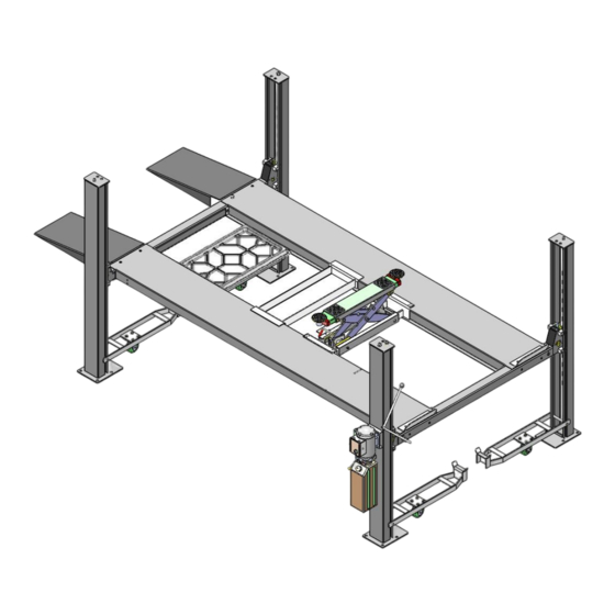
IV. EXPLODED VIEW Model 407-P Fig. 37... - Page 28 Power-side platform Fig. 38 PARTS LIST FOR MODEL 407-P Item Part# Description QTY. Note 11410002 Power-side Column 11410001 Offside Column Cross Beam A 1104542001B 1104543001B Offside Platform 1104543001A Power-side Platform Cross Beam B 1104542001B 1104543010 Drive-in ramp 10201002 Hex Bolt M8*16 10209033 Washer φ8...
- Page 29 Item Part# Description QTY. Note 1004546000 Cylinder φ80*876 1104533013A-01 Piston rod connecting seat 10410012 Hex Nut M24 10201005 Split Pin φ4*50 81513006 Manual Power Unit 10420175A Hex nut M20 10209066 Hex nut M16 1104541002 Adjusting sleeve of cable 1104541001 Cable gasket 11410022 Safety ladder L=1974 1104543009A...
- Page 30 Item Part# Description QTY. Note 10209004 Rubber ring φ8*φ20*3 10209003 Hex Bolt M8*25 10420166 Fitting 11420243 Straight Fitting for cylinder 11420245 Limit block 11209119 Compensation Valve 10201020 90°degree fitting 1004543005 Oil hose 10420120 Extend straight fitting with nut 1004543008 Oil hose 10209060 Fitting for power unit 10420095...
- Page 31 4.1 CYLINDERS(1004536000) Fig. 39 Parts For Cylinder Item Part# Description QTY. Note Dust ring Ф30*Ф38*(5~6.5) 12-1 10420059 12-2 10420060 Y- Ring IDI Ф30*Ф40*8 12-3 11420061 End cover 12-4 10420062 O- Ring Ф81.5*3.55 12-5 1004546001A Cylinder components 12-6 1104546002 Piston Rod 12-7 11420065 Cylindrical pin...
- Page 32 4.2 CROSS BEAM (10410003/10410006) 3-21 3-20 3-22 3-23 3-10 3-18 3-13 3-12 3-19 3-11 3-16 3-14 3-17 3-15 Fig.40 Parts For cross beam Item Part# Description QTY. Note 10206024 Hex Bolt M12*25 10206032 Snap Ring φ25 10217020 Bronze Bush φ31*φ25.1*16 10410099 Spring φ14*φ2.5*100 1104542008...
- Page 33 4.3 Manual Power Unit (071103) Fig. 41 Parts list for 110V/60Hz, Single Phase Item Part No. Description 81400180 Rubber Pad 80101034 Starting capacitor 10420148 Cup head bolt with washer 81400527 Protective cover for capacitor 81400363 Motor Connecting Shaft 80101013 Manifold block 10209149 Lock Washer 81400276...
- Page 34 81400530 Motor terminal box 10420070 Switch button 81400559 AC contactor 80101039 America wire and plug 81400528 Motor terminal box cover 81400560 Throttle valve 81400266 Relief valve 81400284 Socket iron plug 81400452 Hair pin 81400451 Release valve handle 10209020 Plastic ball 81400421 Release valve nut 81400422...
-
Page 35: Test Run
V. TEST RUN 1. Fill the reservoir with Hydraulic Oil (Note: In consideration of Power Unit’s durability, please use Hydraulic Oil 46#). Press the control button on the power unit till the cables are strained. Check the cables and confirm they are in the proper pulley position. Make sure the cables are not across. 3. -
Page 36: Operation Instruction
VI. OPERATION INSTRUCTIONS To lift vehicle 1. Keep clean of environment near the lift. 2. Drive vehicle to the platform and put on the brake. 3. Take off the drive-in ramp, install rear wheel stop plates to the drive-in ramp position. 4. -
Page 37: Maintenance
Oil cylinder maintenance: In order to extend the service life of the oil cylinder, please operate according to the following requirements. Recommend to use N46 anti-wear hydraulic oil. The hydraulic oil of the lifts should be replaced regularly during using. Replace the hydraulic oil 3 months after the first installation, Replace the hydraulic oil once a year afterwards. -
Page 38: Trouble Shooting
VIII. TROUBLE SHOOTING TROUBLE CAUSE REMEDY 1. Button does not work 1.Replace button 2.Wiring connections are not in good 2.Repair all wiring connections Motor does condition not run 3. Motor burned out 3.Repair or replace motor 4. AC contactor burned out 4.Replace AC contactor 1.Motor runs in reverse rotation 1.Reverse two power wire... - Page 39 AMGO HYDRAULIC CORPORATION 1931 Joe Rogers Blvd, Manning, South Carolina, USA Zip:29102 Tel: (803) 505-6410 fax: (803) 505-6410 服 Manual No.:043604000001 Revision Date: 2022/10...
Need help?
Do you have a question about the 407-P and is the answer not in the manual?
Questions and answers