Table of Contents
Advertisement
Quick Links
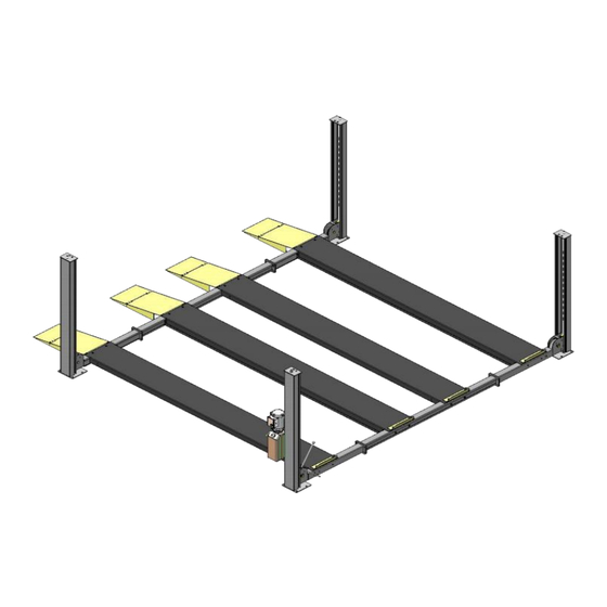
FOUR POST PARKING LIFT
Cargo Claims
If there is any missing or damage of
the cargo during transportation, the
buyer should claim on the carrier,
since the invoices issued by the
carrier is made out to the buyer.
MODEL: 409-DP 409-DPX
⚠
DANGER
Read
the entire contents of this manual
before
using this product. Failure to follow
instructions and safety precautions could
result in serious injury or even death. Make
sure all other operators also read this
manual.
Keep
this
machine so that it can be seen by all users.
By
proceeding
operation, you agree that you are fully
understand the contents of this manual and
take full responsibility for the use of the
product.
Original
manual
near
with
installation
the
and
Advertisement
Table of Contents

Related Manuals for AMGO Hydraulics 409-DP


Summary of Contents for AMGO Hydraulics 409-DP
- Page 1 Original FOUR POST PARKING LIFT MODEL: 409-DP 409-DPX ⚠ DANGER Read the entire contents of this manual before using this product. Failure to follow instructions and safety precautions could result in serious injury or even death. Make sure all other operators also read this manual.
-
Page 2: Table Of Contents
CONTENTS WARRANTY .................. 2 SAFETY INSTRUCTION ..............4 I. PRODUCT FEATURES AND SPECIFICATIONS ........6 II. INSTALLATION REQUIREMENT ............. 8 III. INSTALLATION STEPS ..............10 IV. EXPLODED VIEW ..............38 V. TEST RUN ................43 VI. OPERATION INSTRUCTIONS ............. 44 VII. MAINTENANCE SCHEDULE ............45 VIII. -
Page 3: Warranty
WARRANTY The warranty period for the steel structure part of new lift machine is 5 years, hydraulic components, bronze bush, slider and plastic parts warranty for years, electrical components and cable warranty for years, rubber pad is consumable without warranty. During the warranty period, the manufacturer will repair or replace the defective parts free of charge and bear the freight cost. - Page 4 SAFETY WARNING LABEL Fig. 1...
-
Page 5: Safety Instruction
SAFETY INSTRUCTION In order to properly maintain your product and ensure operator safety, it is the responsibility of the product owner to read and follow these instructions! 1. Ensure product installation complies with all applicable local regulations and rules, such as Occupational Safety and Health Administration regulations and electrical codes. - Page 6 14. Danger! The power supply used in this type of lift has high voltage. Please disconnect the power supply before any circuit repair. Unplug in case the power supply is accidentally switched on during maintenance. 15. Warning! There is a risk of explosion. There are parts in the equipment that produce arc light and spark.
-
Page 7: Product Features And Specifications
I. PRODUCT FEATURES AND SPECIFICATIONS Fig. 2 DOUBLE PARKING FOUR POST LIFT FEATURES Model 409-DP, 409-DPX · Cable transmission, drived by single hydraulic cylinder · Single point manual safety release, more convenient and reliable for decent operation. · Four mechanical locking devices, include primary mechanical safety lock with secondly cable-brake safety lock , ensure the vehicle safety. - Page 8 Capacity Time Length (inc. Length ( Not Between Through Width Height Height Ramps) Inc. Ramps) Columns Width 409-DP 9,000lbs 207 9/32" 173 13/16" 201 9/16" 192 1/16" 177 23/32" 82 7/8" 6 3/32" 409-DPX 9,000lbs 234 27/32" 201 3/8" 201 9/16"...
-
Page 9: Installation Requirement
II. INSTALLATION REQUIREMENT A.TOOLS REQUIRED Rotary Hammer Drill (Φ19) Carpenter’s Chalk Screw Sets Hammer Level Bar Tape Measure (7.5m) English Spanner (12") Pliers Wrench set Lock wrench , 13 , 14 , 15 , 17 , 19 , 24 , 30 ... - Page 10 B. Equipment storage and installation requirements. 1.Store the equipment in a dry, non-moldy, non-flammable environment. 2.The lift is generally approved for indoor installation and use. If need outdoor installation, the optional motor protect cover is required. (Kits No.: 40810) 3.When installing the device, take safety precautions according to the instructions to avoid device damage.
-
Page 11: Installation Steps
Fig. 6 Concrete intensity must be 3000psi (210kg/cm²) E. POWER SUPPLY 1.You are required to engage a licensed and qualified electrician for the installation process. 2.The power supply must be 220VAC single phase , with a cord larger than 3.3mm²( 12AWG), and must be properly grounded. - Page 12 3. Installation: The lift is only approved for indoor installation and use. If need outdoor installation, the optional motor protect cover is required. (Kits No.: 40810) 4. Floor: Install lift only on flat concrete floor. Do not install on asphalt or any other surface.
- Page 13 B. Check the parts before assembly. Make sure all parts of the lift are complete. 1. Packaged lift and hydraulic power unit(See Fig. 8). Fig. 8 2. Move the lift aside with a fork lift or hoist, unpack the lift, tear off the shipment parts list and check the components in the package according to the list.
- Page 14 4. Take out the parts in the offside platform, loosen the bolts of the middle package, take out the offside platform/power side platform of the middle package. (See Fig. Fig. 11 5. Take out the parts in the offside platform, take offer the package rack. 6.
- Page 15 7. Check the parts of the parts box according to parts box list (See Fig. 13). Only for 409-DPX Fig. 13 8. Check the parts of the parts bag according to parts bag list (See Fig. 14) Parts bag 1 Parts bag 2 Fig.
- Page 16 Note: Reserve space front and behind the installation site. Use a carpenter’s chalk line to establish installation layout Power side column Fig.15 MODEL 173 13/ 16" 201 9/ 16" 266 3/ 16" 409-DP 201 3/8" 201 9/ 16" 284 29/32" 409-DPX...
- Page 17 D. Install cross beam assy. 1. Prepare the assembly parts shown as below, see fig 16 3: Cross Beam W/O rotation device 2: Cross Beam Connection B W/ rotation device Note: Each cross beam has 4 W/ rotation device M16 nuts welded on one side, W/O rotation device and 2 M12 nuts welded on the Fig.16...
- Page 18 Enlarged view after installation. Make sure the window of cross beam connection towards inside Make sure the 2 M12 nuts welded on the cross beam are towards inside. Make sure the window of cross beam connection is towards inside. Cross Beam II Cross Beam I Make sure the 4 M16 nuts welded on the cross beam...
- Page 19 E. Assemble safety device coupling bar assembly,and bolted with cross beam assembly . 1. One safety device coupling bar assembly include one unit coupling bar, two units connecting bar, all parts see fig 19. 29 (coupling bar) L=150 25/32” (connecting bar) Φ8 lock washer Fig.19...
- Page 20 F. Install cross beam assy. to columns Noted: The windows of cross beam assy. should be towards inside, and the rotation devices should be at the same side of power side column. See Fig.22 Cross Beam II Power side column Cross Beam I Fig.22 The column with 4-Φ10 holes is power side, and...
- Page 21 G. Install the Safety Ladders. 1. Remove one nut from the safety ladders, and adjust the other nut to the proper install the position that all nuts of 4 safety ladders at the same position. Then safety ladders. (See Fig. 23). Remove one nut Adjust the other four nuts of safety ladders to...
- Page 22 2. Install Safety Ladders (See Fig. 24). This height of four threaded rods should be the same. Fig. 24 Pass the safety ladder through the hole of the top plate, then tighten the two nuts. H. Put the cross beams to the same height and lock at the safety ladder (See Fig.
- Page 23 I. Install power-side platform. 1. Install the power side platform on the cross beams by a fork lift or manual, offset the cross beams to outside a little until the pulleys of both platforms enter into the cross beams opening .
- Page 24 2. Install connecting bolts of power side platform and cross beam. Use the connecting bolts to connect the cross beam and platform, no need to tighten at this step. Note: Tire stop is installed at the front direction, the bolts for it are longer than for the rear side, please pay attention to it.
- Page 25 Pay attention to the difference of bend-strip edges of two models. 409-DPX 409-DP Fig. 28 2. Install platform connecting bolts, follow the same steps as power side platform. See fig 29. 38 (M16*35 Hex bolt with flat...
- Page 26 3. Install platform side connecting bolts and cross beam slide blocks. Finally, tighten all the connecting bolts of platform. 40 (M12*20 Hex Bolt with flat washer, lock washer) Install side connecting bolts Cross beam II Cross beam I Power side column 41 (M8*40 Socket Bolt with flat washer, nylok nut) Fig.
- Page 27 K. Install safety device connecting rod, Release handle and articulate bushing. 43 Coupling sleeve 44 Connecting rod Install safety device connecting rod and Release handle, see fig 31 Cross beam II Illustrated diagram Cross beam I of safety device Cross beam II Cross beam I ①Pass the end of connecting rod (with 2 holes) through the rotation device of inner side of...
- Page 28 ⑤ Install extended release handle and pull rope. Pull rope only available for 409-DPX 2. Install coupling sleeve Cross beam II Cross beam I Retaining Plate ① Pass the coupling sleeve through retaining plate, then put the safety device connecting bar (threaded side) into it. View from the bottom Fig.
- Page 29 Pay attention to the notch direction of cable connecting board. Don’t install in wrong direction . Fig. Cable installation diagram ○ ○ ○ ○ Cable 409-DP Length 115 3/4" 431 1/2" 267 5/16" 280 5/16" (inc. cable fitting) 409-DPX Length 128 29/32" 473 3/16"...
- Page 30 2. Pass The cables through the cross beam pulley and tension pulley, to top plate of columns and screw with cable nuts (See Fig. 34). Adjusting sleeve of cable Cable goes between the big pulley Cable goes to top plate of column and screwed and tension pulley with cable nuts.The adjusting sleeve of cable (35A) does not need initially.
- Page 31 ○ 4 Cable ○ 4 Cable ○ 2 Cable No.③ Cable ○ 1 Cable ○ 2 Cable Fig. 36 ○ 4 Cable ○ 2 Cable Fig. 37 4. Install tension spring and cross beam safety cover. (See Fig. 38). Fig. 38...
- Page 32 M. Install power unit Fixing the motor installing plate to the power side column. And install the power unit to the installing plate. See fig 39. Cross beam II Cross beam I Fixing the motor installing plate to the power side column Hex Bolt M8*20 with flat washer, lock washer and Hex Nut.
- Page 33 Install Hydraulic System 1. For power unit install to the column at the side of cross beam A (See Fig. 40) Note: Oil hoses connected to oil cylinder must be passed above the cable and cylinder inlet port should be upward a little to avoid the oil hose scratched by cable.
- Page 34 Adjust columns plumbness, Install the anchor bolts. 1.Check the plumbness of columns with leveling instrument and adjusting with the shims. Level Ruler Fig. 41 2.Prepare the anchor bolts (See Fig. 42). Washer lock washer Fig. 42 3.Use the prescribed rotary hammer drill, drill all the anchor holes and install the anchor bolts and tighten all nuts.
- Page 35 P. Install foldable drive-in ramp assembly Install the M16*30 bolts into the cross beam according to the below diagram, then hang the 4 units foldable drive-in ramps assy. on the bolts. See fig 44. Install the M16*30 bolts to the holes on the side of crossbeam.
- Page 36 Parts List of Foldable drive-in ramps assembly (1104533025C) Part Number Description 1104233003A Foldable drive-in ramps #1 1104233004A Foldable drive-in ramps #2 1104543021 Connect Pin 10209010 φ10 Snap Ring Q. Install optional plastic oil tray ( Kits No.40806) Plastic Oil Tray (1set, 4pcs) Fig.
- Page 37 R. Install optional Storage Wave Panels (Kits No.40812) Every lift can use 1 set or 2 sets 409-DP: Each parking unit need 17 units wave panels, 2 units adj. U-steels Fig. 47 409-DPX: Each parking unit need 20 units wave panels, 2 units adj.
- Page 38 S. Install Electrical System Connect the power source according to the data plate of Motor. Note: For the safety of operators, the power wiring must contact the floor well. Single phase motor Connect the two power supply wire (fire wire L and zero wire N) to terminals of AC contactor marked L1, L3 respectively.
-
Page 39: Exploded View
IV. EXPLODED VIEW Fig. - Page 40 PARTS LIST Quantity Part No. Description 409-DP 409-DPX 11410001-01 Power side column 11410074-02 1104572012A Cross beam connection B 1104572007A Cross beam 1104572011A Cross beam connection A 11410002-01 Off side column 11410075-02 1104573001B Off side platform 1104583001B 1104533025C Foldable drive-in ramps assy.
- Page 41 Quantity Part No. Description 409-DP 409-DPX 10420175A Hex nut M20 1104571001 Adjusting sleeve of cable φ28*30 11410022 Safety ladder 11410073-01 1004574015 Hex bolt M16*30 (incl. lock washer, flat washer) 1004574016 Hex bolt M16*35 (incl.lock washer, flat washer) 11410015-1 Tire Stop Hex bolt M12*20(8.8GD)
- Page 42 Quantity Part No. Description 409-DP 409-DPX 10209060 fitting for power unit 10201090 Shim 5/64" 10620065 Shim 3/64" 10209059 Anchor bolts 3/4” x 5-1/2” 10410013 Hex Bolt M16*30 1004574009 Parts Box 1004584004 1104572003A Rotation device 4.1 CYLINDERS EXPLODED VIEW Fig. 51...
- Page 43 Parts List Quantity Item Part# Description 409-DPX 409-DP 12-1 Dust Ring 10420059 12-2 Y- Ring IDI 10420060 12-3 Head Cap 11410082 12-4 O- Ring 10410083 11410084 12-5 Bore Weldment 11410078-02 11420064 12-6 Piston Rod 11410079-02 12-7 11420065 12-8 10420066 Support Ring...
-
Page 44: Test Run
V. TEST RUN 1. Fill the oil tank with around 11L hydraulic oil (in order to ensure the service life of the hydraulic system and ensure the best condition of the equipment, please fill in #46 high-quality anti-wear hydraulic oil). 2. -
Page 45: Operation Instructions
VI. OPERATION INSTRUCTIONS Please read the safety tips carefully before operating the lift To lift vehicle 1. Keep clean of site near the lift; 2. Drive in the vehicles on platforms and apply the parking brake. 3. Power on, push the power unit UP button, lift the vehicles to the working position. Note: Make sure the vehicles are in steady safe status. -
Page 46: Maintenance Schedule
VII. MAINTENANCE SCHEDULE Monthly: 1. Lubricate cables. 2. Make visual inspection of cables for possible wear or damage. 3. Make visual inspection of hydraulic hoses for possible wear or leakage. 4. Lubricate all rollers, pins and safety devices with 90WT gear oil. Every six months: 1. -
Page 47: Trouble Shooting
VIII. TROUBLE SHOOTING TROUBLE CAUSE REMEDY 1. Start Button does not work 1. Replace start button 2. Wires in poor connecting 2. Repair wiring connections Motor does not 3. Motor burned out 3. Repair or replace motor 4. AC contactor burned out 4. -
Page 48: Car Lift Safety Tips
IX. CAR LIFT SAFETY TIPS Put this safety tips in a place where you can always alert the operator. Please reference to the lift manufacturer’s manual for specific information about the lift. 1. Check the lift daily. If the machine breaks down or has damaged parts, do not operate, and use original equipment parts to repair. - Page 49 AMGO HYDRAULIC CORPORATION 1931 Joe Rogers Blvd, Manning, South Carolina, USA Zip:29102 Tel: (803) 505-6410 fax: (803) 505-6410 Manual Part No.: 72149101 Revision Date: 2023/07...
Need help?
Do you have a question about the 409-DP and is the answer not in the manual?
Questions and answers