AMGO Hydraulics PRO-12ASX Installation And Service Manual
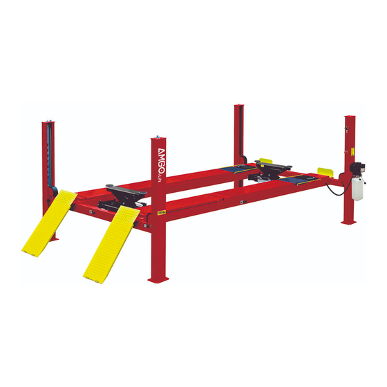
Four-post lift
Hide thumbs
Also See for PRO-12ASX:
- Installation and service manual (35 pages) ,
- Installation and service manual (42 pages)
Table of Contents
Advertisement
Quick Links
Advertisement
Table of Contents

Related Manuals for AMGO Hydraulics PRO-12ASX


Summary of Contents for AMGO Hydraulics PRO-12ASX
- Page 1 FOUR-POST LIFT Model: PRO-12ASX...
-
Page 2: Table Of Contents
CONTENTS Product Features and Specifications ............. 1 Installation Requirement ……………………………………………………………………………… 2 Steps of Installation …................ 3 Exploded View ................. 22 Test Run ……….................. 25 Operation Instruction ............... 26 Maintenance ................... 27 Trouble Shooting ................28 Parts List ..................29... -
Page 3: Product Features And Specifications
I. PRODUCT FEATURES AND SPECIFICATIONS ALIGNMENT 4-POST MODEL PRO-12A FEATURES · Manual-air control operation system. · Mechanical self-lock and air-drived safety release. · Non-skid diamond platforms. · Multiple turnplate blocks fits with different wheel base. · Adjustable platform and adjustable safety lock ladders. ·... -
Page 4: Installation Requirement
II. INSTALLATION REQUIREMENT A. TOOLS REQUIRED Rotary Hammer Drill (Φ19) Carpenter’s Chalk Hammer Screw Sets Level Bar Tape Measure (7.5m) English Spanner (12") Pliers Ratchet Spanner With Socket (28 Socket Head Wrench (3 ... - Page 5 B. SPECIFICATIONS OF CONCRETE (See Fig. 3) Specifications of concrete must be adhered to the specification as following. Failure to do so may result in lift and/or vehicle falling. 1. Concrete must be thickness 4’’ minimum and without reinforcing steel bars, and must be dried completely before the installation.
-
Page 6: Steps Of Installation
III. STEPS OF INSTALLATION A. Location of installation Check and insure the installation location (concrete, layout, space size etc.) is suitable for lift installation. B. Check the parts before assembly 1. Packaged lift and hydraulic power unit (See Fig. 4) Fig. - Page 7 5. Move aside the parts and check the parts according to the shipment parts list (See Fig. 7). Fig. 6. Open the carton of parts and check the parts according to the parts box list (See Fig. 8) Fig. 8...
- Page 8 7. Check the parts of the parts bag according to the parts bag list (See Fig. 9) Parts bag NO.2 Fig. 9...
- Page 9 C. Use a carpenter’s chalk line to establish installation layout as per Table 1 Make sure the size is right and base is flat (see Fig. 10). Note: Reserve space front and behind the installation site. Car in Direction Use a carpenter’s chalk line to establish installation layout Fig.
- Page 10 D. Install cross beams (See Fig. 11, Fig. 1 Hole towards inside Fig 11 Fig. 12...
- Page 11 E. Fix the anchor bolts Spring washer 1. Prepare the anchor bolts (See Fig. 13). Washer Fig. 13 2. Using the prescribed rotary hammer drill, and drill all the anchor holes and install the anchor bolts. Do not tighten the anchor bolts (See Fig.
- Page 12 2. Install safety ladders (See Fig. 16). This height should be the same for four safety ladders Safety ladder pass through the hole of the top plate, then tighten the two nuts Fig. 16 G. Put the cross beams at the same height (See Fig.
- Page 13 H. Install powerside platform. 1. Put the powerside platform upon the cross beams by fork lift or manual, offset the cross beams to the outside till the pulleys of both platforms can set up into the cross beams , Install the powerside platform and screw up the bolts (See Fig.18) (See Fig.19) Offset the cross beam lean...
- Page 14 I. Assembly offside platform and slider block, check the plumbness of columns with level, adjusting with the shims if not, and then tighten the anchor bolts (See Fig. 20). 3-15 3-16 Using the Ratchet Spanner With Socket to tighten the bolts 3-14 Install the slider block on the cross beam...
- Page 15 J. Illustration for cable installation 1. Pass through the cables from the platform to the columns according to the number of the cables (See Fig. 21). ○ ○ ○ ○ Cable Length ” 398-5/8” 209-5/8” 335-3/8” 146-5/8 (inc. connecting fitting) Fig.
- Page 16 2. The cable pass through the cross beam to top plate of columns and be screwed with cable nuts. Installation for Cable limit Pin on cross beam (See Fig. 22). Cable pass through Cable pass through top between the big pulley plate and be screwed and tension pulley with cable nuts.
- Page 17 3. Illustration for platform cables (See Fig. 23). Limit slider cable cable ② ④ cable ② cable ④ cable ③ cable ① cable ④ cable cable ③ ④ cable ② cable ② cable ① cable ② cable ④ Hex Bolt φ3/8”*4-3/4”...
- Page 18 K. Install oil-water separator, air solenoid valve, and power unit. (See Fig. 24). Air inlet Air outlet Air flow of oil water separator The ”P” side on air solenoid valve is for Air inlet flow Air flow of air solenoid valve Fig.
- Page 19 L. Install hydraulic system (See Fig. 25). Note: Oil hoses and oil return pipe connected to oil cylinder must be passed above the cable and cylinder inlet port must swing upward to avoid the oil hose and oil return pipe scratched by cable. Retainer Protective Ring cylinder inlet port...
- Page 20 2. Connecting front and rear Cross Beam cylinders by using ¢6×¢4 black air line (See Fig. 27). 3. Connecting manual controlled air valve by using¢6×¢4 black air line (See Fig. 27) 4.Diagram of oil hose and air hose (See Fig. 28) Air cylinder fitting Air cylinder fitting Rear...
- Page 21 5. Connecting oil-water separator and manual controlled air valve using air line (See Fig. Oil-water separator Connecting Oil-water separator and manual controlled air valve using black air line ¢8×¢6 Manual controlled air valve φ6*φ4 black air line Fig. 29 4. Connecting air inlet (air supply pressure 5kg/cm - 8kg/cm ), adjusting the air pressure of oil-water separator to 0.4 - 0.6MPa...
- Page 22 O. Install Electrical System Connect the power source on the data plate of Motor. Note: 1. For the safety of operators, the power wiring must contact the floor well. 2. Pay attention to the direction of rotations when using 380V, three phase motors.
- Page 23 P. Install drive-in ramp, tire stop plate, platform lock plates, steel ball set (See Fig. 36 Install Drive-in ramp Install Tire stop plate Fig. 33...
-
Page 24: Exploded View
IV. EXPLODED VIEW Model PRO-10A Fig. 34... - Page 25 CROSS BEAM Fig. 44 CYLINDERS Fig. 36...
- Page 26 Manual power unit Single phase 220V,60HZ Fig. 37 Manual power unit Single phase 220V,60HZ Manual power unit(See Fig.38) Protect ring Release valve Relief valve Oil return Check valve Throttle port valve Oil Outlet Handle for release valve Fig. 38...
-
Page 27: Test Run
V. TEST RUN 1. Fill the reservoir with approximately 12L Hydraulic Oil (Note: In consideration of Power Unit’s durability,please use Hydraulic Oil 46#). Press button , the Cables will be strained. Check whether the Cables match the Pulley. Make sure the Cables are not across. 3. -
Page 28: Operation Instruction
Circuit Diagram of Hydraulic System 1. Filter 2. Gear pump 3.Buffer valve 4. Relief Valve 5. Motor 6. Throttle Valve Hydraulic Solenoid Valve 8. Two-way Valve 9. Four post cylinder Fig.39 VI. OPERATION INSTRUCTIONS To lift vehicle 1. Keep clean of environment near the lift; 2. -
Page 29: Maintenance
released, press the handle of release valve by the other hand then the lift starts being lowered automatically; 3. Drive away the vehicle when the lift is lowered to the lowest position. 4. Turn off the power. VII. MAINTENANCE SCHEDULE Monthly: 1. -
Page 30: Trouble Shooting
VIII. TROUBLE SHOOTING TROUBLE CAUSE REMEDY 1. Button does not work 1.Replace button 2.Wiring connections are not in good 2.Repair all wiring connections condition Motor does 3. Motor burned out 3.Repair or replace motor not run 4. AC contactor burned out 4.Replace AC contactor 5. -
Page 31: Parts List
IX. PARTS LIST FOR MODEL PRO-12A Item Part# Description Note Power side column 11420011A Offside column 11420002 Cross Beam a 11480040 Limit slider 10420239 Anchor Bolt 10209059 Safety Ladder 11410022 Hex Nut 10420175A Powerside Platform 11496001 Pulley Shaft Weldment 42022A Washer 10420023A Pulley... - Page 32 Snap ring 10209010 Protective ring 10420156 Washer 10420045 Pin for drive in ramp 11420004 Fixing bolt 10420005 Parts box Tire stop plate 11420031 Split pin 10201005 10620065/10 Shim 20ea. 201090 Self locking nut 10209056 Cable limit pin 11420217 Cover for turnplate 11430004 Pin for side slider 11520037...
- Page 33 Oil return pipe 10420195 Air line 10420131A Black air line 10420167 Turnplate adjustment block 11480033 Turnplate adjustment block 11480045 Turnplate adjustment block 11440082 Parts for Cross Beam Cross beam assy 11480040 Safety cover for cross beam 10420051B Cup head bolt 10209009 Limit block 11420044...
- Page 34 Parts for Cylinder Dust ring 55-1 10420059 Y-ring 55-2 10420060 Head cap 55-3 11460046 O-ring 55-4 10460047 Bore weldment 55-5 11460048 Piston rod 55-6 11420064 55-7 11460050 Support ring 55-8 10460051 Y-ring 55-9 10460052 Piston 55-10 11460053 Parts for single phase 220V,60HZ manual power unit Rubber gasket 81400180 Start capacitor...
- Page 35 O-ring 10209069 Relief valve 81400266 Iron plug 81400284 Hair pin 10720118 Handle for release valve 10720121 Plastic ball for arm lock bar 10209020 Release valve nut 81400125 Shim for release valve 81400124 Valve seat(low) 81400449 Release valve 070001 Check valve 070002 Oil suction pipe 81400288...
- Page 36 服务手册编号:72149601 修订日期:2018/11...
Need help?
Do you have a question about the PRO-12ASX and is the answer not in the manual?
Questions and answers