Table of Contents
Advertisement
Quick Links
Advertisement
Table of Contents

Related Manuals for AMGO Hydraulics PRO-40


Summary of Contents for AMGO Hydraulics PRO-40
- Page 1 Original FOUR POST LIFT Model: PRO-40, PRO-40E...
-
Page 2: Table Of Contents
CONTENTS Product Features and Specifications ............. 1 Installation Requirement ..............2 Steps of Installation ................4 Exploded View ..................23 Test Run ……….................. 31 Operation Instruction ............... 32 Maintenance ................... 32 Trouble Shooting ................34 List Disposal..................34... -
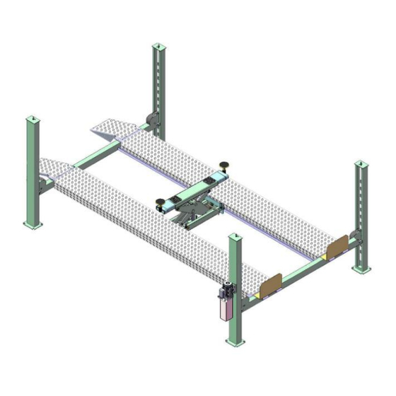
Page 3: Product Features And Specifications
● Manual hydraulic power system, cable-drived. ● Strengthen and Non-skid diamond platforms. ● Adjustable platform and adjustable safety lock ladders. ● Optional Jack: With Pneumatic hydraulic pump ● Model: PRO-40(E) Fig .1 MODEL SPECIFICATIONS Overall Width Lifting Lifting Lifting Overall... -
Page 4: Installation Requirement
II. INSTALLATION REQUIREMEN A TOOLS REQUIRED Rotary Hammer Drill ( Carpenter’s Ink Marker Φ3/4 Hammer Screw Sets Level Bar Tape Measure ( 295-1/4” English Spanner (12") Pliers Wrench Set : Lock Wrench #... - Page 5 B. SPECIFICATIONS OF CONCRETE (See Fig. 4) Specifications of concrete must be adhered to the specification as following. Failure to do so may result in lift and/or vehicle falling. 1. Concrete must be thickness 5” minimum and without reinforcing steel bars,and must be dried completely before the installation.
-
Page 6: Steps Of Installation
III. STEPS OF INSTALLATION A. Location of installation Check and insure the installation location (concrete, layout, space size etc.) is suitable for lift installation. B. Check the parts before assembly 1.The equipment should be unload and transfer by forklift. (See Fig.5) ×... - Page 7 5. Loose the screws of the upper package stand take off the offside platform take out the parts inside the power side platform then remove the package stand. 6. Move aside the parts and check the parts according to the shipment parts list (See Fig. Fig.9 .
- Page 8 8. Check the Parts bag according to the parts bag list (See Fig. 11) Parts bag 1 Parts bag 2 Fig.11 - 6 -...
- Page 9 Note: Reserve space before and behind the installation site. Car in Direction Use a carpenter’s chalk line to establish installation layout Offside column Power-side column Fig. 12 Model 315 1/2″ 161 3/8″ 354 1/2″ PRO-40 (8014mm) (4100mm) (9002mm) 374 1/2″ 161 3/8″ 407 7/8″ PRO-40E (9514mm) (4100mm) (10360mm)
- Page 10 D. Install cross beams (See Fig. 13) Hole towards inside Fig. 13 E. Fix the anchor bolts 1. Prepare the anchor bolts Spring washer (See Fig. 14). Washer Fig. 14 2. Using the prescribed rotary hammer drill, and drill all the anchor holes and install the anchor bolts, do not tighten the anchor bolts first (See Fig.
- Page 11 F. Install the safety ladders 1. Take off the pulley safety cover and unscrew the four upper nuts of the Safety Ladders, and then adjust the four lower nuts to be at the same position, then install the safety ladders (See Fig.
- Page 12 G. Put the Cross Beams at the same height (See Fig. 18). The four primary safety locks are adjusted to be locked to the safety ladders at the same time Lifting Both Cross Beams to the same height Lifting Both Cross Beams to the same height, it is recommended to about 1 meter height Fig.
- Page 13 H. Install power side platform. 1. Put the power-side platform upon the cross beams by fork lift or manual, offset the cross beams to the outside till the pulleys of both platforms can set up into the cross beam (See , Install the power side platform and screw up the bolts Fig.19) (See Fig.20)
- Page 14 I. Assemble offside platform and slider block. ( ), check the vertical of columns see Fig.21 with Level bar, adjust with the shims if not, and then tighten the anchor bolts (See Fig. 22) check the vertical of columns with Level bar, adjust with the shims Offside platform Power-side platform...
- Page 15 (See Fig. 23) 1. Pass through the cables from the platform to the columns according to the number of the cables Fig. 23 ○ ○ ○ ○ Cable 4915mm 14830mm 7115mm 12645mm PRO-40 6405mm 17775mm 8610mm 15580mm PRO-40E - 13 -...
- Page 16 2. The cable pass through the cross beam to top plate of columns and be screwed with cable nuts then install cable limit pin (See Fig. 24, Fig.25), (See Fig.26) Cable pass through between the Cable pass through top plate and big pulley and tension pulley be screwed with cable nuts.
- Page 17 3. Illustration for platform cables (See Fig. 27, Fig.28, Fig.29) Limit Slider cable ④ cable ④ cable ② cable ② cable ① cable ③ Illustration for Cable connection plate Fig.27 cable ④ cable ③ cable ④ cable ② cable ② cable ①...
- Page 18 K. Install oil-water separator, manual control air valve and power unit (See Fig. 30, Fig.31 ) Power-side column Air inlet Air outlet The side marking “P” on the air valve is Air Input. flow Air flow of manual-control Air Valve Fig.30 Fig.31 Item...
- Page 19 L. Install hydraulic system (See Fig. 32, Fig.33,Fig.34) Note: Oil hoses and oil return pipe connected to oil cylinder must be passed above the cable, cylinder inlet port must swing upward to avoid the oil hose and oil return pipe scratched by cable ( see Fig.34) Oil Hose and air...
- Page 20 Rear Cross Beam Fig.36 Connecting air solenoid valve using 8*6 black air line Item Part# Description PRO-40 PRO-40E 85090120 Y- Fitting for Air hose 10481065 Air Line φ8*φ6*11600mm (black) 10481027 Air Line φ8*φ6*13100mm (black) 10420167A Air Line φ8*φ6*460mm (black)
- Page 21 4. Connect Airline with oil-water separator and manual control air valve. (See Fig.38) Oil water separator Connecting Oil-water separator and manual controlled air valve using black air line 8*6 Manual-control air valve φ8*φ6 Airline Fig.38 5. Connecting air inlet (Air supply pressure 8 kg/cm ), adjusting the air pressure of Oil-water separator to 0.8 MPa (See Fig.39) Air Inlet...
- Page 22 N. Install Electrical System Connect the power source on the data plate of Motor. Single phase motor (See Fig. 40) Connecting the two power supply wires (active wire L and neutral wire N) to terminals of AC contactor marked L1, L3 respectively. Earth wire( yellow and green wire) is connected with the earth wire terminal of the motor Power supply wires Fig.
- Page 23 P. Install Drive-in ramp, Tire stop plate. (See Fig. 42,Fig.43) Install Drive-in ramp Install Tire stop plate Fig. 43 Fig.42 Q. Install Extension Kit (optional) 1. Lift the equipment to about 1400mm from ground, lock it to the safety ladder, remove the cable limit bolts and platform fixing bolts (see Fig.39, Fig 40) Then remove the platform fixing bolts...
- Page 24 Tire stop plate Extension Kit Platform fixing bolts Tighten the extension kit and platform with hex bolt M16*40, washers, spring washer and hex nut. Fig.46 Fig.47 Part# Description Quantity Available for 1044001 Extension Kit 1set (2 pcs) PRO-40, PRO-40E - 22 -...
-
Page 25: Exploded View
IV. EXPLODED VIEW - 23 -... - Page 26 Parts list for PRO-40 PRO-40E Item Part# Description PRO-40 PRO-40E 11481640 Power side Column 11481641 Offside Column 1104352002 Cross Beam Assy. 10481023 Slider block (HK018) 59*55*190 10201140 Anchor Bolt 3/4*6-1/2 16 sets 16 sets 11481036 Safety Ladder 10481018 Hex Nut M33*3.5...
- Page 27 11481016 Pin for Drive-in ramp Item Part# Description PRO-40 PRO-40E 10420005 Fixing bolt M5*8 10481500 Parts box 11481638 Tire stop plate 10481020 Split pin φ5*60 10620065 Shim (2mm) 10201090 Shim (1mm) 10206023 Self locking nut M12 11481046 Cable limit pin 10420016B Platform lock plate φ40*2*1500mm...
- Page 28 4.1 Cross beam ( 1104352002 ) Exploded View Fig 49 Item Part# Description 11400003 Cross Beam Assy. 11481618 Cross Beam Cover 10209009 Cap Head Bolt M6*8 Limit Plate 1104332001-01 10101029 Socket Bolt M12*20 3-5A 10420026 Spring Washer φ12 3-5B 10206006 Washer φ12 11481029...
- Page 29 3-19 11481032 Pin Bush For Slack-cable Safety Lock 3-20 10610008 φ30 Snap Ring 3-21 10209010 φ10 Snap Ring 3-22 10481027 Tension Pulley 3-23 11420174 Spacer 3-24 Pulley shaft 11481030-01 3-25 11481031 Pulley Bush 4.2 Cylinder (10400017) Exploded View 51-11 Fig. 50 Item Part# Description...
- Page 30 4.3 Power Unit (071107) Exploded View 220V/60Hz Single Phase Fig.51 Manual Power Unit Exploded View - 28 -...
- Page 31 Part lift for 220V/60Hz Single Phase Manual Power Unit Item Part# Description 81400180 Rubber pad 81400250 Start capacitor 81400200 Run capacitor 10420148 Cap head bolt 81400066 Capacitor cap 81400363 Motor Connecting Shaft 81400369 Manifold block 10209149 Spring washer 81400276 Iron plug 81400259 Red rubber plug 85090142...
- Page 32 Illustration of Hydraulic Valve for power unit (See Fig.52) Protective ring Oil return port Relief valve Release valve Throttle valve Handle of Release Oil Outlet valve Check valve Fig.52 - 30 -...
-
Page 33: Test Run
V. TEST RUN 1. Fill the reservoir with approximately 26L Hydraulic Oil (Note: In consideration of Power Unit’s durability,please use Hydraulic Oil 46#). 2. Press the button on the power unit, the Cables will be strained. Check whether the Cables match the Pulley. Make sure the Cables are not across. 3. -
Page 34: Operation Instruction
VI. OPERATION INSTRUCTIONS To lift vehicle 1. Keep clean of environment near the lift; 2. Drive vehicle to the Platform and put on the brake; 3. Turn on the power and press the button, raise the lift to the working position; Note: make sure the vehicle is steady when the lift is raised. - Page 35 Oil cylinder maintenance: In order to extend the service life of the oil cylinder, please operate according to the following requirements. 1. Recommend to use N46 anti-wear hydraulic oil. 2. The hydraulic oil of the lifts should be replaced regularly during using. Replace the hydraulic oil 3 months after the first installation, Replace the hydraulic oil once a year afterwards.
-
Page 36: Trouble Shooting
VIII. TROUBLE SHOOTING TROUBLE CAUSE REMEDY 1. Start Button does not work 1.Press start button. 2.Wiring connections are not in good 2.Repair all wiring connections condition Motor does 3. Motor burned out 3.Repair or replace motor not run 4. AC contactor burned out 4.Replace AC contactor 5. - Page 37 AMGO HYDRAULIC CORPORATION Address: 1931 Jo Rogers Blvd, Manning, South Carolina, USA Tel: (803) 505-6410 Fax: (803) 505-6410 NO.:72140202 Date:2022/3 - 35 -...
Need help?
Do you have a question about the PRO-40 and is the answer not in the manual?
Questions and answers