Table of Contents
Advertisement
Quick Links
Advertisement
Table of Contents

Related Manuals for AMGO Hydraulics PRO-12


Summary of Contents for AMGO Hydraulics PRO-12
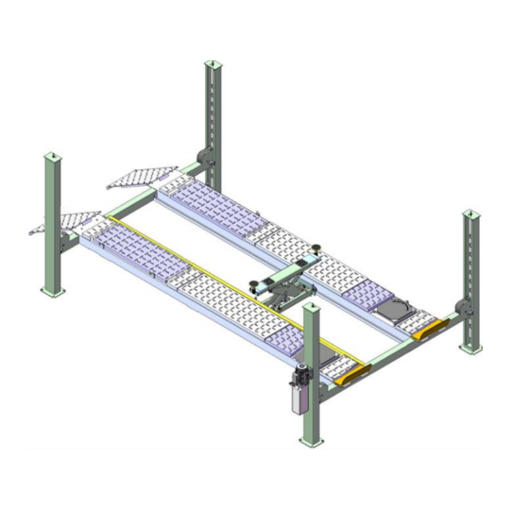
- Page 1 Original Four-Post Lift Model: PRO-12, PRO-12A, PRO-12AX...
-
Page 2: Table Of Contents
CONTENTS Product Features and Specifications ............. 1 Installation Requirement ..............2 Steps of Installation ................5 Exploded View ................. 23 Test Run ..................32 Operation Instruction ............... 33 Maintenance ................... 33 Trouble Shooting ................36 Lift Disposal..................36... -
Page 3: Product Features And Specifications
· Manual hydraulic power system, cable-drived. · Strengthen and Non-skid diamond platforms. · Adjustable platform and adjustable safety lock ladders. · Optional Jack: With hand pump/Air-operated hydraulic pump/Controlled by power unit. . Optional Turnplate:Alignment model only PRO-12 PRO-12A,PRO-12AX Fig.1 Fig.2 ALIGNMENT MODEL SPECIFICATIONS Width... -
Page 4: Installation Requirement
II. INSTALLATION REQUIREMEN A. TOOLS REQUIRED Rotary Hammer Drill (Φ19) Carpenter’s Chalk Hammer Screw Sets Level Bar Tape Measure (7.5m) English Spanner (12”) Pliers Wrench Set Lock Wrench , 12 , 13 , 14 , 17... - Page 5 B. Equipment storage and installation requirements. The equipment should be stored or installed in a shady, normal temperature, ventilated and dry place. C. The equipment should be unload and transfer by forklift. × √ Fig. 4 D. SPECIFICATIONS OF CONCRETE (See Fig.
-
Page 6: Steps Of Installation
III. STEPS OF INSTALLATION A. Location of installation Check and insure the installation location (concrete, layout, space size etc.) is suitable for lift installation. B. Check the parts before assembly 1. Packaged lift and hydraulic power unit (See Fig. 6) Fig. - Page 7 5. Move aside the parts and check the parts according to the shipment parts list (See Fig. 9). PRO-12 Fig. 9 PRO-12A/PRO-12AX Fig. 10 - 6 -...
- Page 8 6. Open the carton of parts and check the parts according to the parts box list (See Fig. 11) Fig. 11 7. Check the parts of the parts bag according to the parts bag list (See Fig. 12) PRO-12 Parts bag 1 PRO-12A Parts bag 1 Parts bag 2 Fig.
- Page 9 (see Fig. 13). Note: Reserve space before and behind the installation site. Car in Direction Use a carpenter’s chalk line to establish installation layout Fig. 13 Model PRO-12 200-3/4” 126-1/4” 237-1/4” PRO-12A 200-3/4” 126-1/4” 237-1/4”...
- Page 10 D. Install cross beams (See Fig. 14, Fig. 15) Hole towards inside Fig. 14 Fig. 15 - 9 -...
- Page 11 E. Fix the anchor bolts 1. Prepare the anchor bolts (See Fig. 16). Spring washer Washer Fig. 16 2. Using the prescribed rotary hammer drill, and drill all the anchor holes and install the anchor bolts, do not tighten the anchor bolts first (See Fig.
- Page 12 2. Install safety ladders (See Fig. 19). This height should be the same for four safety ladders Safety ladder pass through the hole of the top plate, then tighten the two nuts Fig. 19 G. Put the Cross Beams at the same height (See Fig.
- Page 13 H. Install power-side platform. 1. Put the power-side platform upon the cross beams by forklift or manual, offset the cross beams to the outside till the pulleys of both platforms can set up into the cross beam (See , Install the power-side platform and screw up the bolts Fig.21,22) (See Fig.23) Beams and columns tilt...
- Page 14 I. Assembly offside platform and slider block, check the plumbness of (See Fig. 24) columns with level, adjusting with the shims if not, and then tighten the anchor bolts (See Fig. 25). 3-15 3-16 3-14 Install the slider block C View Using the ratchet spanner with socket to tighten the bolts Fig.
- Page 15 1. Pass through the cables from the platform to the columns according to the number of the cables (See Fig. 26). Fig. 26 ○ ○ ○ ○ Model Cable PRO-12 ” ” ” ” 148-5/8 406-1/2 211-3/4 Length PRO-12A (w/ fitting) 151-1/2”...
- Page 16 2. The cable pass through the cross beam to top plate of columns and be screwed with cable nuts then install the cable limit pin. (See Fig. 27, 28), (See Fig. 29) Cable pass through top Cable pass through plate and be screwed between the big pulley with cable nuts.
- Page 17 3. Illustration for platform cables (See Fig. 30, 31, 32). Limit Slider cable ④ cable ② cable ② cable ④ cable ① cable ③ Fig. 30 cable ④ cable ④ cable ③ cable ② cable ② cable ① Fig. 31 cable ②...
- Page 18 K. Install oil-water separator, manual control air valve and power unit (See Fig. 33). Air inlet Air outlet Air flow of oil water separator The side marking “P” on the air valve is Air Input. direction Fig. 33 air solenoid Air flow of valve - 17 -...
- Page 19 L. Install hydraulic system Note: Oil hoses and oil return pipe connected to oil cylinder must be passed above the cable and cylinder inlet port must swing upward to avoid the oil hose and oil return pipe scratched by cable. Oil and air pipes through the clamp...
- Page 20 M. Install air-line system 1. Connecting front and rear Cross Beam cylinders by using 6*4 black air pipe. (the actual length of air line can be cut by user) ( See Fig.38 2, Cut the 6*4 black air pipe by scissor between two retainers, then connect the air line with T fitting.
- Page 21 4. Connecting Oil-water separator and Manual control air valve using air line (See Fig. 41) Oil-water separator Connecting Oil-water separator and Manual control air valve using black air line 8*6 Manual control air valve Black Air pipe ¢6×¢4 Fig. 41 5.
- Page 22 N. Install Electrical System Connect the power source on the data plate of Motor. Note: 1. For the safety of operators, the power wiring must contact the floor well. 2. Pay attention to the direction of rotations when using 380V, three phase motors. Single phase motor (See Fig.
- Page 23 P. Install drive-in ramp, tire stop plate, platform lock plates,Limit rod (See Fig. 45 Install Tire stop plate Install Drive-in ramp The lock plates are used to prevent the turning & slipping of offside platform, Using Hex bolt M8*20 for the connection Install Limit rod Fig.45...
-
Page 24: Exploded View
IV. EXPLODED VIEW Model: PRO-12 Fig.46 - 23 -... - Page 25 Model : PRO-12A PRO-12AX When installing the turntable, both sides are required a 35mm-high turntable block. Fig.47 - 24 -...
- Page 26 PARTS LIST FOR PRO-12, PRO-12A, PRO-12AX Item Part# Description PRO-12 PRO-12A PRO-12AX 11420011A Power-side Column 11420002 Offside Column 10420253 Cross Beam Assy. 10480040 Cross Beam Assy. 10440041 Slider block 10209059 Anchor Bolt 3/4*5-1/2 11410022 Safety Ladder 10420175A Hex Nut M20...
- Page 27 Item Part# Description PRO-12 PRO-12A PRO-12AX 11610667 Drive-in Ramp pulley pin 10209010 Snap ring φ10 10420156 Protecting Ring φ24 10420045 Washer φ6 11420004 Pin for Drive-in Ramp 10420005 Fixing Bolt M5*8 10440501 Part box 10450501 11420031-1 Tire stop plate 10201005 Split pin φ4*50...
- Page 28 Item Part# Description PRO-12 PRO-12A PRO-12AX 10420241 Straight Fitting for Air Line Oil Return Hose 10420195A φ6*φ4*6200mm black 10420131B Black Air Line φ6*φ4 black 10420167A Black Air Line 11476635 Pulley 10476024 Pulley washer φ90*φ51*2 1040101 Turnplate 11430004 Cover for Turnplate...
- Page 29 Parts list for Cross Beam Item Part# Description Note 11420254 Cross Beam for PRO-12(A) 11480023 Cross Beam for PRO-12AX 10420051B Pulley Safety Cover 10209009 Cap Head Bolt M6*8 11420044 Limit Plate 10420138 Socket Bolt M6*16 11420038 Pin φ16 10420037 Snap Ring φ16...
- Page 30 2. CYLINDERS (10420012) Fig. 49 Parts list for Cylinder Item Part# Description Note 51-1 10420059 Dust Ring 51-2 10420060 Y- Ring IDI 51-3 11420061 Head Cap 51-4 10420062 O- Ring 51-5 11420063 Bore Weldment 51-6 11420064 Piston Rod 51-7 11420065 51-8 10420066 Support Ring...
- Page 31 3. Power unit(071102)exploded view: 220V/60HZ, Single Phase Fig.50 - 30 -...
- Page 32 Parts list for 220V/60Hz, Single Phase Item Part# Description 81400180 Rubber Pad 81400130 Starting capacitor 81400088 Running capacitor 10420148 Cap Head Bolt with washer 81400066 Cover of Motor Terminal Box 81400363 Motor Connecting Shaft 090106 Manifold block Washer 10209149 Iron plug 81400276 Red rubber plug 81400259...
- Page 33 4. Illustration of hydraulic valve for power unit return port Relief Release valve valve Check valve Throttle valve Handle for outlet relief valve port Fig.51 - 32 -...
-
Page 34: Test Run
V. TEST RUN Fill the reservoir with approximately 14L Hydraulic Oil (Note: In consideration of Power Unit’s durability,please use Hydraulic Oil 46#). Press button UP the cables will be strained. Check whether the cables match the pulley. Make sure the cables are not across and remove from the pulley. 3. -
Page 35: Operation Instruction
VI. OPERATION INSTRUCTIONS To lift vehicle 1. Keep clean of environment near the lift; 2. Drive vehicle to the Platform and put on the brake; 3. Turn on the power and press the button UP, raise the lift to the working position; Note: make sure the vehicle is steady when the lift is raised. -
Page 36: Maintenance
Oil cylinder maintenance: In order to extend the service life of the oil cylinder, please operate according to the following requirements. 1. Recommend to use N46 anti-wear hydraulic oil. 2. The hydraulic oil of the lifts should be replaced regularly during using. Replace the hydraulic oil 3 months after the first installation, Replace the hydraulic oil once a year afterwards. -
Page 37: Trouble Shooting
VIII. TROUBLE SHOOTING TROUBLE CAUSE REMEDY 1. Start Button does not work 1.Replace Start button 2.Wiring connections are not in good 2.Repair all wiring connections condition 3.Repair or replace motor Motor does 3. Motor burned out 4.Replace AC contactor not run 4. - Page 38 AMGO HYDRAULIC CORPORATION 1931 Jo Rogers Blvd, Manning, South Carolina, USA Tel: (803) 505-6410 Fax: (803) 505-6410 Manual Part No.: 72247703 Revision Date: 2021/05 - 37 -...
Need help?
Do you have a question about the PRO-12 and is the answer not in the manual?
Questions and answers