
Subscribe to Our Youtube Channel
Related Manuals for Wren Robe


Summary of Contents for Wren Robe
- Page 1 ROBE UNIT 1-2 Door Robe / Combi Robe Assembly Guide Robe Combi Robe For Internal Use: FI.WR.INS.132_2100_590_Robe_AssemblyGuide_Rev2...
- Page 2 ROBE UNIT 1-2 Door Robe / Combi Robe Assembly Guide BEFORE YOU START THIS PRODUCT MUST BE SECURED TO THE WALL INSTALLATION SHOULD BE PERFORMED BY A COMPETENT PERSON ONLY. THIS PRODUCT COULD BE DANGEROUS IF INCORRECTLY INSTALLED Hex Key NOT to be used with CAM DOWEL &...
- Page 3 Secure Robe To Wall & Adjacent Units 17-18 Internal Layout Options Hanging Rail Locations 20-21 Internal Drawer Installation 22-23 Sliding Robe - Internal Drawer / Storage Installation Combi Robe Secure Unit To Wall Hinge Adjustment Loose Shelf Fitting For Internal Use: FI.WR.INS.132_2100_590_Robe_AssemblyGuide_Rev2...
- Page 4 ROBE UNIT 1-2 Door Robe / Combi Robe Assembly Guide Back Panel End Panels Bottom Fixed Shelf Top Fixed Shelf Rails Loose Shelf Pack (Cb) (Ct) (Inc Fixings) RAILS PROVIDED WITH THIS UNIT MAY DIFFER IN COLOUR TO THE REST OF THE UNIT See Pages 17-18 for hanging rail / loose shelf layouts For Internal Use: FI.WR.INS.132_2100_590_Robe_AssemblyGuide_Rev2...
- Page 5 ROBE UNIT 1-2 Door Robe / Combi Robe Assembly Guide (F) x20 (KK) x4 (L) x28 (K) x12 (W) x12 (H) x12 Wooden 13mm 15mm 30mm Cam Dowel Cam Lock Dowel Screw Screw Screw (N) x6 (LL) x5 (T) x16...
- Page 6 ROBE UNIT 1-2 Door Robe / Combi Robe Assembly Guide Step 1. Seat dowels (F) into holes in both end panels (B) as shown. For Internal Use: FI.WR.INS.132_2100_590_Robe_AssemblyGuide_Rev2 Page 6...
- Page 7 ROBE UNIT 1-2 Door Robe / Combi Robe Assembly Guide Step 2. Seat cam dowels (W) into holes in both end panels (B) as shown. Do not use power tools with cam dowel (W) or cam lock (H) For Internal Use: FI.WR.INS.132_2100_590_Robe_AssemblyGuide_Rev2...
- Page 8 ROBE UNIT 1-2 Door Robe / Combi Robe Assembly Guide Step 3. Attach panels (Ct), (Cb) & (D) to panels (B), using cam dowels (W), and dowels (F) in positions as shown. All cam locks (H) are to be positioned facing the outside of the unit, for ease of tightening.
- Page 9 ROBE UNIT 1-2 Door Robe / Combi Robe Assembly Guide Step 4. Insert cam locks (H). Do NOT tighten until Step 6. For Internal Use: FI.WR.INS.132_2100_590_Robe_AssemblyGuide_Rev2 Page 9...
- Page 10 ROBE UNIT 1-2 Door Robe / Combi Robe Assembly Guide Step 5. Trim the edgeband covering the groove on the bottom of the end panels. Slide back panel (A) into groove of end panels (B). Once back panel (A) is in position, ensure the panel is flush & square with bottom of end panels (B).
- Page 11 ROBE UNIT 1-2 Door Robe / Combi Robe Assembly Guide Step 6. Hand tighten all cam locks (H), this will tighten the unit together. Do not use power tools with cam dowel (W) or cam lock (H) Step 7. Ensure unit is square. Secure back panel (A) with 15mm screws (L) equally spaced at the top and bottom of back panel (A) into the fixed shelves (Ct) and (Cb) as shown.
- Page 12 ROBE UNIT 1-2 Door Robe / Combi Robe Assembly Guide Step 8. Secure back panel using 16 x back panel clips (T). Slide the back panel clips (T) into the groove of both end panels (B). The back panel clips (T) should be evenly spaced as shown. Once in place, tighten screw.
- Page 13 Lift the unit upright. Once in situ level accordingly, using an 8mm hex key from inside the robe. Attach leg packers to one side of the robe to level the robe on uneven surfaces. Cover leg holes with 15mm cover caps (LL).
- Page 14 98mm It is important to lift unit onto its legs. Do not tilt as depicted in image. Step 10. Lift the robe upright. Once in situ level accordingly. Cover leg holes with 15mm cover caps (LL). For Internal Use: FI.WR.INS.132_2100_590_Robe_AssemblyGuide_Rev2...
- Page 15 ROBE UNIT 1-2 Door Robe / Combi Robe Assembly Guide Step 11. (Where Required) Attach hinge plates onto end panels (B) to suit as shown using 2 screws already in hinge plates. Hinge side to be mounted in accordance to customer specific bedroom plan.
- Page 16 Screw through the pilot holes into the wall, place cover stickers on the heads to conceal them. If unable to use the rails (D) to secure the robe to the wall use the anti tipping brackets provided. Attach the brackets to the top of the robe using 15mm screws (L) provided.
- Page 17 ROBE UNIT 1-2 Door Robe / Combi Robe Assembly Guide ROBE INTERNAL LAYOUT OPTIONS 1. 1-2 Door, 1 Shelf and 1 Rail 5. 1-2 Door, 1 Rail, 2 Internal Drawers 2. 1-2 Door, 1 Shelf and 2 Rails 6. 1-2 Door, 4 Shelves, 2 Internal Drawers 3.
- Page 18 13. Sliding Door Robe -1 Rail, 2, 3, 4 or 5 Internal Drawers, Shoe / Storage Rack 14. Sliding Door Robe - 4 Shelves, 2, 3, 4 or 5 Internal Drawers, Shoe / Storage Rack COMBI ROBE INTERNAL LAYOUT OPTIONS 15.
- Page 19 ROBE UNIT 1-2 Door Robe / Combi Robe Assembly Guide Hanging Rails. Attach hanging rail plates onto end panels (B) as shown using 2 x 15mm screws (L) provided per hanging rail plate. Using the measurements below screw the hanging rail plate onto the end panel using the top hole.
- Page 20 Ensure d ecor end panels are installed before fitting internal drawer unit. Internal Drawers. A. Insert the internal drawer unit into the robe unit. Align the back of the drawers with the back of the robe unit, ensuring the drawer unit is centred inside the robe unit.
- Page 21 C. Screw through drawer end panel, into the filler panel using 2 x 30mm screws (K). Repeat on opposite side. D. Screw down through the drawer unit fixed shelf into the Robe fixed shelf using 4 x 30mm screws (K).
- Page 22 Internal Drawers & Storage. A. Insert the internal drawer unit into the robe unit. Align the back of the drawers with the back of the robe unit, position the unit against the left or right of the unit. (Away from where the sliding doors overlap) B.
- Page 23 1-2 Door Robe / Combi Robe Assembly Guide C. Secure the storage unit to the robe unit with 2 x 30mm screws (K) by screwing through the end panel into robe end panel. Lift the loose shelves and screw in-line with where the shelf sits to conceal the screw head.
- Page 24 Secure chest to the wall by screwing through the pilot holes into the wall. B. Position the combi robe top section on top of the chest. Align the robe and chest sections so the sides and front are straight and flush. Screw up through the chest units top fixed shelf into the robes bottom fixed shelf using 4 x 30mm screws (K).
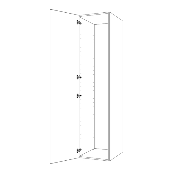
- Page 25 ROBE UNIT 1-2 Door Robe / Combi Robe Assembly Guide Hinge Attachment and Adjustment Step 1. Insert hinges into frontal hinge holes provided, secure hinges with the 2 x screws and hinge dowels already located in the hinges. Hinge dowels Step 2.
- Page 26 ROBE UNIT 1-2 Door Robe / Combi Robe Assembly Guide Loose Shelves Secure shelf peg (JJ) to end panels (B) using 1 x 13mm screw (KK) per shelf peg. 4 x shelf pegs (JJ) are required per loose shelf. Shelf Peg Position loose shelf onto shelf pegs (JJ) ensuring the spikes on the shelf pegs locate in the holes on the bottom of the loose shelf.
- Page 27 ROBE UNIT 1-2 Door Robe / Combi Robe Assembly Guide For Internal Use: FI.WR.INS.132_2100_590_Robe_AssemblyGuide_Rev2 Page 27...
Need help?
Do you have a question about the Robe and is the answer not in the manual?
Questions and answers