
Related Manuals for Wren INFRAMED KITCHEN


Summary of Contents for Wren INFRAMED KITCHEN
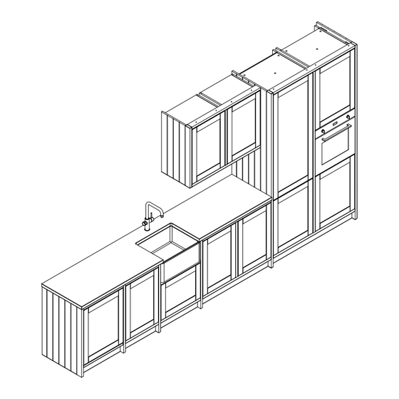
- Page 1 INFRAMED KITCHEN Inf ramed kitchen Assembly Guide Sample Unit Configuration Shown for Illustration Purposes. Page 1 For Internal Use: WKIN00289_Inframed_Kitchen_Guide_Rev3...
- Page 2 INFRAMED KITCHEN Inf ramed kitchen Assembly Guide BEFORE YOU START INSTALLATION SHOULD BE PERFORMED BY A COMPETENT PERSON ONLY. THIS PRODUCT COULD BE DANGEROUS IF INCORRECTLY INSTALLED Page 2 For Internal Use: WKIN00289_Inframed_Kitchen_Guide_Rev3...
- Page 3 INFRAMED KITCHEN Inf ramed kitchen Assembly Guide CONTENTS 5 - 12 Base Unit 13 - 20 Tower Unit 21 - 28 Wall Unit 29 - 31 Belfast Sink Unit 32 - 40 End - Run Dishwasher 41 - 46 Mid - Run Dishwasher...
- Page 4 INFRAMED KITCHEN Inf ramed kitchen Assembly Guide Page 4 For Internal Use: WKIN00289_Inframed_Kitchen_Guide_Rev3...
- Page 5 BASE UNIT Inf ramed kitchen Base Guide Step 1. Set height of the legs to 140mm and attach to the unit. Step 2. Using 2 x 40mm screws, attach 70 x 30mm rail to the end of the unit. (Trim top of rail to adjust height if required) Ensure rail is positioned door thickness + 2 mm forward from the front of the unit.
- Page 6 BASE UNIT Inf ramed kitchen Base Guide Step 3. Cut decor panel to size. Height of the decor end panel will be the height of the unit including legs + 30 and will be the same height as the end rails. (This step is not required if a built in dishwasher is at this side of the unit - See Customer Specific Kitchen Plan for details) Step 4.
- Page 7 BASE UNIT Inf ramed kitchen Base Guide Step 5. Attach Decor panel to the end of the unit. Use 4 x 40mm appropriately positioned countersunk screws, from the inside of the unit. (This step is not required if a built in dishwasher is at this side of the unit - See Customer Specific Kitchen Plan for details) Cover screw heads with cover caps.
- Page 8 BASE UNIT Inf ramed kitchen Base Guide Step 6. Refer to Customer Specific Kitchen plan for unit layout and frame configuration. Step 7. Using 2 x 40mm screws, attach 70 x 30mm rail to the end of the unit. Ensure rail is positioned door thickness + 2mm forward from the front of the unit. Cover screw heads with cover caps.
- Page 9 BASE UNIT Inf ramed kitchen Base Guide Step 8. Attach additional units as required (See step 7). Refer to Customer Specific Kitchen Plan for details. Make sure that the units are aligned and that the rail overhangs the unit the same amount as previous units.
- Page 10 BASE UNIT Inf ramed kitchen Base Guide Step 9. At the end of the run, repeat steps 3 - 6 to attach decor end panel. See Customer Specific Kitchen Plan. If the end of the run is attached to a tower unit, then no end rail or decor end panel are required.
- Page 11 BASE UNIT Inf ramed kitchen Base Guide Step 10. Cut the rear unwrapped profile to the external length between the decor end panels. Step 11. Cut the front top and bottom wrapped rails to the internal length between the end rails. Step 12.
- Page 12 BASE UNIT Inf ramed kitchen Base Guide Step 13. Using 2 x 40mm countersunk screws per unit, attach the top and bottom front rails to the top front rail and bottom fixed shelf on the unit. Make sure that the front of the rails sit 0.5mm back from the front of the side rails and is evenly spaced from the front of the unit along the entire length.
- Page 13 TOWER UNIT Inf ramed kitchen Tower Guide Step 1. Set height of the legs to 140mm and attach to the unit. Step 2. Using 4 x 40mm screws, attach 70 x 30mm rail to the end of the unit. Ensure rail is positioned door thickness + 2 mm forward from the front of the unit.
- Page 14 TOWER UNIT Inf ramed kitchen Tower Guide Step 3. Cut decor panel to size. Height of the decor end panel will be the height of the unit including legs + 30 and will be the same height as the end rails. Step 4.
- Page 15 TOWER UNIT Inf ramed kitchen Tower Guide Step 5. Attach Decor panel to the end of the unit. Use 4 x 40mm appropriately positioned countersunk screws, from the inside of the unit. Cover screw heads with cover caps. Page 15 For Internal Use: WKIN00289_Inframed_Kitchen_Guide_Rev3...
- Page 16 TOWER UNIT Inf ramed kitchen Tower Guide Step 6. Refer to Customer Specific Kitchen plan for unit layout and frame configuration. Step 7. Using 4 x 40mm screws, attach 70 x 30mm rail to the end of the unit. Ensure rail is positioned door thickness + 2mm forward from the front of the unit. Cover screw heads with cover caps.
- Page 17 TOWER UNIT Inf ramed kitchen Tower Guide Step 8. Attach additional units as required (See step 9). Refer to Customer Specific Kitchen Plan for details. Make sure that the units are aligned and that the rail overhangs the unit the same amount as previous units. Page 17 For Internal Use: WKIN00289_Inframed_Kitchen_Guide_Rev3...
- Page 18 TOWER UNIT Inf ramed kitchen Tower Guide Step 9. At the end of the run, repeat steps 3 - 5 to attach decor end panel. See Customer Specific Kitchen Plan. If the end of the run is attached to a tower unit, then no end rail or decor end panel are required. (See image on front page for reference.) Page 18 For Internal Use: WKIN00289_Inframed_Kitchen_Guide_Rev3...
- Page 19 TOWER UNIT Inf ramed kitchen Tower Guide Step 10. Cut the front top and bottom wrapped rail to the internal length between the end rails. Step 11. Cut the bottom rail to reduce the depth to 60mm along the full length as to not clash with the legs. 60mm Page 19 For Internal Use: WKIN00289_Inframed_Kitchen_Guide_Rev3...
- Page 20 TOWER UNIT Inf ramed kitchen Tower Guide Step 12. Using 2 x 40mm countersunk screws per unit, attach the top and bottom front rails to the top and bottom fixed shelves on the unit. Make sure that the front of the rails sit 0.5mm back from the front of the side rails and is evenly spaced from the front of the unit along the entire length.
- Page 21 WALL UNIT Inf ramed kitchen Wall Unit Guide Step 1. Position the rail door thickness + 2 mm forward from the front of the unit. The rail is 60mm larger than the height of the unit. Step 2. Using 2 x 40mm screws, attach 70 x 30mm rail to the end of the unit. Cover screw heads with cover caps.
- Page 22 WALL UNIT Inf ramed kitchen Wall Unit Guide Step 3. Cut decor panel to size. (Cut top edge of the decor). Height of the decor end panel will be the height of the unit + 60mm and will be the same height as the end rails. Step 4.
- Page 23 WALL UNIT Inf ramed kitchen Wall Unit Guide Step 5. Attach Decor end panel to the end of the unit. Use 4 x 40mm appropriately positioned countersunk screws, from the inside of the unit. Cover screw heads with cover caps. For Internal Use: WKIN00289_ Inframed_Kitchen_Guide_Rev3 Page 23...
- Page 24 WALL UNIT Inf ramed kitchen Wall Unit Guide Step 6. Refer to Customer Specific Kitchen plan for unit layout and frame configuration. Step 7. Using 2 x 40mm screws, attach 70 x 30mm rail to the end of the unit. Ensure rail is positioned door thickness + 1.5 mm forward from the front of the unit.
- Page 25 WALL UNIT Inf ramed kitchen Wall Unit Guide Step 8. Attach additional units as required (See step 7). Refer to Customer Specific Kitchen Plan for details. Make sure that the units are aligned and that the rail overhangs the unit the same amount as previous units. For Internal Use: WKIN00289_ Inframed_Kitchen_Guide_Rev3 Page 25...
- Page 26 WALL UNIT Inf ramed kitchen Wall Unit Guide Step 9. At the end of the run, repeat steps 3 - 5 to attach decor end panel. See Customer Specific Kitchen Plan. If the end of the run is attached to a tower unit, then no end rail or decor end panel are required. (See image on front page for reference.) Page 26 For Internal Use: WKIN00289_Inframed_Kitchen_Guide_Rev3...
- Page 27 WALL UNIT Inf ramed kitchen Wall Unit Guide Step 10. Cut the front top and bottom wrapped rails to the internal length between the end rails. For Internal Use: WKIN00289_ Inframed_Kitchen_Guide_Rev3 Page 27...
- Page 28 WALL UNIT Inf ramed kitchen Wall Unit Guide Step 11. Using 2 x 40mm countersunk screws per unit, attach the top and bottom front rails to the top and bottom fixed shelf on the unit. Make sure that the front of the rails sit 0.5mm back from the front of the side rails and is evenly spaced from the front of the unit along the entire length.
- Page 29 BASE UNIT Inf ramed kitchen Belfast Sink Guide Step 1. Cut the rear wrapped rail to the internal length between the adjoining units. Step 2. Cut the front top and bottom wrapped rail to the internal length between the adjoining units Page 29 For Internal Use: WKIN00289_Inframed_Kitchen_Guide_Rev3...
- Page 30 BASE UNIT Inf ramed kitchen Belfast Sink Guide Step 3. Using 3 x 40mm countersunk screws per unit, attach the top front rail to the front rail on the unit. Make sure that the front of the rail is positioned door thickness + 1.5mm forward from the front of the unit and is evenly spaced from the front of the unit along the entire length.
- Page 31 BASE UNIT Inf ramed kitchen Belfast Sink Guide Step 5. Using 2 x 40mm countersunk screws, attach the bottom front rail to the bottom of the base fixed shelf. Make sure that the front of the rail is positioned door thickness + 1.5mm forward from the front of the unit and is evenly spaced from the front of the unit along the entire length.
- Page 32 BASE UNIT Inf ramed kitchen End-Run Dishwasher Guide Step 1. Measure and cut 2 x front wrapped rails to the width of the dishwasher frontal + 4mm. E.g. Rail length for a 596 width dishwasher door = 600mm (Fig.1) (Fig.1) (Fig.2) Step 2.
- Page 33 BASE UNIT Inf ramed kitchen End-Run Dishwasher Guide Step 3. Using one of the cut lengths of wrapped rail, mark the required location on the floor for the front vertical rail at the end of the run of units. Make sure that the front of the end vertical rail is aligned with the rest of the vertical rails on the run of units. Step 4.
- Page 34 BASE UNIT Inf ramed kitchen End-Run Dishwasher Guide Step 5. Using a pocket hole drill, drill the inside face of the end panel that will be at the front of the unit in 4 equally spaced locations. I D E I N S Step 6.
- Page 35 BASE UNIT Inf ramed kitchen End-Run Dishwasher Guide Step 7. Attach 2 x Large L brackets on the inside face of the decor end panel where the panel meets the floor using 2 x 15mm screws each. I D E I N S Step 8.
- Page 36 BASE UNIT Inf ramed kitchen End-Run Dishwasher Guide Step 9. Using appropriate fixings attach the L brackets attached to the decor end panel to the floor and wall. Screws for attaching to the floor and wall are not supplied as these vary depending on material and construction of these surfaces.
- Page 37 BASE UNIT Inf ramed kitchen End-Run Dishwasher Guide Step 11. Pilot drill then, using 4 x 45mm screws, screw the front wrapped rail to the drilled front wrapped rail, offsetting the fronts of the rails by 30mm. Make sure that the rails are aligned and flush at the ends. 30mm Step 12.
- Page 38 BASE UNIT Inf ramed kitchen End-Run Dishwasher Guide Step 13. Using 2 x 30mm pan head screws at each end, attach the front wrapped rail construction to the vertical end rails. Set back the front of the top wrapped rail by 0.5mm. Step 14.
- Page 39 BASE UNIT Inf ramed kitchen End-Run Dishwasher Guide Step 15. Using 2 x 15mm screws per L bracket fix the unwrapped rail construction to the end panel of the adjoining unit and the inside face of the decor end panel. Page 39 For Internal Use: WKIN00289_Inframed_Kitchen_Guide_Rev3...
- Page 40 BASE UNIT Inf ramed kitchen End-Run Dishwasher Guide Step 16. Using 4 x 15mm screws per connecting plate (x2), fix the 30mm rail to the dishwasher frontal, make sure a 2mm gap is maintained. D I S Page 40 For Internal Use: WKIN00289_Inframed_Kitchen_Guide_Rev3...
- Page 41 BASE UNIT Inf ramed kitchen Mid-Run Dishwasher Guide Step 1. Measure and cut 2 x front wrapped rails to the width of the dishwasher frontal + 4mm. E.g. Rail length for a 596 width dishwasher frontal = 600mm (Fig.1) (Fig.1) (Fig.2) Step 2.
- Page 42 BASE UNIT Inf ramed kitchen Mid-Run Dishwasher Guide Step 3. Using a pocket hole drill, drill 2 holes at both ends of one of the top wrapped rails. Step 4. Pilot drill then, using 4 x 45mm screws, screw the front wrapped rail to the drilled front wrapped rail, offsetting the fronts of the rails by 30mm.
- Page 43 BASE UNIT Inf ramed kitchen Mid-Run Dishwasher Guide Step 5. Repeat step 11 for the rear unwrapped rails. 30mm Step 6. Using 2 x 15mm screws per L bracket attach 2 x Large L Brackets at both ends of the unwrapped rail construction.
- Page 44 BASE UNIT Inf ramed kitchen Mid-Run Dishwasher Guide Step 7. Using 2 x 30mm panhead screws at both ends, attach the front wrapped rail construction to the vertical end rails. Set back the front of the top wrapped rail by 0.5mm. Page 44 For Internal Use: WKIN00289_Inframed_Kitchen_Guide_Rev3...
- Page 45 BASE UNIT Inf ramed kitchen Mid-Run Dishwasher Guide Step 8. Using 2 x 15mm screws per L bracket fix the unwrapped rail construction to the end panel of the adjoining unit and the inside face of the decor end panel. Page 45 For Internal Use: WKIN00289_Inframed_Kitchen_Guide_Rev3...
- Page 46 BASE UNIT Inf ramed kitchen Mid-Run Dishwasher Guide Step 9. Using 4 x 15mm screws per connecting plate (x2), fix the 30mm rail to the dishwasher frontal, make sure a 2mm gap is maintained. D I S Page 46 For Internal Use: WKIN00289_Inframed_Kitchen_Guide_Rev3...
- Page 47 INFRAMED KITCHEN Inf ramed kitchen Assembly Guide Prior to quartz installation, cross supports MUST be fitted front to back either side of the hob and sink cutouts, front and back battens must also be notched accordingly. Page 47 For Internal Use: WKIN00289_Inframed_Kitchen_Guide_Rev3...
- Page 48 INFRAMED KITCHEN Inf ramed kitchen Assembly Guide Page 48 For Internal Use: WKIN00289_Inframed_Kitchen_Guide_Rev3...
Need help?
Do you have a question about the INFRAMED KITCHEN and is the answer not in the manual?
Questions and answers