
Related Manuals for ADLINK Technology COM Express DB30 x86


Summary of Contents for ADLINK Technology COM Express DB30 x86
- Page 1 Express-RLP User’s Guide PICMG COM.0 R3.1 DB30 x86 User’s Guide Revision: Rev. 0.2 Date: 2023-07-13 Part Number: 50M-79013-1000 Page 1 Copyright © 2023 ADLINK Technology, Inc.
-
Page 2: Revision History
DB30 x86 User’s Guide PICMG COM.0 R3.0 Revision History Revision Description Date Author Preliminary release 2023-07-12 Debug board drawing label updated 2023-07-13 Page 1 copyright © 2023 ADLINK Technology Inc. -
Page 3: Preface
Product names mentioned herein are used for identification purposes only and may be trademarks / registered trademarks of respective companies. Copyright © 2023 ADLINK Technology Incorporated This document contains proprietary information protected by copyright. All rights are reserved. No part of this manual may be reproduced by any mechanical, electronic, or other means in any form without prior written permission of the manufacturer. - Page 4 Only install/attach and operate equipment on stable surfaces and/or recommended mountings; • If the equipment will not be used for long periods of time, turn off the power source and unplug the equipment. • Page 3 copyright © 2023 ADLINK Technology Inc.
- Page 5 Caution: This information indicates the possibility of minor physical injury, component damage, data loss, and/or program corruption. Warning: This information warns of possible serious physical injury, component damage, data loss, and/or program corruption. Page 4 copyright © 2023 ADLINK Technology Inc.
- Page 6 ADLINK Technology GmbH Hans-Thoma-Strasse 11, D-68163 Mannheim, Germany Tel: +49-621-43214-0 Fax: +49-621 43214-30 Email: emea@adlinktech.com Please visit the Contact page at www.adlinktech.com for information on how to contact the ADLINK regional office nearest you. Page 5 copyright © 2023 ADLINK Technology Inc.
-
Page 7: Table Of Contents
4. Buttons and Switches ..........................................................4 Buttons ....................................................................4 Switch ....................................................................4 5. Port 80 and LEDs ............................................................5 Port 80 Display ................................................................5 LED Indicators ................................................................. 5 EC Status LED .................................................................. 6 Page 6 copyright © 2023 ADLINK Technology Inc. - Page 8 DB30 x86 User’s Guide PICMG COM.0 R3.0 List of Figures Figure 1 Block diagram ..........................................................9 Figure 2 Debug board drawing ......................................................... 10 Figure 3 Debug board and its cables ..................................................... 11 Page 7 copyright © 2023 ADLINK Technology Inc.
-
Page 9: Introduction
Port 80 Decoding Interface with hexadecimal LED display for Power on and Self-test (POST) via I C interface Caution: The DB30 x86 Debug board can only be used on products that have the appropriate FFC debug connector for this usage. Page 8 copyright © 2023 ADLINK Technology Inc. -
Page 10: Specifications
DB30 x86 User’s Guide PICMG COM.0 R3.0 2. Specifications 2.1 Basic Size: 81.6 x 66.8 x 1.6 mm (WxHxD) Operating temperature: 0°C to 60°C Ordering number: 91-79013-0010 2.2 Block Diagram Figure 1 Block diagram Page 9 copyright © 2023 ADLINK Technology Inc. -
Page 11: Drawing
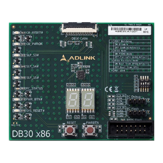
ADLINK Technology Inc. DB30 x86 User’s Guide 2.3 Drawing Figure 2 Debug board drawing Page 10 copyright © 2023 ADLINK Technology Inc. - Page 12 DB30 x86 User’s Guide PICMG COM.0 R3.0 Figure 3 Debug board and its cables Page 11 copyright © 2023 ADLINK Technology Inc.
-
Page 13: Connector Pinouts
Pin # Description Description Pin # Description VCC_SPI_IN SPI_BIOS_CS0# SEL_BIOS SPI_BIOS_MISO BIOS_MODE SPI_BIOS_MOSI DEBUG_PORT_I2C_DATA SPI_BIOS_CLK DEBUG_PORT_I2C_CLK 3V3_EC_A CB_RESET# SPI_BIOS_CS1# EC_FLASH_SMB_DATA POSTWDT_DIS# EC_FLASH_SMB_CLK SUS_S3# PWRBTN# SUS_S4# SYS_RESET# SUS_S5# CB_PWROK EC_WRST# EC_STATUS 3V3_A EC_UART_TX1 EC_UART_RX1 Page 12 copyright © 2023 ADLINK Technology Inc. -
Page 14: Bios 14-Pin Connector
This interface is used to update the SPI BIOS flash located on the COM Express module by using a suitable SPI programmer, e.g. DEDIPROG SF100 Connector type: IDC 14pin, 2.54mm pitch Pin # Description Not connected Not connected SPI_BIOS_CS1# Not connected VCC_SPI SPI_BIOS_CS0# SPI_BIOS_CLOCK SPI_BIOS_MISO SPI_BIOS_MOSI Not connected Not connected Not connected Not connected Page 2 copyright © 2023 ADLINK Technology Inc. -
Page 15: Ec 4-Pin Header
3.3 EC 4-pin Header This interface is used to update the Embedded Controller (EC) located on the COM Express module by using a suitable programmer Connector type: 2.54mm pitch Pin # Description 3V3_EC_A EC_FLASH_SMB_CLK EC_FLASH_SMB_DATA Page 3 copyright © 2023 ADLINK Technology Inc. -
Page 16: Buttons And Switches
ON = Disable OFF = Enable (default) BIOS MODE ON = PICMG MODE OFF = FAILSAFE MODE (default) BIOS FAILSAFE MODE ON = Boot from SPI0 (default) OFF = Boot from SPI1 NOT USED Page 4 copyright © 2023 ADLINK Technology Inc. -
Page 17: Port 80 And Leds
LED will show the status of the BMC on the COM Express module PWR_BTN# LED will lit on active power button signal for COM Express module SYS_RESET# LED will lit on active reset signal for COM Express module Page 5 copyright © 2023 ADLINK Technology Inc. -
Page 18: Ec Status Led
Fast blinking status LED If and when the board is running on Fail-Safe-BIOS, the Status LED will be blinking extremely fast until addressed.g Short bright blue flashes System is in Suspend-to=RAM. every 4s Page 6 copyright © 2023 ADLINK Technology Inc. - Page 19 LED Error code message Exception Code Error Message NOERROR NO_SUSCLK NO_SLP_S5 NO_SLP_S4 NO_SLP_S3 BIOS_FAIL RESET_FAIL RESETIN_FAIL NO_CB_PWROK CRITICAL_TEMP POWER_FAIL VOLTAGE_FAIL RSMRST_FAIL NO_VDDQ_PG NO_V1P05A_PG NO_VCORE_PG NO_SYS_GD NO_V5SBY NO_V3P3A NO_V5_DUAL NO_PWRSRC_GD NO_P_5V_3V3_S0_PG NO_SAME_CHANNEL NO_PCH_PG Page 7 copyright © 2023 ADLINK Technology Inc.
Need help?
Do you have a question about the COM Express DB30 x86 and is the answer not in the manual?
Questions and answers