
Subscribe to Our Youtube Channel
Related Manuals for ADLINK Technology DAQ-2213


Summary of Contents for ADLINK Technology DAQ-2213
- Page 1 sales@artisantg.com artisantg.com (217) 352-9330 | Visit our website - Click HERE...
- Page 2 DAQ/DAQe-2213/2214 16-ch High Performance Low-Cost Data Acquisition Card User’s Manual Manual Rev. Revision Date: Dec. 29, 2023 Part No: 50M-12267-1000...
-
Page 3: Revision History
Revision History Revision Release Date Description of Change(s) 1.00 2004-02-12 Previous version PN: 50-11034-100 Initial release under new part number. Added 1.4 Software Support. 2023-12-28 Added 2.4 Switch and Jumper Settings. Added 4.1.6 Bus-mastering DMA Data Transfer. - Page 4 DAQ/DAQe-221x Series Preface Copyright © 2023 ADLINK Technology Inc. This document contains proprietary information protected by copy- right. All rights are reserved. No part of this manual may be repro- duced by any mechanical, electronic, or other means in any form without prior written permission of the manufacturer.
-
Page 5: California Proposition 65 Warning
California Proposition 65 Warning WARNING: This product can expose you to chemicals including acrylamide, arsenic, benzene, cadmium, Tris(1,3-dichloro-2-propyl)phosphate (TDCPP), 1,4-Diox- ane, formaldehyde, lead, DEHP, styrene, DINP, BBP, PVC, and vinyl materials, which are known to the State of California to cause cancer, and acrylamide, benzene, cadmium, lead, mercury, phthalates, toluene, DEHP, DIDP, DnHP, DBP, BBP, PVC, and vinyl materials, which are known to the State of California to cause... -
Page 6: Table Of Contents
DAQ/DAQe-221x Series Table of Contents Preface ..................iii List of Tables................. vii List of Figures ................ ix 1 Introduction ................ 1 Features................2 Applications ................. 3 Specifications............... 3 Software Support ..............9 2 Installation ................ 13 Contents of Package ............13 Unpacking ................ - Page 7 5 Calibration ................. 81 Loading Calibration Constants........... 81 Auto-calibration ..............82 Saving Calibration Constants..........82 Important Safety Instructions..........83 Getting Service ..............85...
-
Page 8: List Of Tables
DAQ/DAQe-221x Series List of Tables Table 1-1: Programmabel Input Range..........3 Table 1-2: Bandwidth ................ 4 Table 1-3: System Noise..............4 Table 1-4: CMRR (DC to 60 Hz) ............5 Table 1-5: Settling Time to Full Scale Step........5 Table 2-1: Board ID SW1 DIP Switch Settings ....... 17 Table 3-1: CN1 Pin Assignment for DAQ/DAQe-2213/2214... - Page 9 This page intentionally left blank. viii List of Tables...
-
Page 10: List Of Figures
DAQ/DAQe-221x Series List of Figures Figure 2-1: PCB Layout of DAQ/DAQe-2213/2214..... 15 Figure 2-2: Board ID SW1 DIP Switch ........16 Figure 2-3: Enable Board ID Configuration ......... 18 Figure 2-4: DIO Initial Status (JP4) ..........19 Figure 3-1: Floating Source and RSE Input Connections ... 29 Figure 3-2: Ground-referenced Sources and NRSE Input Connections.............. - Page 11 Figure 4-25: Mode 5 Operation ............. 64 Figure 4-26: Mode 6 Operation ............. 65 Figure 4-27: Mode 7 Operation ............. 66 Figure 4-28: Mode 8 Operation ............. 66 Figure 4-29: Analog Trigger Block Diagram........68 Figure 4-30: Below-Low Analog Trigger Condition ....... 69 Figure 4-31: Above-High Analog Trigger Condition ......
-
Page 12: Introduction
DAQ/DAQe-221x Series Introduction The ADLINK DAQ/DAQe-221x Series is a 16-ch low cost, high- performance multifunction DAQ card that can sample up to 16 analog input channels with different gain settings and scan sequences, making it ideal for dealing with analog signals with various input ranges and sampling speeds. -
Page 13: Features
1.1 Features The DDAQ/DAQe-221x Series Advanced Data Acquisition Card provides the following advanced features: 32-bit PCI-Bus, Plug and Play Up to 16 single-ended inputs or 8 differential inputs, mixing of SE and DI analog input signals is possible 512 word analog input Channel Gain Queue configuration ... -
Page 14: Applications
DAQ/DAQe-221x Series 1.2 Applications Automotive Testing Cable Testing Transient signal measurement Laboratory Automation Biotech measurement 1.3 Specifications Analog Input (AI) Programmable channels: 16 single-ended (SE) or 8 differential input (DI) Mixing of SE and DI analog signal sources (Software ... -
Page 15: Table 1-2: Bandwidth
Data transfers: Programmed I/O Bus-mastering DMA with scatter/gather Channel Gain Queue configuration size: 512 words Bandwidth (Typical 25ºC): Small signal Large signal Input range bandwidth bandwidth (-3dB) (1% THD) ±10 V 0 V to 10 V 760 kHz 280 kHz ±5 V... -
Page 16: Table 1-4: Cmrr (Dc To 60 Hz)
DAQ/DAQe-221x Series CMRR (DC to 60 Hz, Typical) Input Range CMRR Input Range CMRR ±10 V 83 dB 0 V to 10 V 87 dB ±5 V 87 dB 0 V to 5 V 90 dB ±2.5 V 90 dB 0 V to 2.5 V 92 dB ±1.25 V... - Page 17 Analog Output (AO) (for DAQ/DAQe-2214 only) Channels: Two-channel analog voltage output DA converter: LTC7545 or equivalent Max update rate: 1 MS/s Resolution: 12 bits FIFO buffer size: 512 samples per channel when both channels are ...
- Page 18 DAQ/DAQe-221x Series General Purpose Digital I/O (G.P. DIO, 82C55A) Channels: 24 programmable input/output Compatibility: TTL Input voltage: Logic Low: VIL=0.8 V max; IIL=0.2 mA max High: VIH=2.0 V max; IIH=0.02 mA max Output voltage: Low: VOL=0.5 V max;...
- Page 19 External Analog Trigger Input (EXTATRIG) Input Impedance: 20 k Coupling: DC Protection: Continuous ±35 V maximum Digital Trigger (D.Trig) Compatibility: TTL/CMOS Response: Rising or falling edge Pulse Width: 10 ns min System Synchronous Interface (SSI) Trigger lines: 7 ...
-
Page 20: Software Support
DAQ/DAQe-221x Series 1.4 Software Support ADLINK provides versatile software drivers and packages to suit various user approaches to building a system. Aside from pro- gramming libraries, such as DLLs, for most Windows-based sys- tems, ADLINK also provides drivers for other application environments such as LabVIEW. - Page 21 1.4.1 MAPS Core ADLINK MAPS Core is a software package that includes all the device drivers for Windows and a system level management tool called ACE (ADLINK Connection Explorer). With MAPS Core installed, the operating system can identify ADLINK devices and assign the necessary resources for low-level access, such as IO read/write or direct memory access.
- Page 22 DAQ/DAQe-221x Series ADLINK Connection Explorer (ACE) also provides a ready-to-use soft-front panel for digitizer products. Clicking the Launch button in the "Utility" block allows users to control digitizers through the UI and display the acquired waveform/data on the screen. 1.4.2 MAPS/LV, LabVIEW Support Customers who develop their own programs in LabVIEW must install the MAPS/LV software package.
- Page 23 1.4.3 MAPS/C, C & C++ Support Customers who develop their own programs in C or C++ environ- ments must install the MAPS/C software package. MAPS/C includes all the software components required for developing applications in C/C++, such as header files, a device API library and versatile sample programs for understanding how to manipu- late the device correctly.
-
Page 24: Installation
DAQ/DAQe-221x Series Installation This chapter describes how to install the DAQ/DAQe-2213/2214. The contents of the package and unpacking information are out- lined first. 2.1 Contents of Package In addition to this User's Manual, the package includes the follow- ing items: DAQ/DAQe-2213/2214 Low-Cost Data Acquisition Card ... -
Page 25: Unpacking
2.2 Unpacking The DAQ/DAQe-2213/2214 card contains electro-static sensitive components that can be easily damaged by static electricity. Therefore, the card should be handled on a grounded anti-static mat. The operator should be wearing an anti-static wristband, grounded at the same point as the anti-static mat. Inspect the card module carton for obvious damage. -
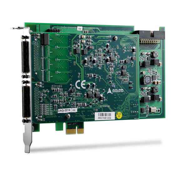
Page 26: Daq/Daqe-2213/2214 Layout
DAQ/DAQe-221x Series 2.3 DAQ/DAQe-2213/2214 Layout Figure 2-1: PCB Layout of DAQ/DAQe-2213/2214... -
Page 27: Switch And Jumper Settings
2.4 Switch and Jumper Settings 2.4.1 Board ID (SW1) The DAQ/DAQe-2213/2214 has a built-in DIP switch (SW1), which is used to define each card’s board ID. When there are multiple cards on the same platform, this board ID switch is useful for iden- tifying each card’s device number. -
Page 28: Table 2-1: Board Id Sw1 Dip Switch Settings
DAQ/DAQe-221x Series Pin 1 Pin 2 Pin 3 Pin 4 Board ID Table 2-1: Board ID SW1 DIP Switch Settings... -
Page 29: Figure 2-3: Enable Board Id Configuration
Board ID configuration is disabled by default. To enable Board ID configuration, install D2K-DASK and launch W2K_D2kUtil.exe in C:\ADLINK\D2K-DASK\Utility\. Select NOTE: NOTE: your Card Type and uncheck Ignore Board ID. See figure below. Figure 2-3: Enable Board ID Configuration... -
Page 30: Figure 2-4: Dio Initial Status (Jp4)
DAQ/DAQe-221x Series 2.4.2 DIO Initial Status (JP4) The default jumper setting is enabled, making the DIO initial status low by using a 1K ohm resistor poll down to GND. To disable this feature, move the jumper cap as shown in the table below. Disabled Enabled Figure 2-4: DIO Initial Status (JP4) -
Page 31: Pci Configuration
2.5 PCI Configuration 2.5.1 Plug and Play With support for plug and play, the card requests an interrupt num- ber via its PCI controller. The system BIOS responds with an inter- rupt assignment based on the card information and on known system parameters. -
Page 32: Signal Connections
DAQ/DAQe-221x Series Signal Connections This chapter describes the connectors of the DAQ/DAQe-2213/ 2214 and the signal connection between the DAQ/DAQe-2213/ 2214 and external devices. 3.1 Connector Pin Assignment DAQ/DAQe-2213/2214 is equipped with two 68-pin VHDCI-type connectors (AMP-787254-1) and one 20-pin ribbon male connec- tor. -
Page 33: Table 3-1: Cn1 Pin Assignment For Daq/Daqe-2213/2214
3.1.1 CN1 Connector AI0 (AIH0) (AIL0) AI32 AI1 (AIH1) (AIL1) AI33 AI2 (AIH2) (AIL2) AI34 AI3 (AIH3) (AIL3) AI35 AI4 (AIH4) (AIL4) AI36 AI5 (AIH5) (AIL5) AI37 AI6 (AIH6) (AIL6) AI38 AI7 (AIH7) (AIL7) AI39 43 NC 44 NC 45 NC 46 NC 47 NC 48 NC... -
Page 34: Table 3-2: Cn2 Pin Assignment For Daq/Daqe-2213
DAQ/DAQe-221x Series 3.1.2 CN2 Connector DGND DGND RESERVED DGND EXTDTRIG DGND SSHOUT DGND RESERVED DGND RESERVED DGND RESERVED DGND AFI0 12 DGND GPTC0_SRC DGND GPTC0_GATE 14 DGND GPTC0_UPDOWN DGND GPTC0_OUT DGND GPTC1_SRC DGND GPTC1_GATE 18 DGND GPTC1_UPDOWN DGND GPTC1_OUT DGND EXTTIMEBASE DGND PB7 22... -
Page 35: Table 3-3: Cn2 Pin Assignment For Daq/Daqe-2214
DA0OUT AOGND DA1OUT AOGND AOEXTREF AOGND DGND DGND EXTWFTRIG DGND EXTDTRIG DGND SSHOUT DGND RESERVED DGND RESERVED DGND AFI1 DGND AFI0 DGND GPTC0_SRC DGND GPTC0_GATE 14 DGND GPTC0_UPDOWN DGND GPTC0_OUT DGND GPTC1_SRC DGND GPTC1_GATE 18 DGND GPTC1_UPDOWN DGND GPTC1_OUT DGND EXTTIMEBASE DGND PC7 26... -
Page 36: Table 3-4: Cn1/Cn2 Signal Description
DAQ/DAQe-221x Series CN1/CN2 Connector Signal Description Signal Name Reference Direction Description Analog ground for AI. All three ground references (AIGND, AIGND — — AOGND, and DGND) are connected together on board. Analog Input Channels 0~16. Each channel pair, AI<i, i+8> (I=0..7) can be configured either AI<0..16/95>... -
Page 37: Table 3-5: Ssi Connector Pin Assignment For Daq/Daqe-2213
Signal Name Reference Direction Description Auxiliary Function Input 0 AFI0 DGND Input (ADCONV, AD_START) Auxiliary Function Input 1 AFI1 DGND Input (DAWR, DA_START) Table 3-4: CN1/CN2 Signal Description 3.1.3 SSI Connector SSI_TIMEBASE DGND SSI_ADCONV DGND RESERVED DGND SSI_SCAN_START DGND RESERVED DGND SSI_AD_TRIG DGND... -
Page 38: Table 3-7: Ssi Connector Legend
DAQ/DAQe-221x Series SSI Connector Signal Description: SSI Timing Signal Setting Function Master Send the TIMEBASE out SSI_TIMEBASE Accept the SSI_TIMEBASE to replace the internal Slave TIMEBASE signal. Master Send the ADCONV out SSI_ADCONV Accept the SSI_ADCONV to replace the internal Slave ADCONV signal. -
Page 39: Analog Input Signal Connection
3.2 Analog Input Signal Connection The DAQ/DAQe-2213/2214 provides up to 16 single-ended or 8 differential analog input channels. Users can fill the Channel Gain Queue to get desired combination of the input signal types. The analog signal can be converted to digital value by the A/D con- verter. -
Page 40: Figure 3-1: Floating Source And Rse Input Connections
DAQ/DAQe-221x Series Referenced Single-ended (RSE) Mode In referenced single-ended mode, all input signals are con- nected to the ground provided by the DAQ/DAQe-2213/2214. This is suitable for connections with floating signal sources. Figure 3-1 shows an illustration. Note that when more than two floating sources are connected, these sources will be refer- enced to the same common ground. -
Page 41: Figure 3-3: Ground-Referenced Source And Differential Input
3.2.3 Differential Input Mode The differential input mode provides two inputs that respond to signal voltage difference between them. If the signal source is ground-referenced, the differential mode can be used for the com- mon-mode noise rejection. Figure 3-3 shows the connection of ground-referenced signal sources under differential input mode. -
Page 42: Operation Theory
DAQ/DAQe-221x Series Operation Theory The operation theory of the DAQ/DAQe-2213/2214 functions are described in this chapter. The functions include the A/D conver- sion, D/A conversion, digital I/O, and general purpose counter/ timer. The operation theory can help you understand how to con- figure and program the DAQ/DAQe-2213/2214. -
Page 43: Table 4-1: Bipolar Analog Input Range And Output Digital Code
4.1.1 DAQ/DAQe-2213/2214 AI Data Format The data format of the acquired 16-bit A/D data is two’s comple- ment coding. Table 4-1and Table 4-2 shows the valid input ranges and the ideal transfer characteristics. Digital Description Bipolar Analog Input Range code Full-scale Range ±10V ±5V... - Page 44 DAQ/DAQe-221x Series 4.1.2 Software Conversion with Polling Data Transfer Acquisition Mode (Software Polling) This is the easiest way to acquire a single A/D data. The A/D con- verter starts one conversion whenever the dedicated software command is executed. Then the software would poll the conver- sion status and read the A/D data back when it is available.
-
Page 45: Programmable Scan Acquisition Mode
4.1.3 Programmable Scan Acquisition Mode Scan Timing and Procedure It is recommended that you use this mode if your applications need a fixed and precise A/D sampling rate. You can accu- rately program the period between conversions of individual channels. There are at least four counters which need to be specified: SI_counter (24-bit): Specify the Scan Interval = SI_counter / ... -
Page 46: Figure 4-1: Scan Timing
DAQ/DAQe-221x Series 3 Scans, 4 Samples per scan (PSC_Counter=3, NumChan_Counter=4) ( channel sequences are specified in Channel Gain Queue) Scan_start AD_conversion Scan_in_progress (SSHOUT)(pin8 on CN2) Acquisition_in_progress Sampling Interval t= Scan Interval T= SI2_COUNTER/TimeBase SI_COUNTER/TimeBase Figure 4-1: Scan Timing There are four trigger modes to start the scan acquisition. Refer to section 4.1 for details. -
Page 47: Specifying Channels, Gains, And Input Configurations In The Channel Gain Queue
Scan with SSH You can send the SSHOUT signal on CN2 to external S&H cir- cuits to sample and hold all signals if you want to simultane- ously sample all channels in a scan, as illustrated in Figure 4-1. The ‘SSHOUT’ signal is sent to external S&H circuits to hold the analog signal. -
Page 48: Trigger Modes
DAQ/DAQe-221x Series 4.1.5 Trigger Modes DAQ/DAQe-2213/2214 provides 3 trigger sources (internal soft- ware, external analog, and digital trigger sources). Only select one of them as the source of the trigger event. A trigger event occurs when the specified condition is detected on the selected trigger source (For example, a rising edge on the external digital trigger input). -
Page 49: Figure 4-3: Pre-Trigger (Trigger With Scan In Progress)
Note that if a trigger event occurs when a scan is in progress, the data acquisition won't stop until the scan completes, and the stored M scans of data includes the last scan. Therefore, the first stored data will always be the first channel entry of a scan (that is, the first channel entry in the Channel Gain Queue if the number of entries in the Channel Gain Queue is equivalent to the value of NumChan_counter), no matter when a trigger signal occurs, as... -
Page 50: Figure 4-4: Pre-Trigger With M_Enable=0 (Trigger Occurs Before M Scans)
DAQ/DAQe-221x Series When the trigger signal occurs before the first M scans of data are converted, the amount of stored data could be fewer than the orig- inally specified amount M_counter, as illustrated in Figure 4-4. This situation can be avoided by setting M_enable. If M_enable is set to 1, the trigger signal will be ignored until the first M scans of data are converted, and it assures the user M scans of data under pre-trigger mode, as illustrated in Figure 4-5. -
Page 51: Figure 4-5: Pre-Trigger With M_Enable=1
(M_counter = M = 3, NumChan_counter=4, PSC_counter=0) The first M scans Trigger signals which occur in the shadow region(the first M scans) will be ignored Trigger Scan_start AD_conversion Scan_in_progress (SSHOUT)(pin2 on CN2) Acquisition_in_progress Aquired data Acquired & stored data (M scans) Operation start Figure 4-5: Pre-trigger with M_enable=1 The PSC_counter is set to 0 in pre-trigger acquisition mode. -
Page 52: Figure 4-6: Middle-Trigger With M_Enable = 1
DAQ/DAQe-221x Series Middle-Trigger Acquisition Use middle-trigger acquisition in applications where you want to collect data before and after a trigger event. The number of scans (M) stored before the trigger is specified by M_counter, while the number of scans (N) after the trigger is specified by PSC_counter. -
Page 53: Figure 4-7: Middle-Trigger (Trigger Occurs When A Scan Is In Progress)
If a trigger event occurs when a scan is in progress, the stored N scans of data would include this scan. The first stored data will always be the first channel entry of a scan, as illustrated in Figure 4-7. Figure 4-7: Middle-Trigger (Trigger occurs when a scan is in progress) -
Page 54: Figure 4-8: Post-Trigger
DAQ/DAQe-221x Series Post-Trigger Acquisition Use post-trigger acquisition in applications where you want to collect data after a trigger event. The number of scans after the trigger is specified in PSC_counter, as illustrated in Figure 4-8. The total acquired data length = NumChan_counter * PSC_counter. -
Page 55: Figure 4-9: Delay Trigger
Delay Trigger Acquisition Use delay trigger acquisition in applications where you want to delay the data collection after the occurrence of a specified trig- ger event. The delay time is controlled by the value, which is pre-loaded in the Delay_counter (16 bits). The counter counts down on the rising edge of the Delay_counter clock source after the trigger condition is met. -
Page 56: Figure 4-10: Post Trigger With Re-Trigger
DAQ/DAQe-221x Series Post-Trigger or Delay-trigger Acquisition with re-trigger Use post-trigger or delay-trigger acquisition with re-trigger function in applications where you want to collect data after several trigger events. The number of scans after each trigger is specified in PSC_counter, and users could program Retrig_no to specify the re-trigger numbers. - Page 57 4.1.6 Bus-mastering DMA Data Transfer In programmable scan acquisition mode, all DAQ/DAQe/PXI series cards supports bus-mastering DMA data transfer. PCI bus- mastering DMA is necessary for high speed DAQ in order to utilize the maximum bus bandwidth. The bus-mastering controller con- trols the PCI bus when it becomes the master.
-
Page 58: Figure 4-11: Linked List Of Pci Address Dma Descriptors
DAQ/DAQe-221x Series support 64-bit addresses which can be mapped into more than 4 GB of the address space. You can allocate many small size mem- ory blocks and chain their associative DMA descriptors altogether by their application programs. Figure 4-11: Linked List of PCI Address DMA Descriptors In non-chaining mode, the maximum DMA data transfer size is 2M double words (8 MB). -
Page 59: D/A Conversion (For Daq/Daqe-2214 Only)
4.2 D/A Conversion (for DAQ/DAQe-2214 only) There are two 12-bit D/A output channels available in the DAQ/ DAQe-2214. When using D/A converters, you should assign and control the D/A converter reference sources for the D/A operation mode and D/A channels. You could also set the output polarity to unipolar or bipolar. -
Page 60: Table 4-4: Unipolar Output Code Table (Vref=10V If Internal Reference Is Selected)
DAQ/DAQe-221x Series Digital Code Analog Output 111111111111 Vref * (4095/4096) 100000000000 Vref * (2048/4096) 000000000001 Vref * (1/4096) 000000000000 Table 4-4: Unipolar Output Code Table (Vref=10V if internal reference is selected) The D/A conversion is initiated by a trigger source. You must decide how to trigger the D/A conversion. - Page 61 4.2.2 Timed Waveform Generation This mode can provide your applications with a precise D/A output with a fixed update rate. It can be used to generate an infinite or finite waveform. You can accurately program the update period of the D/A converters. The D/A output timing is provided through a combination of coun- ters in the FPGA on board.
-
Page 62: Figure 4-12: Typical D/A Timing Of Waveform Generation
DAQ/DAQe-221x Series 4 update counts, 3 iterations (UC _Counter=4, IC_Counter=3) Trigger UC_Counter=4 DAWR WFG_in_progress Delay until Delay until Delay until DLY1_Counter DLY2_Counter DLY2_Counter reaches 0 reaches 0 reaches 0 DA update_interval t= UI_Counter/Timebase Output Waveform Operation start A single waveform IC_Counter = 3 Figure 4-12: Typical D/A Timing of Waveform Generation The maximum D/A update rate is 1MHz. -
Page 63: Figure 4-13: Post Trigger Waveform Generation
4.2.3 Trigger Modes Post-Trigger Generation Use post-trigger when you want to perform DA waveform right after a trigger event occurs. In this trigger mode DLY1_Counter is ignored and not be specified. Figure 4-13 shows a single waveform generated right after a trigger signal is detected and assuming the data in the data buffer are 2V, 4V, 6V, 3V, 0V, -4V, -2V, and 4V. -
Page 64: Figure 4-14: Delay Trigger Waveform Generation
DAQ/DAQe-221x Series Figure 4-14: Delay Trigger Waveform Generation Post-Trigger or Delay-Trigger with Re-trigger Use post-trigger or delay-trigger with re-trigger function when you want to generate waveform after more than one trigger events. The re-trigger function can be enabled or disabled by software setting. -
Page 65: Figure 4-16: Finite Iterative Waveform Generation With Post-Trigger (Dly2_Counter = 0)
Iterative Waveform Generation Set IC_Counter in order to generate iterative waveforms from the data of a single waveform. The counter stores the iteration number and the iterations may be finite (Figure 4-16) or infinite (Figure 4-17). Take note that in infinite mode the waveform generation does not stop until software stop function is exe- cuted and IC_Counter is still valid when stop mode III is selected. -
Page 66: Figure 4-17: Infinite Iterative Waveform Generation With Post-Trigger (Dly2_Counter = 0)
DAQ/DAQe-221x Series Figure 4-17: Infinite Iterative Waveform Generation with Post-trigger (DLY2_Counter = 0) Delay2 in Iterative Waveform Generation To stretch out the flexibility of the D/A waveform generation, we add a DLY2_Counter to separate two consecutive waveforms in iterative waveform generation. The time between two wave- forms is assigned by setting the value of the DLY2_Counter. -
Page 67: Figure 4-18: Stop Mode I
Stop Modes of Scan Update You can call software stop function to stop waveform genera- tion when it is still in progress. Three stop modes are provided for timed waveform generation meant to stop the waveform generation. You can apply these three modes to stop waveform generation no matter infinite or finite waveform generation mode is selected. -
Page 68: Figure 4-19: Stop Mode Ii
DAQ/DAQe-221x Series In stop mode II, after a software stop command is given, the waveform generation does not stop until a complete single waveform is finished. See Figure 4-19. Since the UC_counter is set to four, the total DA update counts (number of pulses of DAWR signal) must be a multiple of four (update counts = 20 in this example). -
Page 69: Digital I/O
4.3 Digital I/O The DAQ/DAQe-2213/2214 contains 24-lines of general-purpose digital I/O (GPIO), which are provided through an 82C55A chip. The 24-lines GPIO are separated into three ports: Port A, Port B, and Port C. Port A, Port B, Port C high nibble (bit-4 to bit-7), and low nibble (bit 0 to bit 3) can be programmed to be input or output individually. -
Page 70: General Purpose Timer/Counter Operation
DAQ/DAQe-221x Series 4.4 General Purpose Timer/Counter Operation Two independent 16-bit up/down timer/counter are designed within FPGA for various applications. They have the following fea- tures: Count up/down controlled by hardware or software Programmable counter clock source (internal or external ... -
Page 71: General Purpose Timer/Counter Modes
4.4.2 General Purpose Timer/Counter modes Eight programmable timer/counter modes are provided. All modes start operating following a software-start signal that is set by the software. The GPTC software reset initializes the status of the counter and re-loads the initial value to the counter. The operation remains halted until the software-start is re-executed. -
Page 72: Figure 4-22: Mode 2 Operation
DAQ/DAQe-221x Series Mode 2: Single Period Measurement In this mode, the counter counts the period of the signal on GPTC_GATE in terms of GPTC_CLK. Initial count can be loaded from software. After the software-start, the counter counts the number of active edges on GPTC_CLK between two active edges of GPTC_GATE. -
Page 73: Figure 4-23: Mode 3 Operation
Mode 3: Single Pulse-width Measurement In this mode, the counter counts the pulse-width of the signal on GPTC_GATE in terms of GPTC_CLK. Initial count can be loaded from software. After the software-start, the counter counts the number of active edges on GPTC_CLK when GPTC_GATE is in its active state. -
Page 74: Figure 4-24: Mode 4 Operation
DAQ/DAQe-221x Series Mode 4: Single Gated Pulse Generation This mode generates a single pulse with programmable delay and programmable pulse-width following the software-start. The two programmable parameters could be specified in terms of periods of the GPTC_CLK input by software. GPTC_GATE is used to enable/disable counting. -
Page 75: Figure 4-25: Mode 5 Operation
Mode 5: Single Triggered Pulse Generation This function generates a single pulse with programmable delay and pro-grammable pulse-width following an active GPTC_GATE edge. You could specify these programmable parameters in terms of periods of the GPTC_CLK input. Once the first GPTC_GATE edge triggers the single pulse, GPTC_GATE takes no effect until the software-start is re-exe- cuted. -
Page 76: Figure 4-26: Mode 6 Operation
DAQ/DAQe-221x Series Mode 6: Re-triggered Single Pulse Generation This mode is similar to Mode 5 except that the counter gener- ates a pulse following every active edge of GPTC_GATE. After the software-start, every active GPTC_GATE edge triggers a single pulse with programmable delay and pulse-width. Any GPTC_GATE triggers that occur when the prior pulse is not completed would be ignored. -
Page 77: Figure 4-27: Mode 7 Operation
Mode 7: Single Triggered Continuous Pulse Generation This mode is similar to Mode 5 except that the counter gener- ates continuous periodic pulses with programmable pulse inter- val and pulse-width following the first active edge of GPTC_GATE. Once the first GPTC_GATE edge triggers the counter, GPTC_GATE takes no effect until the software-start is re-executed. -
Page 78: Trigger Sources
DAQ/DAQe-221x Series 4.5 Trigger Sources ADLINK provides flexible trigger selections in the DAQ/DAQe- 2213/2214. In addition to the internal software trigger, the DAQ/ DAQe-2213/2214 also supports external analog, digital triggers, and SSI triggers. You can configure the trigger source by software for A/D and D/A processes individually. -
Page 79: Table 4-5: Analog Trigger Src1 (Extatrig) Ideal Transfer
Input Multipexer Instrumentation Amplifier Converter n = 0, ...,15 SRC2 Analog Trigger EXTATRIG SRC1 Circuit Figure 4-29: Analog Trigger Block Diagram Trigger level digital setting Trigger voltage 0xFF 9.92V 0xFE 9.84V 0x81 0.08V 0x80 0x7F -0.08V 0x01 -9.92V Table 4-5: Analog Trigger SRC1 (EXTATRIG) Ideal Transfer Characteristic The trigger signal is generated when the analog trigger condition is satisfied. -
Page 80: Figure 4-30: Below-Low Analog Trigger Condition
DAQ/DAQe-221x Series Below-Low Analog Trigger Condition Figure 4-30 shows the below-low analog trigger condition, the trigger signal is generated when the input analog signal is less than the Low_Threshold voltage, and the High_Threshold set- ting is not used in this trigger condition. Figure 4-30: Below-Low Analog Trigger Condition Above-High Analog Trigger Condition Figure 4-31 shows the above-high analog trigger condition, the... -
Page 81: Figure 4-32: Inside-Region Analog Trigger Condition
Inside-Region Analog Trigger Condition Figure 4-32 shows the inside-region analog trigger condition, the trigger signal is generated when the input analog signal level falls in the range between the High_Threshold and the Low_Threshold voltages. Note the High_Threshold setting should be always higher than the Low_Threshold voltage set- ting. -
Page 82: Figure 4-33: High-Hysteresis Analog Trigger Condition
DAQ/DAQe-221x Series High-Hysteresis Analog Trigger Condition Figure 4-33 shows the high-hysteresis analog trigger condition, the trigger signal is generated when the input analog signal level is greater than the High_Threshold voltage, and the Low_Threshold voltage determines the hysteresis duration. Note the High_Threshold setting should be always higher then the Low_Threshold voltage setting. -
Page 83: Figure 4-34: Low-Hysteresis Analog Trigger Condition
Low-Hysteresis Analog Trigger Condition Figure 4-34 shows the low-hysteresis analog trigger condition, the trigger signal is generated when the input analog signal level is less than the Low_Threshold voltage, and the High_Threshold voltage determines the hysteresis duration. Note the High_Threshold setting should be always higher then the Low_Threshold voltage setting. -
Page 84: User-Controllable Timing Signals
DAQ/DAQe-221x Series 4.6 User-controllable Timing Signals In order to meet the requirements for user-specific timing and the requirements for synchronizing multiple cards, the DAQ/DAQe- 2213/2214 provides flexible user-controllable timing signals to connect to external circuitry or additional cards. The whole DAQ timing of the DAQ/DAQe-2213/2214 is composed of a bunch of counters and trigger signals in the FPGA. -
Page 85: Table 4-6: User-Controllable Timing Signals And Functionalities
Users can utilize the flexible timing signals through our software drivers, and simply and correctly connect the signals with the DAQ/DAQe-2213/2214 cards. Here is the summary of the DAQ timing signals and the corresponding functionalities for DAQ/ DAQe-2213/2214. Timing signal category Corresponding functionality SSI signals Multiple cards synchronization... - Page 86 DAQ/DAQe-221x Series 4. ADCONV, the conversion signal to initiate a single con- version, which could be derived from internal counter, AFI[0] or SSI_ADCONV. Note that this signal is edge- sensitive. When using AFI[0] as the external ADCONV source, each rising edge of AFI[0] would bring an effec- tive conversion signal.
-
Page 87: Table 4-7: Auxiliary Function Input Signals And Functionalities
4.6.2 Auxiliary Function Inputs (AFI) Users can use the AFI in applications that take advantage of exter- nal circuitry to directly control the DAQ/DAQe-2213/2214 cards. The AFI includes 2 categories of timing signals: one group is the dedicated input, and the other is the Low-Cost input. Table 4-7 illustrates this categorization. - Page 88 DAQ/DAQe-221x Series EXTTIMEBASE When applications need specific sampling frequency or update rate that the card cannot generate from its internal TIMEBASE, the 40MHz clock, then users can utilize the EXTTIMEBASE with internal counters to achieve the specific timing intervals for the A/D operations.
-
Page 89: System Synchronization Interface
4.6.3 System Synchronization Interface SSI (System Synchronization Interface) provides the DAQ timing synchronization between multiple cards. In the DAQ/DAQe-2213/ 2214, we designed a bi-directional SSI I/O to provide flexible con- nection between cards and allow one SSI master to output the sig- nal and up to three slaves to receive the SSI signal. - Page 90 DAQ/DAQe-221x Series The 4 (DAQ/DAQe-2213) / 6 (DAQ/DAQe-2214) internal timing signals can be routed to the SSI bus through software drivers. Refer to section 4.6 for detailed information on the internal timing signals. Physically, the signal routings are accomplished in the FPGA.
- Page 91 This page intentionally left blank.
-
Page 92: Calibration
DAQ/DAQe-221x Series Calibration This chapter introduces the calibration process to minimize AD measurement errors. 5.1 Loading Calibration Constants The DAQ/DAQe-2213/2214 is factory calibrated before shipment by writing the associated calibration constants of TrimDACs to the on-board EEPROM. TrimDACs are devices containing multiple DACs within a single package. -
Page 93: Auto-Calibration
5.2 Auto-calibration By using the auto-calibration feature of the DAQ/DAQe-2213/ 2214, the calibration software can measure and correct almost all calibration errors without any external signal connections, refer- ence voltages, or measurement devices. The DAQ/DAQe-2213/2214 has an onboard calibration references to ensure the accuracy of auto-calibration. -
Page 94: Important Safety Instructions
DAQ/DAQe-221x Series Important Safety Instructions For user safety, please read and follow all instructions, Warnings, Cautions, and Notes marked in this manual and on the associated device before handling/operating the device, to avoid injury or damage. S'il vous plaît prêter attention stricte à tous les avertissements et mises en garde figurant sur l'appareil , pour éviter des blessures ou des dommages. - Page 95 Risk of explosion if battery is replaced with one of an incorrect type; please dispose of used batteries appropriately. Risque d’explosion si la pile est remplacée par une autre de CAUTION: type incorrect. Veuillez jeter les piles usagées de façon appro- priée.
-
Page 96: Getting Service
6450 Via Del Oro, San Jose, CA 95119-1208, USA Tel: +1-408-360-0200 Toll Free: +1-800-966-5200 (USA only) Fax: +1-408-600-1189 Email: info@adlinktech.com ADLINK Technology (China) Co., Ltd. 300 Fang Chun Rd., Zhangjiang Hi-Tech Park Pudong New Area, Shanghai, 201203 China Tel: +86-21-5132-8988 Fax: +86-21-5132-3588 Email: market@adlinktech.com ADLINK Technology GmbH Hans-Thoma-Straße 11...
Need help?
Do you have a question about the DAQ-2213 and is the answer not in the manual?
Questions and answers