Table of Contents

Related Manuals for ADLINK Technology COM Express Type 7


Summary of Contents for ADLINK Technology COM Express Type 7
- Page 1 COM Express Type 7 Ryzen V3000 Dev Kit User’s Guide PICMG COM.0 R3.1 COM Express Type 7 User’s Guide Ryzen V3000 Dev Kit Revision: Rev. 1.0 Date: 2024-05-20 Part Number: 50M-77105-1000 Page 1 Copyright © 2024 ADLINK Technology, Inc.
-
Page 2: Revision History
COM Express Type 7 Ryzen V3000 Dev Kit User’s Guide PICMG COM.0 R3.1 Revision History Revision Description Date Author Initial release 2024-05-20 Page 2 Copyright © 2024 ADLINK Technology, Inc. -
Page 3: Preface
COM Express Type 7 Ryzen V3000 Dev Kit User’s Guide PICMG COM.0 R3.1 Preface Disclaimer Information in this document is provided in connection with ADLINK products. No license, express or implied, by estoppel or otherwise, to any intellectual property rights is granted by this document. Except as provided in ADLINK´s Terms and Conditions of Sale for such products, ADLINK... -
Page 4: Safety Instructions
COM Express Type 7 Ryzen V3000 Dev Kit User’s Guide PICMG COM.0 R3.1 Safety Instructions For user safety, please read and follow all Instructions, WARNINGs, CAUTIONs, and NOTEs marked in this manual and on the associated equipment before handling/operating the equipment. - Page 5 COM Express Type 7 Ryzen V3000 Dev Kit User’s Guide PICMG COM.0 R3.1 Conventions The following conventions may be used throughout this manual, denoting special levels of information Note: This information adds clarity or specifics to text and illustrations. Caution: This information indicates the possibility of minor physical injury, component damage, data loss, and/or program corruption.
-
Page 6: Getting Service
COM Express Type 7 Ryzen V3000 Dev Kit User’s Guide PICMG COM.0 R3.1 Getting Service Ask an Expert: https://www.adlinktech.com/en/Askanexpert ADLINK Technology, Inc. No. 66, Huaya 1st Rd., Guishan District, Taoyuan City 333411, Taiwan Tel: +886-3-216-5088 Fax: +886-3-328-5706 Email: service@adlinktech.com Ampro ADLINK Technology, Inc. -
Page 7: Table Of Contents
COM Express Type 7 Ryzen V3000 Dev Kit User’s Guide PICMG COM.0 R3.1 Table of Contents Revision History ..............................................................2 Preface .................................................................. 3 1. Introduction ..............................................................8 1.1. Unpacking ....................................................................8 1.2. What’s Included ..................................................................9 1.2.1 Standard Items ................................................................9 1.2.2... -
Page 8: Introduction
1. Introduction The COM Express Type 7 Dev Kit consists of a COM Express Type 7 module, memory, and thermal solution of your choice with Express-BASE7 Plus ATX size COM Express Type 7 reference carrier board for immediate testing and verification of COM Express-based customer designs and development. -
Page 9: What's Included
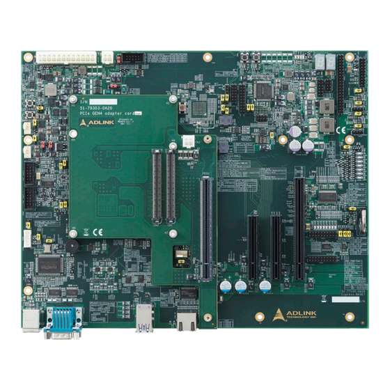
COM Express Type 7 Ryzen V3000 Dev Kit User’s Guide PICMG COM.0 R3.1 1.2. What’s Included 1.2.1 Standard Items Photo Part Number Description 85-77105-700E Express-BASE7 Plus The Type 7 reference carrier board supports PCIe Gen4 x16 and includes a 2... - Page 10 COM Express Type 7 Ryzen V3000 Dev Kit User’s Guide PICMG COM.0 R3.1 32-21019-0010-A0 THSF (Heatsink with Fan), exclusively for Express-VR7 Screws (2 pcs.) For securing the module and THSF. 95-17005-0000 PCIe x8 to two PCIe x4 adapter card (P8TO24) For function testing purposes.
- Page 11 COM Express Type 7 Ryzen V3000 Dev Kit User’s Guide PICMG COM.0 R3.1 7-pin SATA cable 30-10057-5010 180° (-) to 180° SATA power to Molex 4-pin cable 30-20171-1000 36-00621-0000 Plastic cylinder For lifting up the carrier board, 7 pcs Plastic screws for thecylinder 36-00622-0000 Quantity: 7 pcs.
-
Page 12: Optional Items
COM Express Type 7 Ryzen V3000 Dev Kit User’s Guide PICMG COM.0 R3.1 1.2.2 Optional Items Photo Part Number Description 85-79029-010E 10GbE SFP+ adapter card (CEI-2x10G-SFP+) Converts 2x 10GBASE-KR to 2x 10GbE SFP+ signals via Intel CS4224 PHY Dedicated for Express-VR7 module. -
Page 13: Getting Started
Insert the SO-DIMM memory into the COM Express-VR7 module’s SO-DIMM socket. Step 2 Remove all protective membranes from the thermal pads. Step 3 Secure the THSF onto the COM Express Type 7 module with the provided M2.5 screws. Page 13 Copyright © 2024 ADLINK Technology, Inc. - Page 14 COM Express Type 7 Ryzen V3000 Dev Kit User’s Guide PICMG COM.0 R3.1 Procedures Required Items Step 4 Place the assembled COM Express Type 7 module and THSF onto the connectors on the carrier board, as illustrated below. Page 14 Copyright © 2024 ADLINK Technology, Inc.
- Page 15 Procedures Required Items Step 5 Secure the COM Express Type 7 module to the carrier board from the solder side using the provided M2.5, L=16mm. Step 6 If you are installing a heatsink with fan, connect the fan’s plug into the carrier board, as shown below.
- Page 16 COM Express Type 7 Ryzen V3000 Dev Kit User’s Guide PICMG COM.0 R3.1 Step 7 If you need to use the SATA connectors on the back side of the carrier, install the provided cylinders to support the carrier board. Page 16...
-
Page 17: Gbe Adapter Cards
Note: To store the firmware for the 10GbE controller, an EEPROM dedicated is on the COM Express Type 7 module. This firmware can support selected SFP+ PHY and Copper PHY. Multiple firmware versions are stored on the 10GBE adapter card, as depicted in the structure below. -
Page 18: 10Gbe Base-T Card
COM Express Type 7 Ryzen V3000 Dev Kit User’s Guide PICMG COM.0 R3.1 3.1. 10GbE BASE-T Card CEI-2x10GBASE-T Exclusively for Express-VR7 usage, it converts 10GBASE-KR and related sideband signals into 10GBASE-T signals through Marvell AQR113C PHY. For more information, please download the user’s manual from ADLINK website. -
Page 19: 10Gbe Sfp+ Card
COM Express Type 7 Ryzen V3000 Dev Kit User’s Guide PICMG COM.0 R3.1 LAN LED Behavior LED Function LED Color LED State Description Speed Green/Yellow Lower than 1G Green Yellow Status & Activity Yellow No link Steady On Link established; no activity detected Blinking Link established;... - Page 20 COM Express Type 7 Ryzen V3000 Dev Kit User’s Guide PICMG COM.0 R3.1 SFP+ Transceiver Approved Vendor List (AVL): Brand Function Finisar FTLX8571D3BCL SFP+ Optical Netgear AXM761 SFP+ Optical Netgear AXM764 SFP+ Optical Intel FTLX1471D3BCVI31 SFP+ Optical Finisar FTLX8571D3BCL SFP+ Optical Page 20 Copyright ©...
-
Page 21: 10Gbe Adapter Card Installation
COM Express Type 7 Ryzen V3000 Dev Kit User’s Guide PICMG COM.0 R3.1 3.3. 10GbE Adapter Card Installation Below is an example of a 10GbE adapter card (using a 10GbE SFP+ card) being installed on the Express-BASE7 Plus carrier board with a Type 7 COM Express module. - Page 22 COM Express Type 7 Ryzen V3000 Dev Kit User’s Guide PICMG COM.0 R3.1 Note: The PCIe x16 slot, labeled with PCIEKR, features a proprietary pinout exclusively for 10GbE adapter cards. Page 22 Copyright © 2024 ADLINK Technology, Inc.
-
Page 23: Pcie X8 To Two Pcie X4 Adapter Card
COM Express Type 7 Ryzen V3000 Dev Kit User’s Guide PICMG COM.0 R3.1 4. PCIe x8 to two PCIe x4 Adapter Card A PCIe x8 or two PCIe x4 adapter cards allow you to use two PCIe x4 add-on cards in a single PCIe x8 slot, ideal for functionality testing. (For functionality test purpose.) -
Page 24: Debug Board
COM Express Type 7 Ryzen V3000 Dev Kit User’s Guide PICMG COM.0 R3.1 5. Debug Board DB40-HPC The DB40-HPC debug board provides COM Express system debugging functions with these features: Interface to SPI Flash for BIOS Update • Interface to EC for EC Update •... -
Page 25: Connecting The Com Express Module And Debug Card
COM Express Type 7 Ryzen V3000 Dev Kit User’s Guide PICMG COM.0 R3.1 5.1. Connecting the COM Express Module and Debug Card Three cables are required for firmware updates, as illustrated below: Page 25 Copyright © 2024 ADLINK Technology, Inc. -
Page 26: Buttons And Switches
COM Express Type 7 Ryzen V3000 Dev Kit User’s Guide PICMG COM.0 R3.1 5.2. Buttons and Switches This section describes the buttons and switches on the DB40 debug board. toggles the PWRBTN# signal for the COM Express moduleReset Button (RESET) -
Page 27: Display And Leds
COM Express Type 7 Ryzen V3000 Dev Kit User’s Guide PICMG COM.0 R3.1 5.3. Display and LEDs This section describes the hexadecimal display and LED functionality. 5.3.1 Boot-Up Procedure – Hexadecimal Display During power-up and BIOS execution, the CPU will first retrieve commands from POST and executes them. Each command is assigned a corresponding debug port data code or BIOS POST checkpoint code. -
Page 28: Embedded Controller (Ec) Status
COM Express Type 7 Ryzen V3000 Dev Kit User’s Guide PICMG COM.0 R3.1 Function EC_STATUS The LED will show the status of the EC on the COM-HPC module PWR_BTN# The LED will light up on an active power button signal of the COM-...
Need help?
Do you have a question about the COM Express Type 7 and is the answer not in the manual?
Questions and answers