
Related Manuals for ADLINK Technology DIN-1040


Summary of Contents for ADLINK Technology DIN-1040
- Page 1 DIN-1040 DIN Board User’s Manual Manual Rev.: Dec. 30, 2017 Revision Date: 50-11257-1000 Part No: Leading EDGE COMPUTING...
- Page 2 Leading EDGE COMPUTING Revision History Revision Release Date Description of Change(s) Dec. 30, 2017 Initial Release...
- Page 3 DIN-1040 Preface Copyright 2017 ADLINK Technology, Inc. This document contains proprietary information protected by copy- right. All rights are reserved. No part of this manual may be repro- duced by any mechanical, electronic, or other means in any form without prior written permission of the manufacturer.
- Page 4 Leading EDGE COMPUTING Conventions Take note of the following conventions used throughout this manual to make sure that users perform certain tasks and instructions properly. Additional information, aids, and tips that help users perform tasks. NOTE: NOTE: Information to prevent minor physical injury, component dam- age, data loss, and/or program corruption when trying to com- plete a task.
-
Page 5: Table Of Contents
DIN-1040 Table of Contents Preface ..................iii List of Tables................. vii List of Figures ................ ix 1 Introduction ................ 1 Overview................1 Specifications............... 1 I/O Connectors and Indicators ..........2 1.3.1 Digital I/O and Power..........3 1.3.2 RS-232 ............... 4 1.3.3... - Page 6 Leading EDGE COMPUTING This page intentionally left blank. Table of Contents...
-
Page 7: List Of Tables
Isolated Digital Input Pin Assignments ....... 7 Table 1-9: Isolated Digital Input Electrical Specification ....8 Table 1-10: Isolated Digital Output Pin Assignments ....8 Table 1-11: Isolated Digital Output Electrical Specification ... 9 Table 1-12: DIN-1040 Accessories..........12 List of Tables... - Page 8 Leading EDGE COMPUTING This page intentionally left blank. viii List of Tables...
-
Page 9: List Of Figures
Figure 1-2: Hardware Trigger Input Circuit ........6 Figure 1-3: Isolated Digital Input Circuit........7 Figure 1-4: Isolated Digital Output Circuit ........9 Figure 1-5: Connection Relay Application Circuit ......9 Figure 1-6: DIN-1040 Accessory Connection ......11 List of Figures... - Page 10 Leading EDGE COMPUTING This page intentionally left blank. List of Figures...
-
Page 11: Introduction
DIN-1040 Introduction 1.1 Overview The DIN-1040 is a terminal block that simplifies power and I/O sig- nal configuration for the ADLINK NEON-1020/40 smart camera. 1.2 Specifications I/O Interface 4 channel isolated multi-function open collector output Digital or exposure output function as... -
Page 12: I/O Connectors And Indicators
Leading EDGE COMPUTING I/O Interface D-SUB9 male connector, TXD and RXD signal RS-232 only 4 channel USB 1.1 full speed DC Output Isolation 5VDC, +/- 15%, max. 100mA DC Input 24V DC, +/- 10%, max. 30 VDC DC Input Power Over-current: (fuse 3A ) Protection Power reverse... -
Page 13: Digital I/O And Power
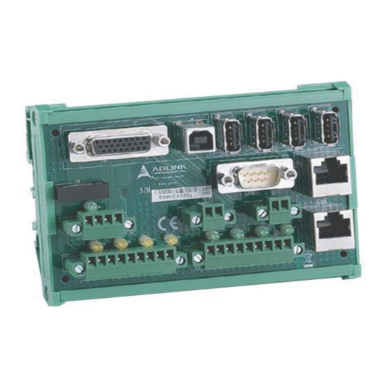
DIN-1040 Digital I/O and power Isolated Digital Output RS-232 Isolated Digital Input Power DI/O status LED PWM LED Output LAN Port USB Port (Type A) x4 Hardware Trigger Input USB Port (Type B) Table 1-1: I/O Connector Legend 1.3.1 Digital I/O and Power... -
Page 14: Table 1-2: Digital I/O And Power Pin Assignments
Leading EDGE COMPUTING Signal Signal System PWR DO0 /Strobe out 0 System PWR Table 1-2: Digital I/O and Power Pin Assignments 1.3.2 RS-232 A D-SUB9 (male) connector Signal Table 1-3: System UART Pin Assignments Introduction... -
Page 15: Main Power
DIN-1040 1.3.3 Main Power Signal Power in (+) Isolated 5V power out Isolated GND Table 1-4: Power Pin Assignments 1.3.4 PWM LED Control Out Signal PWN output (+) PWN output (-) Table 1-5: PWM LED Pin Assignments Introduction... -
Page 16: Hardware Trigger Input
Hardware Trigger Input One hardware trigger input is provided. Hardware Trigger input (+) 1.2kΩ 1kΩ Hardware Trigger input (-) Max. 24VDC DIN-1040 NEON-1020/1040 Figure 1-2: Hardware Trigger Input Circuit Min. Max. Number of Channels 1 digital input Normal Input High Threshold... -
Page 17: Table 1-8: Isolated Digital Input Pin Assignments
DIN-1040 Signal DI0 (+) DI0 (-) DI1 (+) DI1 (-) DI2 (+) DI2 (-) DI3 (+) DI3 (-) Isolated GND Table 1-8: Isolated Digital Input Pin Assignments DI(+) 2.4k DI(-) DIN-1040 Figure 1-3: Isolated Digital Input Circuit Min. Max. Number of Channels... -
Page 18: General Purpose Isolated Digital Output
Leading EDGE COMPUTING Min. Max. Max. Input Voltage +24V Table 1-9: Isolated Digital Input Electrical Specification 1.3.8 General Purpose Isolated Digital Output Four isolated digital output channels are provided, such that, in the common ground connection of digital output, as shown, when a 1 (logic high) is written by FPGA to a DO channel, sink current passes through the transistors and the DO channel goes low, and when a 0 (logic low) is written by FPGA to a DO channel, no cur-... -
Page 19: Table 1-11: Isolated Digital Output Electrical Specification
DIN-1040 ISO +5V Flyback diode DO (+) Isolated GND DIN-1040 Figure 1-4: Isolated Digital Output Circuit Relay coil supply (+) ISO +5V Flyback diode DO (+) Relay Isolated GND Relay coil supply (-) DIN-1040 Figure 1-5: Connection Relay Application Circuit... -
Page 20: Led Status Indicators
Leading EDGE COMPUTING 1.3.9 LED Status Indicators Color Status Indicator DC power on: ON Green DC power off: OFF DI high: ON Green DI low: OFF DI high: ON Green DI low: OFF DI high: ON Green DI low: OFF DI high: ON Green DI low: OFF... -
Page 21: Accessory Connection
DIN-1040 1.4 Accessory Connection Figure 1-6: DIN-1040 Accessory Connection Introduction... -
Page 22: Table 1-12: Din-1040 Accessories
Leading EDGE COMPUTING Accessory 30-01203-0010 VGA & USB cable 30-01246-0000 Gig E cable 30-01201-0000 Power & DI/O cable Table 1-12: DIN-1040 Accessories Introduction... -
Page 23: Important Safety Instructions
DIN-1040 Important Safety Instructions For user safety, please read and follow all instructions, Warnings, Cautions, and Notes marked in this manual and on the associated device before handling/operating the device, to avoid injury or damage. S'il vous plaît prêter attention stricte à tous les avertissements et mises en garde figurant sur l'appareil , pour éviter des blessures... - Page 24 Leading EDGE COMPUTING Never attempt to repair the device, which should only be serviced by qualified technical personnel using suitable tools A Lithium-type battery may be provided for uninterrupted backup or emergency power. Risk of explosion if battery is replaced with one of an incorrect type;...
- Page 25 DIN-1040 BURN HAZARD Touching this surface could result in bodily injury. To reduce risk, allow the surface to cool before touching. RISQUE DE BRÛLURES Ne touchez pas cette surface, cela pourrait entraîner des blessures. Pour éviter tout danger, laissez la surface refroidir avant de la toucher.
- Page 26 Leading EDGE COMPUTING This page intentionally left blank. Important Safety Instructions...
-
Page 27: Getting Service
San Jose, CA 95138, USA Tel: +1-408-360-0200 Toll Free: +1-800-966-5200 (USA only) Fax: +1-408-360-0222 Email: info@adlinktech.com ADLINK Technology (China) Co., Ltd. 300 Fang Chun Rd., Zhangjiang Hi-Tech Park Pudong New Area, Shanghai, 201203 China Tel: +86-21-5132-8988 Fax: +86-21-5132-3588 Email: market@adlinktech.com...
Need help?
Do you have a question about the DIN-1040 and is the answer not in the manual?
Questions and answers